


Aspects importants de la conception du haut fourneau et des équipements auxiliaires associés
Aspects importants de la conception du haut fourneau et des équipements auxiliaires associés
La conception du haut fourneau (BF) proprement dit et de ses équipements associés et auxiliaires (Fig 1) immédiatement en amont et en aval du four est importante pour le fonctionnement efficace du BF. Outre le four proprement dit, les équipements associés immédiats comprennent (i) le magasin de stockage, (ii) l'équipement de chargement, (iii) le haut du four, (iv) le système de refroidissement et (v) l'équipement de la zone de l'atelier de coulée.
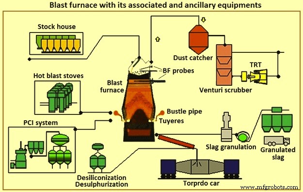
Fig 1 Haut fourneau avec ses équipements associés et auxiliaires
La fabrication du fer BF consiste en un système composé de plusieurs composants qui fonctionnent en harmonie. Une application et un fonctionnement corrects de ces composants sont nécessaires pour soutenir le processus de fabrication du fer. La sélection de composants spécifiques dépend de facteurs tels que les conditions existantes, les contraintes physiques, les exigences de production, le coût, le calendrier, la fiabilité et la maintenabilité. L'interdépendance des composants est aussi importante pour le bon fonctionnement du système que leur capacité individuelle. Il existe des exigences majeures et des pratiques « normales » pour chaque domaine ou composant. Il existe également des technologies alternatives disponibles dans le commerce qui présentent des avantages et des inconvénients inhérents.
BF convertit la charge de minerai de fer en fer liquide (métal chaud). Au BF sont associées des batteries de fours à coke qui convertissent le charbon en coke, et des usines d'agglomération et de bouletage, qui préparent le minerai de fer pour le BF. Le BF convertit ces matières premières préparées en un produit de plus grande valeur. Le métal chaud de certaines des opérations des BF est utilisé dans les fonderies pour la production de pièces moulées en fonte. D'autres opérations produisent un métal chaud à faible teneur en silicium qui est transformé en acier dans un atelier de fusion d'acier. Une partie de la fonte est convertie en fonte brute dans les machines de coulée rugueuse. Les sous-produits du BF sont les scories, le gaz de gueulard du BF, la poussière de carneau et le gâteau de filtration. Ces sous-produits peuvent avoir un impact économique positif ou négatif, selon les possibilités locales d'utilisation.
Certains des nombreux aspects affectant chaque considération pour la conception ou la re-conception de BF sont (i) le profit, (ii) la santé et la sécurité des employés, (iii) la protection de l'environnement, (iv) les réglementations statutaires, (v) les besoins du marché et de la transformation en aval, (vi) les ressources humaines, de construction et de maintenance disponibles, (vii) l'évolution des technologies et l'obsolescence des équipements, (viii) les matières premières, les services publics et autres matériaux disponibles, et (ix) ainsi de suite. Toute contrainte sérieuse dans l'un de ces aspects peut mettre en péril la viabilité de l'unité BF (ou même d'une aciérie) ou empêcher ou nécessiter la construction d'une nouvelle BF.
Les BF sont normalement regroupés par taille. Les mini BF produisent moins de 1 500 tonnes de métal chaud par jour (tML/jour), les petits BF produisent dans la plage d'environ 2 500 tML/jour à 5 000 tML/jour, les moyens BF produisent dans la plage d'environ 6 000 tML/jour à 8 000 tML/jour, et les grands BF produisent environ 9 000 tML/jour à 12 000 tML par jour. Dans une aciérie intégrée, un nombre et des tailles de BF sont nécessaires pour fournir le métal chaud nécessaire à la production d'acier. Les aciéries intégrées avec un certain nombre de BF sont moins affectées lorsqu'un BF subit des réparations de regarnissage ou lorsqu'il y a des problèmes de contrôle du four. Les petits BF ont des réparations de regarnissage plus courtes que les grands BF et sont considérés comme plus faciles à utiliser. Cependant, le coût du métal chaud des petits BF est plus élevé. L'aciérie intégrée doit exploiter le nombre minimum de fours rentables. Dans certains cas, des mises à niveau sont effectuées afin de réduire le nombre de fours en fonctionnement.
Les BF sont regarnis périodiquement après la fin de sa campagne (temps entre les réparations de regarnissage). Dans le passé, cela impliquait le remplacement du revêtement intérieur en brique du four principal. Ces derniers temps, la reconstruction, le remplacement et la maintenance préventive de composants étendus sont effectués en même temps. Avec cette pratique, l'aciérie la plus efficace avec moins de grands BF perd un pourcentage plus élevé de sa production pendant la réparation du regarnissage BF que l'usine avec plus de petits fours. Afin d'avoir à la fois le faible coût d'exploitation et le minimum d'interférences lors des regarnissages BF, l'industrie s'est efforcée de maximiser la campagne des BF et de réduire la durée de la réparation de regarnissage. La tendance claire actuelle dans les aciéries intégrées est d'exploiter moins de grands fours et d'utiliser des techniques et des conceptions qui prolongent indéfiniment la campagne BF.
Dans le même temps, la réduction de la variabilité des produits est devenue plus importante et, par conséquent, des investissements sont réalisés dans l'automatisation qui améliorent le suivi et le contrôle du processus. Les opérateurs BF, le personnel de maintenance, les concepteurs et le personnel de recherche ont appliqué une technologie moderne et des méthodes analytiques au processus BF afin de mieux surveiller et contrôler le processus. En conséquence, l'écart type de la qualité du métal chaud a été réduit. Des systèmes de collecte de données améliorés fournissent également davantage d'informations aux fournisseurs et aux fabricants. Cela a amélioré la sélection des matériaux et la conception des BF et des équipements associés. La durée des campagnes a augmenté à environ 20 ans auparavant, passant de 5 ans à 10 ans.
La fabrication du fer BF est une technologie vieille de plus de 430 ans. Même ainsi, l'utilisation de fonte BF reste la méthode la plus couramment utilisée dans les aciéries intégrées pour la production d'acier. Les processus actuels d'usines sidérurgiques intégrées reposent sur le BF pour fournir dans les délais des quantités prévisibles de métal chaud de qualité constante. La variation de l'un des aspects de l'approvisionnement en métal chaud a un impact sérieux sur le reste des processus de production d'acier. Par conséquent, le BF continue d'être un processus clé dans les aciéries intégrées modernes.
Parfois, il est dit que la technologie de procédé BF est en fin de vie utile. Ce n'est pas le cas. L'étude des données d'exploitation de 23 ans (1970 à 1993) d'un couple typique de BF de taille moyenne a montré qu'il y a une augmentation moyenne de la productivité de 3 % par an (Fig 2a). Dans le même temps, la réduction moyenne du taux de carburant a été de 1 % par an (Fig 2b). En outre, le temps productif entre le regarnissage BF (la campagne) a été prolongé grâce à des améliorations de l'équipement, des matériaux et de la conception. En conséquence, le coût global de production de la fonte, corrigé de l'inflation, s'est amélioré encore plus que ne l'indiquent les données d'exploitation. Par conséquent, la technologie de procédé BF n'est pas morte bien qu'il s'agisse d'une technologie vieille de plus de 430 ans. Il progresse encore dans tous les domaines à un rythme considérable. Le BF reste aujourd'hui une science dynamique soutenue par des technologies en constante amélioration.
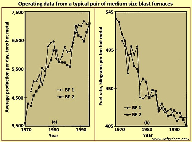
Fig 2 Données de fonctionnement d'une paire typique de hauts fourneaux de taille moyenne
Mise en page du BF
L'agencement d'un BF est essentiellement un exercice d'intégration de l'équipement nécessaire pour manipuler les différents matériaux nécessaires à la fabrication du métal chaud et des produits et sous-produits qui en résultent. La conception la plus efficace s'adapte correctement à l'ensemble du processus et son efficacité est jugée du point de vue à la fois de l'investissement initial en capital et des coûts d'exploitation permanents. L'aménagement de l'atelier BF dépend de plusieurs facteurs tels que (i) le terrain du site, (ii) les conditions climatiques, (iii) la méthode de livraison des matières premières, (iv) les systèmes et emplacements de traitement des matières premières dans l'usine, (v) les systèmes de traitement en aval et emplacements, (vi) les exigences de quantité/débit pour la fonte, (vii) le type et la taille de la flotte de livraison de fonte, et (viii) ainsi de suite. La figure 3 montre une disposition simplifiée d'une usine BF.
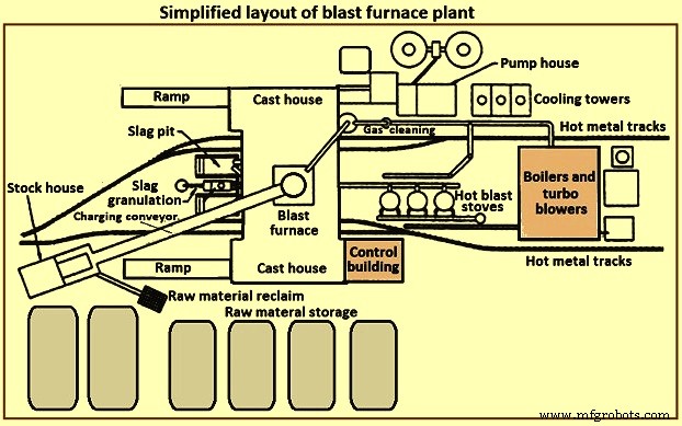
Fig 3 Plan simplifié d'une installation de haut fourneau
Une installation BF se compose généralement de plusieurs sections. Ces sections sont (i) le stockage, la manutention et la récupération des matières premières, (ii) le magasin de stockage, (iii) le système de chargement, (iv) le four proprement dit, (v) la salle de coulée, (vi) le traitement et la manutention des scories, (vii) manutention du métal chaud, (viii) poêles à vent chaud et système de vent chaud, (ix) installation d'épuration des gaz, (x) services publics, (xi) système d'automatisation et de contrôle, (xii) installations de maintenance et (xiii) installations de soutien du personnel.
Stockage et manutention des matières premières
Les matières premières telles que le minerai de fer, l'aggloméré, les boulettes, les fondants, le charbon, le coke, etc. proviennent soit de sources externes, soit sont produites dans l'aciérie intégrée. Ces matières premières nécessitent un stockage contrôlé suffisant pour soutenir les opérations BF. La capacité de stockage est nécessaire en cas d'interruptions de livraison prévisibles ou d'interruptions imprévisibles. Une capacité de stockage supplémentaire peut être nécessaire en cas d'éventuels changements dans la provenance de certaines matières premières. Des emplacements de stockage séparés sont nécessaires en raison des caractéristiques physiques ou chimiques différentes de matériaux similaires. Le mélange de matériaux similaires peut entraîner des problèmes de contrôle de processus / métallurgiques. Les piles de stockage doivent être séparées pour empêcher le mélange de matériaux différents. Les pieux doivent être placés sur des lits préparés pour permettre aux opérateurs de l'équipement de récupération des matières premières de faire la distinction entre le matériau principal et le matériau étranger. Les tas sont disposés de manière à minimiser la dégradation des matériaux et à empêcher le ramassage des fines par le vent. Des vaporisateurs d'eau et des agents de cocooning peuvent être utilisés pour minimiser le ramassage / l'entraînement de la poussière par les vents.
Plusieurs techniques différentes sont disponibles pour la mise en place et la récupération des matières premières. Les techniques de dépôt comprennent le basculement des wagons, les ponts à minerai, les convoyeurs d'empilage, les racleurs, etc. les systèmes doivent être dimensionnés pour assurer le débit nécessaire à l'usine BF.
Stock house
Le magasin de stockage est l'unité de stockage de l'opérateur BF pour l'alimentation directe de la charge dans le four. Des bacs de stockage sont fournis pour chacun des matériaux de charge pour le BF. Des bacs individuels sont fournis pour des matériaux similaires (c'est-à-dire frittés, granulés) ayant des propriétés métallurgiques différentes. Le magasin de stockage offre une capacité adéquate pour les divers matériaux de charge en cas de rupture à court terme de l'approvisionnement des zones de stockage des matières premières. Les capacités typiques de débit des bacs de stockage, en cas de perte d'alimentation en matières premières, sont (i) coke - 2 heures à 8 heures, (ii) matériaux contenant du fer (minerai, aggloméré et boulettes) - 4 heures à 16 heures, et flux et autres matériaux divers – 8 heures à 24 heures. Ces capacités sont basées sur la production nominale du four et varient en fonction de la fiabilité et du temps d'accès pour leur remplacement à partir des stocks ou d'un fournisseur.
Les matériaux de charge ont tendance à se dégrader en raison des conditions climatiques et des manipulations répétées. Plus le nombre de fois que le matériau est manipulé est élevé (stockage, récupération, déversement, goulottes de convoyeur, godets de pont de minerai, etc.), plus le pourcentage de fines dans le fardeau est élevé. Le procédé BF nécessite une perméabilité contrôlée et donc une charge contrôlée. Le chargement de fines excessives, soit normalement tout au long de la charge, soit concentré sur de courtes périodes de chargement spécifiques, peut perturber le procédé BF et endommager l'équipement du four. L'entrepôt offre la dernière possibilité raisonnable d'éliminer les fines avant de les charger dans le four. Dans la mesure du possible, des cribles vibrants sont installés après les bacs de stockage du coke, du minerai, de l'aggloméré et des pellets pour éliminer la majeure partie des fines. Les fines retirées sont collectées pour être recyclées. Certains opérateurs BF facturent des amendes à des zones spécifiques du four pour ajuster la perméabilité locale du four et contrôler les charges thermiques sur les parois du four.
Des jauges d'humidité sont fréquemment fournies dans l'entrepôt pour surveiller les quantités d'eau réelles chargées dans la fournaise. Ces informations permettent d'ajuster les quantités de charge pour compenser les conditions ambiantes variables (c'est-à-dire une humidité de coke plus élevée pendant la période des pluies).
Étant donné que différents types et quantités variables de matériau de charge sont nécessaires pour soutenir le fonctionnement continu du BF, les matériaux de charge doivent être fournis dans une séquence spécifique (qui elle-même peut être modifiée fréquemment pour prendre en charge les paramètres de fonctionnement variables du four). Par conséquent, l'entrepôt doit être équipé d'un équipement fiable pour extraire et alimenter des quantités précises de matériaux de charge spécifiques pour respecter un calendrier spécifique. La figure 4 montre une disposition simplifiée de l'équipement dans l'entrepôt.
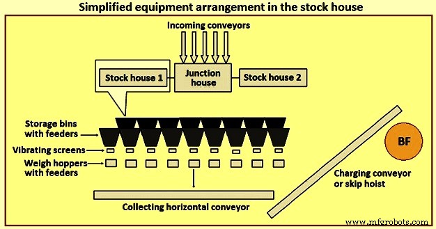
Fig 4 Disposition simplifiée de l'équipement dans l'entrepôt
Auparavant, le type de stock house le plus courant était le type highline. Ce type d'entrepôt est situé directement à côté de la fournaise. Des wagons ou des ponts roulants alimentent le bac de stockage tandis que les bacs de stockage alimentent directement un wagon à bascule mobile. Un opérateur de wagon-bascule contrôle manuellement la porte de déchargement du bac pour alimenter des quantités spécifiques de matériau dans la trémie équipée d'une balance située dans le wagon-bascule. Après avoir collecté les types et les quantités de matériaux appropriés, l'opérateur déplace la voiture de pesée à une position au-dessus de la « fosse à benne » et décharge la charge, à travers une goulotte, dans une voiture à benne en attente. Le wagonnet est ensuite hissé jusqu'au sommet du four.
Le type d'entrepôt de type highline, en conjonction avec une voiture à échelle, a présenté peu d'options pour la fourniture de criblage de charges ferreuses (minerai, aggloméré et boulettes). Au fur et à mesure que la connaissance du processus BF a augmenté, des exigences plus strictes pour la charge se sont développées. Le concept de « fardeau technique » est bien reconnu aujourd'hui dans l'industrie. Il est normalement admis qu'il y a des limites à la flexibilité et à l'adaptabilité de l'entrepôt highline pour répondre à cette exigence. Par conséquent, le type highline de la cour de stockage a été remplacé par le magasin de stockage automatisé à convoyeur pour fournir les matériaux de charge au BF.
L'entrepôt automatisé est normalement de deux types distincts et différents. Le premier type est le remplacement de la balance sous les bacs de matières premières par un système d'alimentation et de bande transporteuse. Des convoyeurs séparés sont fournis pour chaque type de matières premières (coke, matériaux contenant du fer, et matériaux de fondant et additifs, etc.) sur lesquels des rangées de bacs de stockage sont montées, avec des alimentateurs vibrants pour décharger les matériaux de charge des bacs de stockage vers les convoyeurs. Pour les matériaux contenant du coke et du fer, un crible vibrant est situé à la décharge de chaque convoyeur pour cribler le matériau et alimenter le matériau criblé dans les trémies de pesage. Ce type de système continue d'alimenter les trémies de pesée avant les bennes.
Le deuxième type d'entrepôt automatisé est une grande structure de bacs de stockage construite entièrement au-dessus du sol et assez éloignée du BF. Cela se fait normalement pour les BF où un convoyeur à bande est utilisé pour transporter les matériaux de charge vers le haut du four au lieu des wagons à benne. La méthode de remplissage des bacs de stockage se fait normalement par un système de bande transporteuse. Les matières premières sont extraites des bacs de stockage par des alimentateurs vibrants et des convoyeurs à bande dans des trémies de pesage. Les trémies de pesée déchargent à leur tour le matériau sur le convoyeur principal au moyen d'un convoyeur de collecte. Les trémies de pesage sont programmées pour peser les matières premières dans le bon ordre sur le tapis roulant principal jusqu'au sommet du four.
La fourniture d'un magasin de stockage automatisé peut fournir une alimentation plus efficace en matière première au magasin de stockage et une sélection, un criblage, un pesage et une livraison plus efficaces de la charge au four. Le magasin de stockage automatisé peut être situé directement à côté du chariot d'alimentation du four, ou peut être situé à distance du four pour le chargement via un tapis roulant.
L'automatisation de l'entrepôt a considérablement augmenté la capacité de production, amélioré l'efficacité opérationnelle et éliminé les écarts d'exploitation causés par les opérateurs et l'équipement. Cependant, dans la pratique, un entrepôt moderne et automatisé peut être assez complexe. L'entrepôt lui-même peut être alimenté par des convoyeurs, qui à leur tour déchargent sur des convoyeurs à bascule pour distribuer les matériaux aux différents bacs. La disposition des convoyeurs et de l'équipement dans l'entrepôt peut être organisée de nombreuses façons. Le placement de l'entrepôt à côté du four entraîne souvent une congestion de l'agencement et limite la flexibilité pour les modifications futures.
Système de levage
Les matériaux de charge sont normalement hissés au sommet BF à l'aide de wagons à benne ou par bande transporteuse.
Ignorer le levage de voiture - L'utilisation de la benne pour BF a évolué à partir de l'industrie minière. Les bennes BF sont dimensionnées en fonction du débit du four. De toute évidence, plusieurs facteurs tels que la capacité de levage, la conception du pont de benne, etc., ont leurs propres influences ou contraintes sur la taille de la benne.
Normalement, deux bennes fonctionnent de manière opposée (pour réduire la puissance de levage nécessaire) sur un palan commun. Les bennes se déplacent sur des rails sur un pont à benne, normalement installé à une inclinaison d'environ 60 degrés à 80 degrés par rapport à l'horizontale. La benne complète accélère lentement lorsqu'elle quitte la fosse de la benne, accélère aussi rapidement que possible pour atteindre et se déplacer à la vitesse maximale pendant la majeure partie de l'ascenseur. Le treuil ralentit la benne lorsqu'elle s'approche du sommet du pont de la benne. Les roues de la benne sont guidées par les rails de déversement et de corne lorsque la benne est renversée dans l'équipement de chargement supérieur du four. Alors que la benne de levage atteint et s'arrête à la position de déversement finale, la benne vide (descendant aux mêmes vitesses) atteint juste le bas de sa course dans la fosse de la benne, en attente de remplissage. Le système de chargement par benne est une technique fiable et efficace pour acheminer la charge vers le haut du four. Cependant, il manque de flexibilité pour l'opérateur dans la mesure où les bennes ne peuvent contenir qu'une quantité spécifique de matériau (une surcharge entraîne un surremplissage ou des charges de levage excessives) ou devient inefficace si de petits volumes de charge spécifique sont nécessaires. La figure 5 montre le schéma du levage de la benne.
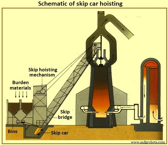
Fig 5 Schéma du levage de la benne
Convoyeur de chargement du four – Avec le convoyage de l'entrepôt est venu le convoyage du système de levage. Il est maintenant courant que les entrepôts soient situés à distance du four et une grande bande transporteuse transporte la charge jusqu'au sommet du four. Si le haut du four a une hauteur d'environ 60 mètres, puis un tapis roulant installé à une inclinaison de 8 degrés par rapport à la position horizontale, l'entrepôt doit être situé à au moins 427 mètres du four. Les inclinaisons plus prononcées de la bande sont normalement évitées pour minimiser le recul du matériau. Il est normal de charger des matériaux divers directement au-dessus et après la fin d'une charge ferreuse sur la bande transporteuse afin de maintenir les matériaux ferreux en place jusqu'à ce qu'ils atteignent le haut du four.
Système de charge en haut du four
Le four proprement dit fonctionne avec une haute pression positive. Le gaz BF composé partiellement de monoxyde de carbone, de dioxyde de carbone et d'azote est généré par le procédé BF avec de grandes quantités de poussière entraînée. L'opérateur BF doit maintenir la pression maximale en raison des avantages du procédé et contenir les gaz et la poussière (à la fois pour la valeur du combustible et à des fins de contrôle environnemental). Cependant, l'opérateur doit régulièrement placer des matériaux de charge à l'intérieur du haut du four afin de réapprovisionner le processus interne, sans perdre la pression du haut du four.
Haut de type cloche – Depuis plusieurs années, le type de voûte de four le plus courant est le voûte à deux cloches (Fig 6). Au fur et à mesure que la charge atteint le haut du four (par benne ou par convoyeur), elle tombe dans une trémie de réception et dans la petite trémie cloche. La petite cloche (coule d'acier de forme conique d'environ 2,6 mètres de diamètre et de 1,4 mètre de haut pour un BF de 5 000 tML par jour) s'abaisse et permet à la charge de tomber dans la grande trémie cloche. La petite cloche est soulevée et se scelle contre un siège fixe sur la trémie de la petite cloche. En fonction du volume de la grande trémie à cloche, des charges supplémentaires de charge sont séquencées dans la grande trémie à cloche par la petite cloche. Tout au long de ce processus, la grande cloche est restée fermée, scellant le four. Lorsque les bons nombres de charge de la charge ont été collectés, la grande cloche (moulage d'acier de forme conique d'environ 5,5 mètres de diamètre et d'environ 3,5 mètres de haut pour un BF de 5 000 tML par jour) s'abaisse et permet à la charge de glisser le long de la cloche dans le haut du four proprement dit. Une fois la charge déchargée, la grande cloche est soulevée et se scelle contre le dessous de la grande trémie à cloche. La figure 6 montre les systèmes de charge supérieurs de type cloche BF.
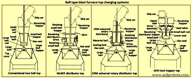
Fig 6 Systèmes de chargement par le haut de haut-fourneau de type Bell
De toute évidence, le contrôle de la répartition de la charge avec le four pour ce type de dessus est limité par la façon dont la charge est placée uniformément sur la grande cloche (le saut de déversement entraîne un placement inégal de la charge dans ce type de dessus) et les courbes descendantes du des matériaux de charge spécifiques (c'est-à-dire du coke ou de la charge de fer) lorsqu'ils glissent et tombent de la grande cloche. En outre, le dessus à deux cloches est susceptible de perdre l'étanchéité des grandes et petites cloches et de la garniture entre la grande tige de cloche et le petit tube de cloche. Les fuites de la cloche résultent de l'abrasion par le matériau de charge glissant sur les surfaces d'étanchéité de la cloche. La fuite de la garniture de la tige est le résultat de l'abrasion des fines provenant soit de l'intérieur du four, soit de la collecte sur la grande tige de la cloche après que la charge a été déversée dans la trémie de réception.
Afin de minimiser l'usure de la grande surface d'étanchéité de la cloche, du gaz BF prélevé à l'intérieur du four est introduit entre les cloches pour égaliser l'espace (réduisant le différentiel de pression sur la grande surface d'étanchéité de la cloche). Ce gaz est libéré dans l'atmosphère avant l'ouverture de la petite cloche pour permettre l'introduction de plus de charge. Certaines des options disponibles pour améliorer les limitations du système de toit à deux cloches sont indiquées ci-dessous.
Le distributeur McKEE - Le distributeur McKEE (Fig 6) a été pendant plusieurs années la principale amélioration de la répartition de la charge disponible pour le toit de type à deux cloches. Cependant, il est rapidement remplacé par d'autres technologies. Sa conception intègre la possibilité de faire pivoter ensemble la petite cloche et la petite trémie pendant que le chariot benne se décharge. La charge est répartie uniformément dans la petite trémie à cloche, améliorant ainsi le placement uniforme de la charge sur la grande cloche. Ce type de dessus est sujet à une petite et grande usure de la cloche et à une perte d'étanchéité qui en résulte.
Haut distributeur rotatif universel CRM – Le distributeur rotatif universel CRM (Centre Recherches Métallurgiques – Belgique) (Fig 6) a été développé pour éliminer la perte de l'effet d'étanchéité en cloche. Deux cloches (une cloche de scellement et une cloche de matière) sont installées à la place de la petite cloche normale. Une trémie de chargement rotative est montée sur la cloche de matériau. La cloche d'étanchéité est située sous la cloche de matériau et scelle contre un siège fixe. Pendant la décharge de la benne, la trémie de charge et la cloche de matériau fermée sont tournées pour remplir uniformément la trémie. Lorsque le remplissage est terminé, la rotation de la trémie s'arrête. Lorsqu'il est temps de vider sur la grande cloche, la trémie rotative, la cloche de matériau et la cloche de scellement sont abaissées. La cloche d'étanchéité descend sous le siège fixe. À mi-chemin du processus d'abaissement, la descente de la trémie est arrêtée et la cloche de matériau et la cloche de scellage continuent de descendre jusqu'à ce qu'elles atteignent leur position d'arrêt. Au fur et à mesure que l'espace s'ouvre entre la cloche de matériau et la trémie, la charge se décharge uniformément dans la grande trémie à cloche. Lorsque la charge quitte l'espace, elle n'entre pas en contact avec la surface de siège de la soupape d'étanchéité, maintenant ainsi la capacité d'étanchéité supérieure. Ce style de dessus est capable de maintenir une pression interne de 0,2 MPa.
Le dessus CRM améliore la capacité d'étanchéité et la longévité du dessus à deux cloches. Il ne fournit cependant pas une amélioration spectaculaire de la répartition de la charge du four par rapport au distributeur McKEE et n'élimine pas la vulnérabilité de la grande surface d'étanchéité de la cloche.
Le dessus de la trémie de verrouillage GHH – Le dessus de la trémie de verrouillage GHH (Fig 6) est la modification du dessus à deux cloches. Il réduit la dépendance à l'égard de la grande cloche pour maintenir une étanchéité au gaz. L'ajout de trémies de verrouillage avec des vannes d'étanchéité séparées pour chaque emplacement de vidage de benne offre une capacité supplémentaire pour sceller le dessus. La grande cloche peut fonctionner sans pression différentielle sur sa surface d'étanchéité (c'est-à-dire que la pression supérieure du four est égale à la pression de la trémie de la grande cloche). L'opération est donnée ci-dessous.
Une benne déverse la charge de charge dans la trémie de verrouillage à travers une trémie de réception et une vanne à joint ouvert. La charge est placée sur la clochette rotative et remplit uniformément la trémie de distribution rotative au-dessus de la clochette. Un joint entre la trémie de verrouillage et la trémie à petite cloche rotative est ouvert pendant que la rotation est en cours. Lorsque la décharge de charge de la benne est terminée, la vanne d'étanchéité et le joint entre la trémie de verrouillage et la petite trémie de cloche sont fermés. Le gaz d'égalisation est introduit et la trémie de verrouillage est pressurisée à la pression supérieure du four. La petite cloche est ensuite abaissée pour introduire la charge dans la grande trémie à cloche. La petite cloche se ferme et la pression de la trémie de verrouillage est soulagée dans l'atmosphère. La vanne d'étanchéité du côté opposé (c'est-à-dire à l'autre position de vidage de la benne) est ouverte. Le joint entre la trémie de la serrure et la trémie de la petite cloche s'ouvre. La rotation de la petite cloche et de la trémie commence. Le haut est maintenant capable d'accepter le fardeau de l'autre capitaine.
Ce type de dessus améliore l'étanchéité et la longévité du dessus à deux cloches. Le dessus de la trémie verrouillable, cependant, ne fournit pas une amélioration spectaculaire de la répartition de la charge du four par rapport au dessus McKEE ou CRM. Bien que la grande cloche ne soit plus nécessaire pour effectuer une fonction d'étanchéité, la longévité de l'effet d'étanchéité de la petite cloche est toujours critique.
Armure mobile – L'étape majeure franchie pour améliorer la répartition de la charge du toit de type cloche a été la mise au point d'un blindage mobile (Fig 7). Des déflecteurs réglables sont installés dans la zone de la gorge du four pour dévier la charge après qu'elle ait glissé de la grande cloche. L'armure mobile est ajustée en fonction du matériau de charge spécifique déchargé et de l'endroit où l'opérateur souhaite placer la charge dans le four.
Plusieurs fabricants proposent différents types d'armures mobiles. Les segments d'armure individuels peuvent être déplacés uniformément (simultanément et de manière égale) à l'intérieur du four pour placer la charge dans un motif annulaire. D'autres types d'armures mobiles sont disponibles pour fournir un contrôle individuel des plaques d'armure afin d'obtenir un modèle de distribution non circulaire.
Certains inconvénients associés à l'armure mobile sont (i) la majorité des composants mécaniques et d'usure se trouvent dans l'environnement difficile du cône supérieur du four, (ii) une certaine perte de volume de travail interne est nécessaire pour fournir un dégagement entre l'armure mobile et la ligne de stock de conception (bien que cette zone du four ne puisse pas être classée comme une zone de productivité approximative pour la prise en compte du volume de travail du four, et (iii) une capacité limitée à dévier la charge vers le centre même du four, en particulier lorsque le niveau de la ligne de stock est déjà élevé. caractéristique des plombs annule souvent le déplacement limité du blindage mobile.
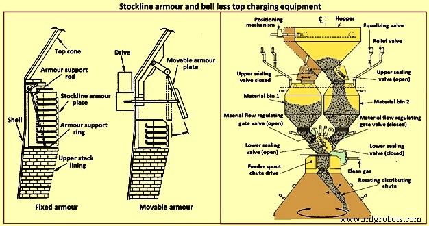
Fig 7 Armure Stockline et équipement de chargement supérieur sans cloche
Système de charge supérieur sans cloche – Au début des années 1970, la société luxembourgeoise Paul Wurth S.A. a mis au point le système de recharge sans cloche (BLT) (Fig. 7). Ce type de dessus de four est une rupture radicale avec le dessus de type cloche. La charge peut être placée dans le four selon n'importe quel modèle requis par l'opérateur du four. Les anneaux annulaires, les spirales, les segments et le placement des points sont des modèles courants réalisables par inclinaison et rotation synchronisées ou indépendantes d'une goulotte de distribution de charge située avec le cône supérieur du four.
L'étanchéité du haut du four est maintenue tout au long de la campagne du four. Les activités de maintenance sont simples et de courte durée. Normalement, le BLT se compose d'une goulotte ou d'une trémie de réception (recevant la charge des bennes ou d'un tapis roulant), d'une trémie à écluse avec vannes d'étanchéité supérieure et inférieure, d'une porte de contrôle du flux de matière, d'une boîte de vitesses d'entraînement de la goulotte principale (un système à eau ou à gaz -unité refroidie utilisée pour la rotation et l'inclinaison de la goulotte) et la goulotte de distribution de la charge. Il existe trois principaux types de BLT, à savoir (i) la trémie parallèle, (ii) l'alimentation centrale et (iii) le type compact.
En règle générale, le type parallèle comprend deux trémies verrouillables (les trémies ont été installées sur certains fours à des fins de débit et de secours ; un type de trémie "excentrique" a été installé pour une application avec dégagement restreint). Depuis le début des années 1980, plusieurs BF ont sélectionné le type de trémie à verrouillage unique à « alimentation centrale » pour ses améliorations dans la ségrégation de la charge et le contrôle de la répartition de la charge, ce qui améliore le fonctionnement du four.
Un type « compact » de dessus BLT a été développé pour les fours de petite et moyenne taille afin de permettre l'introduction du BLT (et de ses avantages) dans les fours où les autres types de BLT plus grands ne peuvent pas être utilisés en raison de contraintes de coût ou physiques. Les étapes du fonctionnement du BLT pour un type d'alimentation central sont (i) la charge est déchargée d'une benne ou d'un tapis roulant à travers une goulotte ou une trémie de réception au-delà d'une vanne à joint ouvert dans la trémie de verrouillage, (ii) après que la charge est reçue dans la serrure trémie, la vanne d'étanchéité supérieure est fermée et du gaz d'égalisation est introduit pour pressuriser la trémie de verrouillage à la pression du four, (iii) la vanne d'étanchéité inférieure s'ouvre, (iv) la charge se décharge de la trémie de verrouillage lorsque la porte de matériau a été réglée sur la ouverture présélectionnée pour s'adapter au matériau de charge spécifique à décharger, (v) la charge tombe verticalement à travers la goulotte d'alimentation avec la boîte de vitesses de transmission principale et tombe sur la goulotte de distribution de charge, (vi) la goulotte de distribution de charge dirige la charge vers l'endroit requis point(s) within the furnace, (vii) when the lock hopper is fully discharged (monitored by load cells and / or acoustic monitoring), the lower seal valve is closed, (viii) a relief valve is opened to exhaust the lock hopper to atmosphe re (or through an energy recovery unit), and (ix) the upper seal valve opens and the sequence is repeated.
The advantages of BLT over other top charging systems include higher top pressure capability (i.e. 0.25 MPa), fuel savings, increased production, more stable operation, reduced maintenance in terms of cost and time, increased furnace campaign life, and improved furnace operational control when employing high coal injection rates at the tuyeres.
Gimbal system of charging – The purpose of the Gimbal system of charging is to facilitate controlled distribution of charge material into the BF via a Gimbal type oscillating chute through a holding hopper and variable material gate opening such that the pressurized charging system above can operate independently of the distribution system. It utilizes a conical distribution chute, supported by rings in a Gimbal arrangement, producing independent and combined tilting of the chute axis. The Gimbal distributor, as part of the overall BF top charging system, offers a fully integrated charging solution, generating considerable improvement in BF operation and maintenance cost. The Gimbal system utilizes a conical distribution chute, supported by rings in a Gimbal arrangement, producing independent, and combined tilting of the chute axis.
The Gimbal top incorporates a full complimentary range of furnace top distribution equipment including distribution rockers, upper seal valves, hoppers, lower seal valves, material flow gates and goggle valve assemblies, all discharging through hydraulically driven distribution chutes. The tilting chute is driven by two hydraulic cylinders, mounted 90 degree apart. This type of suspension and drive arrangement results not in a rotation of the tilting chute, but in a circular path by superposition of both tilting motions. Independent or combined operation of the cylinders allows the chute axis to be directed to any angle, or even along any path. Motion is supplied by two hydraulic cylinders, each operating through a shaft, connecting rod, and universal joint in order to drive the Gimbal rings. Through the movement of the hydraulic cylinders, the distribution chute allows precise material distribution with potential for an infinite number of charging patterns at varying speeds. These include ring, spiral, centre, spot, segment or sector charging, providing complete control of material charging into the furnace.
The whole distributor assembly is enclosed in a gas tight housing, which is mounted directly onto the top flange of the BF top cone. The housing contains a fixed inlet chute and a tilting distribution chute supported by rings in a Gimbal arrangement allowing independent and combined tilting of the chute axis. The assembly is made from a combination of stainless and carbon steel material with the fixed inlet chute and tilting chute body lined with ceramic material to give superior wear protection. A closed-circuit water cooling system supplies cooling water through the main shafts, Gimbal bearings, and universal joint bearings in order to cool the moving elements of the Gimbal distribution system.
The key features of the Gimbal design are (i) simple, rugged design, using levers driven by the hydraulic cylinders, (ii) drive cylinders are mounted outside pressure envelope, hence not subject to hot and dusty service conditions, (iii) Gimbal ring arrangement gives simple tilting motion in two planes, which when superimposed gives 360 degrees distribution, and (iv) wear on the tilting chute is equalized around its circumference giving a long extended operational life.
The BF Gimbal top is an automated, computer-controlled pressurized charging system designed to (i) receive charges of ore, coke, and miscellaneous materials in the holding hopper, independently of the distribution system below, (ii) release those discharges, as needed, to a dynamic distribution chute located below the holding hopper, and (iii) distribute material in prescribed patterns to the furnace stock-line in accordance with a predetermined charging matrix. Control of the Gimbal distribution chute is fully integrated into the overall furnace charging software. The system provides a high level of accuracy and control for the Gimbal movements and hence the positioning of the distribution chute. Gimbal material distributor is shown in Fig 8.
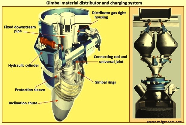
Fig 8 Gimbal material distributor and charging system
Furnace proper
The furnace proper is the main reactor vessel of the BF ironmaking process. Its internal lines are designed to support the internal process. Its external lines are designed to provide the necessary systems to contain, maintain, monitor, support, and adjust the internal process.
The BF process is a counter flow process. The process comprises of (i) burden at ambient conditions is placed in the furnace top onto the column of burden within the furnace, (ii) as the burden descends with the burden column, it is heated, chemically modified, and finally melted, (iii) further chemical modifications occur with the molten material, (iv) the molten products are extracted near the bottom, (v) melting of the burden material and extraction result in the descent of the burden column and the need for replenishment of the burden at the top, (vi) hot blast air is introduced through tuyeres near the bottom, (vii) BF gases are generated in front of the tuyeres and ascend through the burden and chemically modify the descending burden as well as themselves get chemically modified and cooled, (viii) BF gas (and dust) is extracted near the top of the furnace, and (ix) heat is extracted from the vessel in all directions (primarily through the lining cooling system) and along with the BF gas, liquid iron and liquid slag. Fig 9 shows cross section and types of BF.
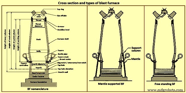
Fig 9 Cross section and types of blast furnace
Furnace type – Furnaces are constructed to be mantle supported or free standing. Mantle supported BFs characteristically have a ring girder (mantle) located at the bottom of the lower stack of the furnace. The mantle is supported in turn by columns which are on the main furnace foundation. The hearth, tuyere breast, and bosh are also supported by the foundation. Furnaces with mantle support column tend to have restricted access and reduced flexibility for improvements in the mantle, bosh, and tuyere breast areas.
Since thermal expansion is a major consideration in furnace shell design, the mantle style of furnace provides an interesting design consideration. The mantle support columns are relatively cool. The mantle tends to maintain a constant height, throughout the furnace campaign with respect to the furnace foundation. Thermal expansion of the stack due to process heat is considered to be based at the ‘fixed’ mantle (i.e. the top of the furnace raises with respect to the mantle). The effective height of the bosh, tuyere breast, and hearth wall shells (supported on the furnace foundation) increases due to the thermal expansion of the shell caused by the process heat. The lower portion of the furnace lifts upwards towards the fixed mantle. Hence, the provision of an expansion joint of some type is needed at the bosh / mantle connection or somewhere appropriately located in the lower portion of the furnace.
Free standing furnaces have been developed to eliminate the column and permit the installation of major equipment and furnace cooling improvements. This furnace type has a thicker shell for structural support. Installation and maintenance of a reliable cooling and lining system is necessary in order to sustain the structural longevity of the shell.
Two variations of the free standing furnace have been used. One type provides for a separate structural support tower to carry the furnace off-gas system and charging / hoisting system load. The other type (while it does employ a separate support tower for shell replacement purposes during relines) uses the furnace proper to support the off-gas system and charging / hoisting system loads. Special consideration to the furnace shell design is to be made regardless of the furnace type. The furnace vessel is subjected to internal pressures from the blast and gas, burden, liquid iron and slag. Dead and live load during all operating, maintenance, and reline stages are to be considered as well.
Furnace zones – The major zones of the furnace proper are (i) top cone, (ii) throat, (iii) stack, (iv) mantle / belly, (v) bosh, (vi) tuyere breast, (vii) hearth walls, (viii) hearth bottom, (ix) foundation.
Top cone – The top cone or dome is the uppermost part of the furnace proper. It supports the furnace top charging equipment, and the BF top gas collection system. Stock rods (stockline recorders or gauges) are normally placed here to monitor the upper level of the burden in the furnace. These devices are the units which provide the permissive or indication signals to charge the next scheduled burden input to the furnace. Typically, they are weights lowered by special winches, or microwave units. Some furnaces incorporate radio-active isotope emitters and detectors mounted in the furnace throat to monitor the burden level. Infrared camera can be installed in the top cone to monitor the BF top gas temperature distribution as it escapes the furnace burden stockline.
The top cone is the coolest zone of the furnace proper but can be exposed to extremely high temperatures if burden ‘slips’ (rapid, uncontrolled burden descent after a period of unusual lack of descent). The newly charged burden falls through this zone and the BF top gas is carried away from this section.
Throat – Steel wear plates or armour are installed in this zone. Here, abrasion of the furnace lining from the charged burden is the prime cause of deterioration. Furnace operators work to maintain the upper level of the burden (the stockline) in this region. Movable armour can be installed in this area in order to deflect the burden falling from a large bell. With the installation of the BLT, wear of the stockline area can be greatly reduced. Some BF users select to eliminate the armour plates and use an abrasion resistant refractory lining instead.
Stack – The stack (sometimes called shaft or the ‘in-wall’) is the zone between the mantle or belly on a free standing furnace and the stockline area. Smooth, uniform lines (the process ‘working surface’) of the stack are essential for uniform and predictable burden descent, BF gas ascent, and stable process control throughout the furnace campaign. Process considerations dictate a larger diameter at the base of the stack than at the top. Typical stack angles are in the range of around 85 degrees from the horizontal.
Mantle / belly – The mantle or belly area provides the transition between the expanded stack and bosh sections. Maintenance of the effectiveness of the cooling / lining system is particularly important for the mantle type furnace in order to protect the mantle structure. Thermal protection is important for the free standing furnace type as well. However, the free standing design is less complicated and more accessible in this area.
Bosh – The bosh area lies between the tuyere breast and the mantle / belly of the furnace. The bosh diameter increases from bottom to top. The inclination of the bosh permits the efficient ascent of the process gases and has been found to be necessary in order to provide the needed zone service life (the process gases are extremely hot and internal chemical attack conditions are severe). Typical bosh angles are in the range of around 80 degrees from the horizontal. Boshes are of two basic types, namely (i) banded and (ii) sealed. They can be cooled by different techniques.
Banded boshes are found in older mantle supported furnaces (they cannot be applied to free standing furnaces). A number of steel bands are placed in incrementally increasing diameters (smallest at the bottom of the bosh and largest at the top) and are tied together with connecting strips. Gap between the bands permits the introduction of copper cooling plates. Ceramic brick lining is to be used as air infiltration results in oxidation of carbon based linings. Gas leakage through the banded bosh can be high. This type is not suitable for BFs with high blast pressure / high top pressure. Banded boshes provide adequate flexibility to eliminate the requirement for a shell expansion joint in the lower portion of the furnace.
Sealed boshes, using continuous steel shell plate instead of separate bands, are employed to permit the use of improved cooling / lining systems, higher furnace operating pressures, and the free standing furnace type. Sealed boshes retain valuable gases with the furnace, hence improving the metallurgical process. As well, the seal bosh, since it precludes air entry into the lining, supports the use of carbon based refractories.
Tuyere breast – Hot blast air is introduced to the furnace through tuyeres (water-cooled copper units) located within the tuyere breast. The number of tuyeres needed depends upon the size (production capacity) of the furnace. The tuyere breast diameter, tuyere spacing, and number of tuyeres are influenced by the expected raceway zone size in front of each tuyere.
Tuyere stocks (Fig 10) convey the hot blast air from the bustle pipe to the tuyeres. The tuyeres are supported by tuyere coolers (water-cooled copper units) which are in turn supported by steel tuyere cooler holders (either welded or bolted to the furnace shell). Special consideration are to be made in the tuyere breast shell and lining design in order to maintain effective sealing of the different components in order to prevent escape and loss of the furnace gases.
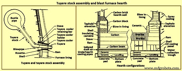
Fig 10 Tuyere stock assembly and blast furnace hearth
Hearth – The hearth (Fig 10) is the crucible of the furnace. Here, hot metal and liquid slag are collected and held until the furnace is tapped. The hearth wall is penetrated by tap holes (frequently called iron notches) for the removal of the collected hot metal and liquid slag. The number of tap holes is dependent upon the size of the furnace, hot metal, and liquid slag handling requirements, physical and capital constraints etc.
Several furnaces are equipped with a slag or cinder notch (normally one per furnace, although some furnaces can have two). The slag notch opening elevation is normally sufficiently higher than the iron notch elevation. In earlier days, when slag volumes were high, the slag was flushed from the slag notch periodically. This simplified the iron / slag separation process in the cast house. More commonly now, however, the slag notch is retained solely for initial furnace set-up procedures or for emergency use in case of iron notch or other furnace operating problems.
Hearth bottom – The hearth bottom supports the hearth walls and is flooded by the iron within the furnace. As the campaign progresses, the hearth bottom lining wears away to a fixed equilibrium point. The remaining refractory contains the process and with sufficient cooling or inherent insulation value protects the furnace pad and foundation.
Cooling system
The application of specific cooling techniques to individual furnace zones is dependent upon several factors such as campaign life expectancy, furnace operational philosophy, burden types, refractories, cost constraints, physical constraints, available cooling media, and preferences etc. Different cooling techniques can be provided for different zones to assist the lining to resist the specific zone deterioration factors. Normally, the provision of adequate cooling capacity is necessary in each of the applicable furnace zones if the lining system located there is to survive. Where the thermal, chemical, and to some extent the abrasive conditions of the process are extreme, sufficient cooling is to be provided to maintain the necessary uniform interior lines of the furnace and to protect the furnace shell.
Typically, the top cone and throat areas of the furnace are not cooled. The hearth bottom can be ‘actively’ cooled by under hearth cooling (air, water, or oil media) or ‘passively’ cooled by heat conduction though the hearth bottom lining to the hearth wall. The basic cooling options for the balance of the furnace are (i) no cooling (typically the upper portion of the stack is not cooled in several furnaces, (ii) shower or spray cooling, (iii) jacket or channel cooling, (iv) plate cooling, and (v) stave cooling.
Shower or spray cooling – Water is directed by sprays or by overflow troughs and descends in a film over the shell plate. Effective spray nozzle design, numbers and positioning are important for proper coverage and to minimize rebound. Proper deflector plate design is necessary to ensure efficient cooling water distribution and to minimize splashing. Shower cooling is frequently employed in the bosh and hearth wall areas. Spray cooling is normally applied for emergency or back-up cooling, primarily in the stack area. Exterior shell plate corrosion and organic fouling are common problems which can disrupt water flow or insulate the shell from the cooling effect of the surface applied cooling. Water treatment is an important consideration to retain effective cooling.
Jacket or channel cooling – Fabricated cooling chambers or indeed structural steel channels or angles are welded directly to the outside of the shell plate. Water flows at low velocity though the cooling elements in order to cool the shell and the lining. Jacket or channel cooling is frequently applied to the hearth walls, tuyere breast, and bosh areas. Scale build-up on the furnace shell and debris collection in the bottoms of the external cooling elements can compromise the cooling effectiveness. Hence periodic cleaning of the cooling elements is necessary.
The critical area of concern in the cooling schemes mentioned so far is the necessity for the shell plate to act as a cooling element. If extreme heat loads are acting upon the inside face of the shell, then there exist an extremely high thermal gradient across the shell. This effect results in high thermally induced shell stresses and eventual cracking. The cracks start from the inside of the furnace and propagate to the outside. The cracks remain invisible (other than a ‘hot spot’) until they fully penetrate the shell plate. Through cracking of the shell plate results in the leak of the BF gas, exposed shell carburization, and disruption of the cooling effect (particularly spray or shower cooling). Shell cracking into a sealed cooling jacket or channel is difficult to locate and can result in long furnace outage time for repair. Entry of water into the furnace (frequently when the furnace is off-line and internal furnace gas pressure cannot prevent entry of cooling water though shell cracks) can have detrimental effect upon the furnace lining. Water in the furnace can be potentially dangerous due to explosion risk (steam or hydrogen). Since shower and jacket cooling rely on the shell plate to conduct the process heat to the cooling media, the plate and stave cooling are configured to isolate the shell from process.
Plate and cigar cooling – Installation of cooling elements though the shell of the furnace (Fig 11) has been a major furnace design improvement resulting in effective cooling of the furnace lining and protection of the shell plate. Cooling is provided along the length of the cooling element penetration into the lining. The inserted elements provide positive mechanical support for the refractory lining. Typical cooling plate manufacture is cast high conductivity copper. Single or multiple passes of cooling water can be incorporated. Cooling boxes with larger vertical section have been produced from cast steel, iron, or copper.
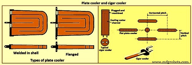
Fig 11 Plate cooler and cigar cooler
Cigar type (cylindrical) coolers (Fig 11) of steel and /or copper have also been successfully used. The philosophy of dense plate cooling (i.e. vertical pitch of 350 mm to 400 mm centre-to- centre, and horizontal pitch of 600 mm (centre-to-centre) has improved the cooling effect and increased lining life.
Copper cooling plates have traditionally been anchored in the shell plate with retainer bars or bolted connections to permit ready replacement if plate leakage occurs. More recently, plates have been designed with steel sections at the rear of the plate for welding directly to the steel shell. While sometimes taking longer to replace, this type provides a positive seal against BF gas leakage. Plate coolers are typically installed in areas above where the liquid iron collects in the furnace. Hence the mid-point of the tuyere breast, right up to the underside of the throat armour is the range of application.
Stave cooling – Cast iron cooling elements (Shannon plates or staves) have been used for several years in the bosh and hearth wall areas. These castings have cored cooling passages of large cross-section. While their service life have been not remarkable in the bosh, multiple campaigns have been normal for the hearth wall. These staves frequently suffered from low flow rates of marginal quality cooling water (scaling and debris deposition / build-up) and sometimes casting porosity. Water leaks into the hearth wall can be a considerable problem.
In the 1950s, the then USSR developed a new type of stave cooler (Fig 12) and ‘natural evaporative stave cooling’. For this design, castings were of gray cast iron containing steel pipes for water passes. The pipes were coated prior to casting to prevent carburization of the cooling pipe and metallurgical contact with the stave body material. The staves were installed in horizontal rows with the furnace and the cooling pipes projected through the shell. Vertical column of staves were formed by the inter-connection of the projecting pipes from one stave up to the corresponding stave in the next row. Staves can be applied to all the walls in the zones below the armour. Staves in the hearth wall and tuyere breast are supplied with smooth faces. Staves in the bosh, mantle / belly and stack normally have rib recesses for the installation of refractory.
Evolution of the stave cooler design has been dramatic. Staves in the higher heat load areas are now typically cast from ductile iron for improved thermal conductivity and crack resistance. While early stave design used castable refractory (installed after stave installation within the furnace), ribs now normally incorporate refractory bricks, either cast in place (with the stave body at the foundry) or slid and mortared in place prior to installation in the furnace. Fig 12 shows stave cooler and generations of stave development.
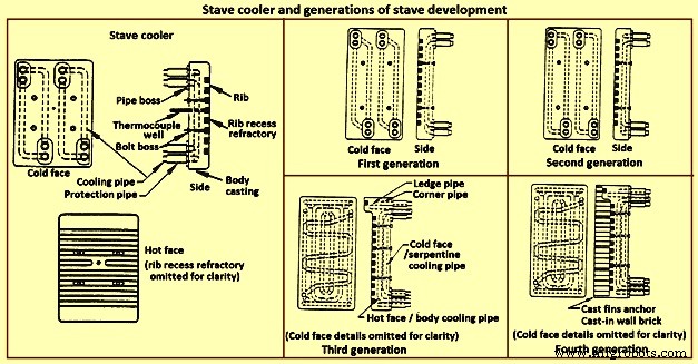
Fig 12 Stave cooler and generations of stave development
Staves are normally expected to retain a refractory lining in front for some time. After loss (expected) of the lining the staves are designed to resist the abrasive effects of descending burden and ascending dirty gas. As well, they are to absorb the expected process heat load and resist thermal load cycling and shock. Four generations of staves (Fig 12) are normally recognized in the industry.
First generation staves are no longer normally used. These staves have four cooling body circuits (with long radius bends which do not effectively cool the stave comers. These staves are made of gray iron castings with castable rib refractory. Second generation staves have four cooling body circuits with short radius bends for improved comer cooling. These staves are made of ductile iron castings with cast-in or glued-in rib bricks. Third generation staves have two-layer body cooling incorporating four or six cooling body circuits (stave hot face) and one or two serpentine cold face circuits (stave cold face) for additional or back-up cooling in the event of hot face circuit loss. These staves have additional edge cooling (top and bottom). The more frequent use of these staves is as cooled ledges to support a refractory lining. These staves have cast-in or mortared-in rib bricks. Fourth generation staves have two-layer cooling (similar to third generation). These staves have cooled ledges and cast-in wall brick lining eliminating the need for a manually placed interior brick lining.
Staves incorporating hot face ledges are more effective in retaining a brick lining than the smoother rib faced bricks. However, once the brick lining disappears, the ledges are very exposed within the furnace. The ledges disrupt burden descent and gas ascent. Exposed ledges tend to fail quickly. They are frequently serviced by cooling water separate from the main stave cooling circuit(s). In this way leaking ledge circuits can be more easily located or isolated. Some stave manufacturers are now providing separate ledge castings so that ledge cracking and loss does not damage the parent staves. As well, there is some present change in philosophy to abandon the application of ledges entirely.
Variations of the basic stave generation types are common. For example, staves of fourth generation type utilizing a refractory castable for the wall ling have been employed successfully. Alternatively, brick linings have been anchored to the stave bodies. Such approaches can be used to substitute for brick support ledges.
A ‘fifth’ generation of staves design has been the developed. It is the copper stave (Fig 13). The development of copper staves was carried out both in Japan and Germany for use in the region of bosh, belly, and lower stack to cope with high heat loads and large fluctuations of temperatures. While Japan has gone for cast copper staves, German copper staves are rolled copper plates having close outer tolerarnces and with drilling done for cooling passages. Drilled and plugged copper staves are typically designed for four water pipes in a straight line at the top and four water pipes in a stright line at the bottom. Materials for internal pipe coils include monel, copper, or steel. Unlike cast iron staves, copper staves are intended to be bonded to the cooling pipe.
The development of the cast-in copper stave has considered the following aspects. As per the first aspect, for the prevention of deformation, appropriate design of the stave length and bolt constrained points is important. The first aspect is that the use of the cast-in steel pipe copper stave with its own design is beneficial for effectively reducing the risk of deformation. Fig 13 shows the constrained points of a rolled copper stave and the cast-in steel pipe copper stave. A rolled copper stave is constrained to the shell by mounting bolts and pins. To prevent the weld at the base of a rising pipe from being damaged by stresses, rising piping is connected to the shell by an expansion joint. Due to this structure, the upper and lower ends of the staves are freely displaced, causing the staves to be easily deformed. The large thermal load which is repeatedly applied to the copper stave in the course of the fluctuation in the BF operations etc., causes plastic strain to be gradually accumulated, and results in large deformation. There are cases in which the deformation at the upper end has reached 50 mm or more and a weld has been broken, under the condition of an overly long stave, an in-appropriate bolt position, or high heat load exceeding the design condition.
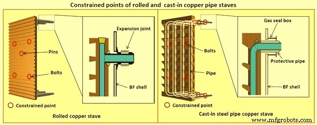
Fig 13 Constrained points of rolled and the cast-in pipe copper stave
Presently, the most popular type of copper stave is the rolled copper stave, the manufacturing process of which involves drilling holes on a copper plate. The water channel ends of these staves are plug-welded. The cast-in steel pipe copper stave, which has been developed, is made by casting bent steel pipes into the copper, a completely different manufacturing process from that of the conventional rolled copper stave. This unique manufacturing method has enabled achieving high energy efficiency and long life of BFs, which cannot be achieved using the rolled copper stave.
Natural evaporative stave cooling (NEVC) is a technique where boiler quality water is introduced into the bottom row of staves and flows by natural mean up the vertical cooling circuits. As the process heat conducts through the stave and cooling pipe into the water, the water in turn heats up. As the water warms, it expands. Since cooler water is being introduced below, the warm water tends to move upwards. At some point in the vertical cooling circuit, the water is at the boiling point. As the water changes its phase to steam, due to the latent heat of vapourization, additional heat is absorbed (driving the phase change). After boiling begins, two-phase flow (water and steam mixture) ascends the cooling pipes to the top of the furnace. Normally located on the furnace top platform are steam separator drums used to extract and vent the steam to atmosphere. Make-up water is introduced to the drum (to replace the discharged steam). The water is piped back by gravity to the furnace bottom and is fed once more to the staves. This cooling technique is very efficient and has low operating costs. There is no pumping equipment. The improvements in this system has been to boost the flow of the cooling water with recirculating pumps (forced evaporative cooling, FEVC) in order to ensure uniform cooling water flow and to cool the recirculating water (forced cold water cooling – FCWC). Both of these approaches have resulted in improved stave and lining life.
Staves provide an excellent protection for the shell plate throughout their service life (which is extended while the interior brick lining remains in place). Stave application has been implemented in all areas of the furnace from hearth wall up to and including the upper stack.
One drawback for conversion of an existing plate cooled furnace to stave cooling can be the cost of a new shell. However, if the existing shell is already in distress and is to be replaced in any event, the conversion cost is not a major factor.
Cast house
The cast house (Fig 14) is the area or areas at the BF where equipment is placed to safely extract the hot metal and liquid slag from the furnace, separate them, and direct them to the appropriate handling equipment or facilities. The hot metal and liquid slag are removed from the furnace through the tap hole. Only infrequently today slag is flushed from the slag notch. The equipment for tap hole is to be reliable and need minimum maintenance. Furnaces typically tap eight times to eleven times per day.
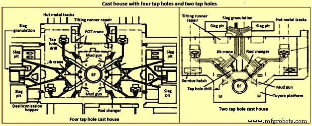
Fig 14 Cast house with four tap holes and two tap holes
Mud gun – The mud gun is used to close the tap hole after tapping is complete. A quantity of the tap hole mass is pushed by the mud gun to fill the worn hole and to maintain a quantity of the tap hole mass (the mushroom) within the hearth. The mud gun is normally held in place on the tap hole until the tap hole mass cures and the tap hole is securely plugged. A hydraulic mud gun uses hydraulic power to swing, hold, and push the tap hole mass. Typical injection pressure of tap hole mass is of the order of 20 MPa to 25 MPa, permitting it to push viscous mass into the furnace operating at high pressures. The hydraulic gun is held against the furnace with the equivalent of 15 tons to 35 tons of force. This type of mud gun can be swung into place in one motion.
An electro-mechanical gun has three separate electric drives for unit swing, barrel positioning, and ramming. Hence several separate motions are needed for accurate positioning of the mud gun at the tap hole. Tap hole mass injection pressure is in the range of only 5 MPa to 8 MPa. The electro-mechanical mud gun is latched to the furnace to keep it in place during plugging.
Tap hole drill – Tap hole drill is used to bore a hole though the tap hole clay into the hearth of the furnace. A drill unit is swung into place hydraulically and held hydraulically in the working position. A pneumatic motor feeds the hammer drill unit (with an attached drill rod and bit) into the hole. Compressed air is fed down the centre of the drill rod and the drill bit to cool the bit and blowout the removed tap hole mass. When the tap hole drill rod has penetrated into the hearth, the drill rod is retracted and the drill swings clear of the hot metal stream.
Soaking bar technique – The application of the soaking bar practice has improved the tapping process. When the tap hole mass is still pliable after plugging, a steel bar is driven into the tap hole by the tap hole drill. While the bar sits in place during the time between casts, it heats up by conduction from the hearth hot metal. This permits curing of the tap hole mass along its entire length (as opposed to curing with the furnace and setting at the outside near the furnace cooling elements). The cured tap hole mass is more resistant to erosion during tapping, hence improving tap flow rate control. Less tap hole mass is needed to replug the hole. When the tap hole is to be opened, a clamping device and a back hammering device on the tap hole drill extract the rod. The timing for tap hole opening can be more easily controlled (predicted) than by conventional drilling. This feature is important for smooth furnace operation and for scheduling of hot metal delivery to downstream facilities.
Same side tap hole equipment – Mud gun and drills have normally been installed on opposite sides of the tap hole. Design development has permitted installation of these equipments on one side of the tap hole. The drill swings over the mud gun or vice versa. This type of installation facilitates improved access for tap hole and trough maintenance and the improved application of trough and tap hole area flue collection.
With the advent of tuyere access platforms to facilitate tuyere and tuyere stock inspection and replacement, the headroom available for the tap hole equipment has diminished. However, same side tap hole equipment installations can be achieved with low headroom (for example 2.2 metres).
Trough and runner system – Typical hot metal and slag tapping rates are in the range of 4 to 6 tons per minute and 3 to 5 tons per minute, respectively. The trough and runner systems are to be designed to properly separate the iron and slag and to convey them away from the furnace for flow rates within the normal flow rate range and for unusual peak flow rates.
The hot metal trough (Fig 15) is a refractory lined tundish located in the cast house floor and designed to collect iron and slag after discharge from the furnace. The hot metal flows down the trough, under a skimmer and over a dam into the hot metal runner system. The hot metal level in the trough is dictated by the dam. Proper dam design submerges the lowest portion of the skimmer in the hot metal pool. The slag, being lighter than the hot metal, floats down the trough on top of the hot metal pool. Since it cannot sink into the hot metal and through the skimmer opening, it pools on top of the hot metal until sufficient volume collects to overflow a slag dam and run down the slag runner. At the end of the tapping, the slag runner dam height is lowered to drain off most of the slag. The residual hot metal is retained in the trough to prevent oxidation and thermal shock of the trough refractory lining.
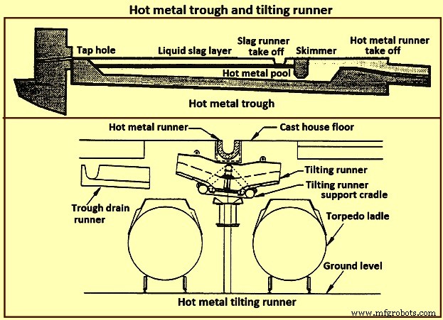
Fig 15 Hot metal trough and tilting runner
When maintenance of the trough lining is needed, the hot metal pool can be dumped by removing the hot metal dam, or by opening a trough drain gate, or by drilling into the side of the trough (at its lowest point) with a drain drill. The trough bottom is normally designed with a 2 % (minimum) slope for effective draining. Trough cross-section and length design are important for effective iron and slag flow pattern, retention, and separation. A good trough design results in hot metal yield improvements. Effective trough lining and cooling techniques are important for lining life, hot metal temperature, and cast house structural steel and concrete heat protection considerations. Troughs traditionally were contained in steel boxes ‘buried in sand’ in the cast house floor system. Improved trough design incorporates forced or natural air convection or water-cooling.
Cast house practice needs the runners to be as short as possible. This minimizes temperature loss of hot metal and reduces runner maintenance and flue generation. Shorter runners can also result in reduced capital expenditure for cast house building installation or modification. Since the runners are to slope away from the furnace, the cast house floor normally follows the same slope as the runners.
Slag runners are normally designed with a 7 % (minimum) slope. Slag can be directed to (i) slag pots for railway or mobile equipment haulage to a remote site for dumping, (ii) slag pits adjacent to the furnace for air cooling and water quenching prior to excavation by mobile equipment, and (iii) granulation facilities adjacent to the furnace for conversion of the liquid slag to granulated slag. Granulation units are provided with systems to eliminate flue emissions associated with environmental issues.
Hot metal runners are normally designed with a 3 % (minimum) slope. Hot metal is normally directed to hot metal transfer ladles (torpedo cars / open top ladles) for movement to the steel melting shop or pig casting machines. While normal practice used is to have one iron runner system with diverter gates directing the hot metal to different pouring positions, each with a ladle. Application of the tilting runner practice has been beneficial. A tilting runner is normally with an electrical motor-driven actuator (with a manual hand wheel back-up), and is tilted at around 5 degrees to divert the hot metal. A pool of hot metal is held in the tilting runner to minimize splashing and refractory wear. When one hot metal ladle has been filled, the runner is tilted to the opposite side to fill the other ladle. If needed, a locomotive removes the filled ladle and spots an empty ladle in its place. This operation can be done without plugging the furnace. When the tapping is finished, the tilting runner is tilted an additional 5 degrees to dump its pool of hot metal into the ladle.
Modern cast house design includes flat floors, where the runner is fully covered and is fitted flush with the floor. This allows safer and easier use of mobile vehicles in the cast house area. The use of radio controlled equipment and other devices have helped to reform cast house work, and these, along with effective emission control systems, have improved working conditions. As the BF hearth diameter is increased, there is a resulting need to increase the size of the cast-house. Large BF are normally designed with four tap holes (Fig 14). With a four top-hole configuration, the cast-house arrangement needs to provide sufficient space for movement around the floor itself. There is no design issues associated with this requirement as long as there is the necessary space provided in the site plan. Increasing the size of the cast-house in terms of floor plan does not represent a radical change in design philosophy which can pose a challenge the furnace designer. An efficient and strictly controlled tapping is necessary for ensuring a stable operation and high productivity of the BF.
Emission control
Fume collection requirements and applications appear to vary considerably around the globe. BFs presently have full, partial, or even no cast house fume collection system. Exhaust fan and bag house capacity of the order of 9,000 cubic meter per minute (cum/min) to 11,500 cum/min (depending upon operation and design practices) is typical for full flue capture of a two tap hole cast house installation (for trough runners and tilting runners).
Proper design and application of flue collection runner covers can facilitate cast house access (i.e. flat floor configuration using steel slabs or plates) for personnel and mobile equipment crossover. Runner covers can also reduce hot metal temperature loss and improve runner refractory longevity.
Some furnaces use flame suppression which eliminates the oxygen in the air directly over the trough and iron runners. Products of combustion prevent oxidation of the hot metal surface reducing visible particulate and flues.
Other aspects of BF design
It is necessary that complete study of every element in the process chain, from raw materials delivery to hot metal consumption is made to ensure that there are no ‘bottle necks’ in the system which can prevent the furnace from meeting the goals of its installation. While designing the BF, thought process is to be used to develop the furnace design and some alternatives are to be considered before freezing the design. During the designing of the furnace, those furnace equipments are to be selected which best meet the needs of the furnace operation.
The furnace design is to ensure (i) the furnace is capable of meeting the operational goals of production, productivity (tons per day per cubic metre of working volume), specific consumptions (kilograms per ton of hot metal), and product quality in cost effective manner, (ii) the furnace has the flexibility to accept and absorb the changes in the quality of the raw materials, and (iii) the furnace is capable of achieving the desired campaign life both with respect to time and the total production.
Financial justification is the over-riding consideration for the design. For this purpose, the economic study is to be very extensive. Further, the furnace design is to include latest technological developments so that the furnace does not become technologically outdated during its entire campaign.
The working volume of the furnace is the internal volume of the furnace calculated between the tuyeres and the stock line. Hearth productivity of the furnace is rated in tons per day per cubic metre of active hearth volume. Active hearth volume is the internal volume of the furnace calculated between the tuyeres and the tap hole. Active hearth volume is a measure of the holding capacity of the furnace for the liquids produced in the working volume (above the tuyeres). Hence, the tons per day per cubic metre of active hearth volume is a measure of the specific capacity (through-put per unit volume) of the hearth of the BF.
The design of the hearth is very important since it has a strong effect on the furnace operation. The furnace operation gets affected since the hearth liquid levels change rapidly which cause variations in gas flow pattern, gas utilization, and blast pressure. Also, because of these rapid changes in liquid level, there can be jamming / burning of the tuyeres which affect the blowing of the furnace.
The furnace hearth volume also determines the controls the operator is to exercise during furnace operation. For a very good hearth liquid level control, the high through-put furnace need around 90 % time spent in tapping. To make this time of tapping possible, cast floor is to be designed properly.
The furnace lining and cooling system needs special attention so that it does not pose any problem during the entire campaign of the BF. The selection of refractories, cooling elements, and internal furnace geometry is very important in this respect. Copper staves in this respect are expensive but they are very economical in comparison to the alternatives. Carbon lining of the hearth is very important for the long life of the hearth. The refractory lining thickness of the stack has implication on the furnace working volume.
The production needed normally determines the size of the BF. However, for the sizing of the BF, the raw materials, the product chemistry, and even operating philosophy are important. While the furnace size has implication on the capital cost, the productivity improvement has implication on the operating cost. The specific productivity of the furnace is to be determined for the determination of the size of the BF needed to produce the required quantity of hot metal. From the wide range of possible operating rates, the working volume of the furnace is to be calculated. Productivity and hence the furnace size is also to be based on the fuel rate. The fuel rate is dependent on the quality of raw materials, hot blast parameters, hot metal quality, and the operating philosophy.
The size is the most important factor for the determination of the BF productivity. However, there are other factors which also influence the BF productivity. The most important of these factors include (i) hot blast temperature and pressure, (ii) high top pressure, (iii) oxygen enrichment of the air blast, (iv) injection of auxiliary fuel at the tuyere, (v) prepared burden (sinter, pellets etc.), (vi) Fe content of the ferrous burden, (vii) ash in coke, (viii) quality of the coke, (ix) moisture content of the burden, (x) direct charging of fluxes (lime stone, dolomite etc.) in the BF, (xi) content of fines in the burden, (xii) quality of hot metal to be produced, (xiii) burden distribution control in the furnace, and (xiv) level of automation and control in the furnace.
The availability of furnace equipment, provision of stand-by equipment, and the maintenance philosophy are important factors which have high influence on the annual production from the BF. Further, incorporation of safe and healthy working practices during the operation of BF in the design of the BF is important which has a high influence on the furnace productions. In this regards, safety interlocks are to be provided at all the places where there exist a chance of unsafe operating practices to take place.
Processus de fabrication
- Le laitier de haut fourneau et son rôle dans le fonctionnement du four
- Aspects importants de la conception du haut fourneau et des équipements auxiliaires associés
- Système d'automatisation, de mesure et de contrôle du processus de haut fourneau
- Génération et utilisation de gaz de haut fourneau
- Productivité des hauts fourneaux et paramètres d'influence
- Exploitation du laitier à haute teneur en alumine et du haut fourneau
- Système de refroidissement de haut fourneau
- Salle de coulée de haut fourneau et son fonctionnement
- Fabrication du fer par haut fourneau et émissions d'oxyde de carbone