Nanohelix à double porte en tant que nouveau super-réseau binaire accordable
Résumé
Nous étudions théoriquement le problème d'un électron confiné dans une nanohélice entre deux grilles parallèles modélisées comme des fils chargés. Le système de nanohélice à double grille est un super-réseau binaire avec des propriétés très sensibles aux tensions de grille. En particulier, la structure de bande présente des croisements de bandes d'énergie pour certaines combinaisons de tensions de grille, ce qui pourrait conduire à des phénomènes quasi-relativistes de type Dirac. Notre analyse des transitions optiques induites par la lumière polarisée linéairement et circulairement suggère qu'une nanohélice à double porte peut être utilisée pour des applications optoélectroniques polyvalentes.
Introduction
Des gastéropodes spiralés fossilisés que le premier auteur collectionnait avec enthousiasme dans son enfance, à la structure entrelacée de l'ADN qui a sans aucun doute défini autrefois ces créatures préhistoriques, la géométrie de l'hélice est répandue dans toute la nature [1]. Inspiré par les fonctionnalités complexes attribuées aux formes des biomolécules naturelles [2–6], on s'attend à ce que d'autres systèmes possédant des géométries hélicoïdales adaptées à la nanotechnologie produisent une physique riche et contribuent à de nouvelles applications. Au cours des trois dernières décennies, des progrès remarquables dans les techniques de nano-fabrication ont conduit à la réalisation de nanohélices dans une multitude de systèmes différents, notamment InGaAs/GaAs [7], Si/SiGe [8], ZnO [9–11], CdS [ 12], SiO2 /SiC [13, 14], et du carbone pur [15-20], ainsi que des semi-conducteurs II-VI et III-V [21] (pour l'état actuel de l'art, voir les références [21-26]). Par conséquent, une pléthore de phénomènes est attendue dans de telles structures, allant des propriétés de transport exotiques comme le pompage de charge quantifié topologique [27, 28], la supraconductivité [29] et le filtrage de spin [30–32], à l'électronique moléculaire et nanomécanique extensible [33, 34] en raison des effets piézoélectriques [35], des applications de détection [36, 37], du stockage d'énergie [38] et d'hydrogène [39], et des transistors à effet de champ [40, 41].
La fascination pour les dispositifs basés sur la nanohélice découle finalement de la périodicité inhérente codée dans la topologie de la structure de l'hélice. En particulier, soumettre une nanohélice à un champ électrique transversal (normal à l'axe de l'hélice) donne lieu à un comportement de super-réseau tel que la diffusion d'électrons de Bragg sur un potentiel super-périodique, conduisant à un clivage d'énergie au bord du super-réseau zone Brillouin entre les états les plus bas accordables linéairement par le champ électrique [42, 43]. Ce comportement peut entraîner des oscillations de Bloch et une conductance différentielle négative [44, 45], et peut accentuer le transport polarisé en spin à travers les hélices [31, 46], ainsi que produire une amélioration du dichroïsme circulaire utile dans les applications chiroptiques nanophotoniques [47]. Ce système constitue un super-réseau unaire et ouvre en outre la possibilité d'utiliser des nanohélices comme diodes tunnel ou diodes Gunn pour la multiplication de fréquence, l'amplification et la génération ou l'absorption de rayonnement dans la gamme térahertz célébrée [48-51]. Alors que le super-réseau prototype est généralement réalisé dans des hétérostructures de couches semi-conductrices alternées avec différentes bandes interdites intrinsèques, les paramètres du super-réseau nanohélicoïdal sont entièrement contrôlés par le champ externe. Au contraire, les formes des anciens potentiels de superréseau conventionnels sont spécifiques à l'hétérostructure et, bien que robustes, offrent une capacité limitée de manipulation au cours de son exploitation sans l'utilisation de grands champs externes. Par conséquent, l'intérêt de l'utilisation de nanohélices comme super-réseaux au lieu de cela réside dans leur plus grande accordabilité.
D'autre part, avec des super-réseaux semi-conducteurs à hétérostructures (ou bien des structures de super-réseaux photoniques [52-55] et des atomes froids dans des réseaux optiques [56, 57]), on peut créer des cellules unitaires de super-réseaux plus compliquées au-delà du simple puits quantique qui est induit par le champ électrique le long de l'hélice. Même l'extension à un super-réseau binaire [58-60] (où la cellule unitaire se distingue par deux puits quantiques et/ou barrières différents) promet un riche éventail de physique telles que les oscillations de Bloch-Zener [61], qui peuvent à leur tour contribuer aux applications de séparateurs de faisceaux et d'interféromètres accordables [62]. Ainsi, il serait hautement souhaitable de combiner l'accord de champ externe d'un super-réseau à base de nanohélices avec la fonctionnalité supérieure d'un super-réseau binaire.
Dans ce qui suit, nous décrivons un tel système, avec une nanohélice positionnée entre deux fils chargés à grille parallèle alignés avec l'axe de l'hélice. Nous envisageons l'application d'un champ électrique transversal supplémentaire et montrons théoriquement que le potentiel contrôlable par grille et champ constitue un super-réseau binaire le long de l'hélice unidimensionnelle.
Méthodes
Modèle théorique
Commençons par étudier le cas d'une nanohélice circulaire semi-conductrice monoélectronique avec N tours de rayon R , pas p , et la longueur totale L =Np . La nanostructure est positionnée entre deux grilles parallèles modélisées comme des fils chargés avec son axe d'hélice aligné le long du z -axis et avec l'axe et les portes résidant tous sur le même plan que celui représenté sur la figure 1. De plus, nous considérons un champ électrique transversal externe normal au plan de l'axe de la porte \(\mathbf {E}=E_{\bot } \ hat {\mathbf {y}}\) qui peut être utilisé pour briser la symétrie de réflexion du potentiel au-dessus du plan par rapport au potentiel au-dessous du plan. Nous travaillons en coordonnées hélicoïdales décrites paramétriquement via r =(x,y ,z )=(R cos(s φ ),R péché(s φ ),ρ φ ), où la coordonnée angulaire dynamique φ =z /ρ ne dépend que de la distance le long de l'axe de l'hélice avec ρ =p /2π , et s =±1 indique une hélice à gauche ou à droite, respectivement. Dans ce travail, nous considérons une hélice gauche s =1. Dans le cadre du modèle de masse effective, le spectre d'énergie ε ν du ν l'état propre d'un électron dans une hélice sous l'influence de tels potentiels externes se trouve à partir de l'équation de Schrödinger :
$$ -\thinspace \frac{\hbar^{2}}{2M^{*}\rho^{2}}\frac{d^{2}}{d\varphi^{2}}\psi_{\ nu} +\left[V_{g} (\varphi) + V_{\bot} (\varphi) \right]\psi_{\nu} =\varepsilon_{\nu} \psi_{\nu} $$ (1 )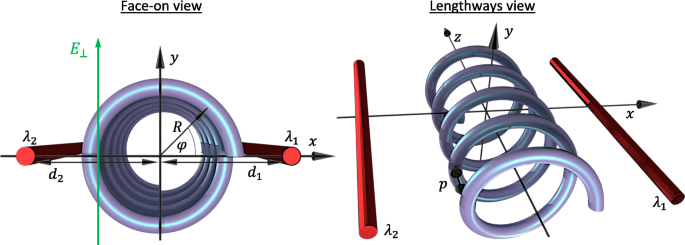
Diagramme de la géométrie et des paramètres du système en perspective frontale et longitudinale. R est le rayon de l'hélice, et d 1 et d 2 sont les distances des fils chargés de l'axe de l'hélice avec des densités de charge λ 1 et λ 2 , respectivement. La coordonnée spatiale φ décrit la position angulaire sur l'hélice de face et est liée au z -coordonner via φ =2π z /p avec p le pas de l'hélice. Un champ électrique transversal E ⊥ est appliqué parallèlement au y -axe
où nous avons renormalisé géométriquement la masse effective de l'électron M e à M ∗ =M e (1+R 2 /ρ 2 ) afin de tout exprimer en fonction de la coordonnée le long de l'axe de l'hélice (rappelons que φ =z /ρ ) ce qui est plus pratique pour les potentiels externes. Ici, V ⊥ (φ )=−eE ⊥ R péché(φ ) est la contribution du champ électrique transverse dirigé le long du y -axe tel que V ⊥ (π /2)<0. Le potentiel des portes est V g (φ )=−e [Φ 1 (φ )+Φ 2 (φ )] avec le potentiel électrostatique ressenti par un électron le long de l'hélice en raison d'un fil chargé individuel donné par Φ i (φ )=−λ i k ln(r i /d i ). Ici, i =1,2 étiquette les fils, λ i est la densité de charge linéaire sur un fil, et \(k =1/2\pi \tilde {\epsilon }\) avec \(\tilde {\epsilon }\) la permittivité absolue. La distance perpendiculaire d'une charge d'essai à partir d'un fil particulier est donnée par \(r_{i}=[d^{2}_{i}+R^{2} + 2(-1)^{i}d_{i }R\cos (\varphi)]^{1/2}\), avec d i désignant la distance correspondante du fil à l'axe de l'hélice. Nous avons défini le potentiel induit par la porte zéro comme étant le long de l'axe de l'hélice. Le potentiel unidimensionnel total V T (φ )=V g (φ )+V ⊥ (φ ) est clairement périodique V T (φ )=V T (φ +2π n ) avec période 2π en général (ce qui correspond à la période de p par rapport à la coordonnée z ). Cette période est significativement plus grande que la distance interatomique et donne lieu à des effets de super-réseau typiques. Cette lettre diffère d'une nanohélice dans un champ électrique transverse (qui peut être reproduit avec V T (φ )=V ⊥ (φ ) ici) principalement en manipulant la maille unitaire répétée du super-réseau via le potentiel de double-grille V g (φ ). Prendre la limite p →0, on revient à la particule sur une image en anneau soumise à deux grilles électrostatiques [63, 64]. Faire l'approximation R /d i ≪1, nous pouvons développer V g (φ ) jusqu'au deuxième ordre en cos(φ ), et en transformant l'Eq. 1 en forme sans dimension nous arrivons à
$$ {\begin{aligned} \frac{d^{2} \psi_{\nu}}{d\varphi^{2}}+\left[\epsilon_{\nu} + 2A_{g}\cos( \varphi) + 2B_{g}\cos(2\varphi) + 2C_{\bot} \sin(\varphi) \right]\psi_{\nu} =0, \end{aligned}} $$ (2)avec les quantités en unités de l'échelle d'énergie \(\varepsilon _{0}(\rho) =\hbar ^{2} / 2 M^{*} \rho ^{2}\) défini comme
$$\begin{array}{@{}rcl@{}} A_{g} &=&\beta\frac{\left(d_{1}^{2} +R^{2}\right)}{ d_{1} R}(1-\gamma), \qquad B_{g} =\frac{\beta}{2}\left(1+\frac{\lambda_{1}}{\lambda_{2}} \gamma^{2}\right), \\ C_{\bot} &=&e E_{\bot} R /2\varepsilon_{0}(\rho), \qquad \qquad \qquad \; \epsilon_{\nu} =\frac{\varepsilon_{\nu}}{\varepsilon_{0}(\rho)}. \end{tableau} $$ (3)Ici, \(\beta =ek d_{1}^{2} R^{2} \lambda _{1} /2\left (d_{1}^{2} +R^{2}\right)^ {2}\varepsilon _{0}(\rho) \) caractérise la contribution de la porte 1 tandis que le paramètre d'asymétrie \(\gamma =\lambda _{2} d_{2} \left (d_{1}^{2 } +R^{2}\right)/\lambda _{1} d_{1} \left (d_{2}^{2} + R^{2}\right)\) caractérise la contribution relative de la porte 2 , avec γ =1 correspondant à des contributions de grille égales au potentiel (d'où A g =0). Il est à noter que l'inévitable asymétrie causée par la difficulté à maintenir d 1 =d 2 peut être compensé en manipulant λ 1 et λ 2 . Dans cette lettre, nous nous limitons à considérer γ ≤1 (qui est |Φ 1 |>|Φ 2 |) car le paramètre d'asymétrie étant supérieur à l'unité peut être mappé à un système équivalent inférieur à l'unité via un simple échange des indices étiquetant les portes et le changement de perspective correspondant φ →φ ±π . Nous ne considérerons également que C ⊥ ≥0 en raison de la symétrie des C négatifs ⊥ par rapport à une telle traduction de coordonnées dans φ , et A g 0, B g >0 (c'est-à-dire uniquement des densités de charges positives sur les fils β>0) car tout paysage potentiel avec des portes chargées négativement peut être reproduit avec la combinaison correcte de paramètres de portes chargées positivement. Sur la figure 2, nous traçons le potentiel sans dimension V T (φ )/ε 0 (ρ ), avec la force du π -composant potentiel périodique fixé à B g =0.2, pour plusieurs combinaisons des paramètres de perturbation de période doublée A g et C ⊥ . On voit que le potentiel externe total induit un super-réseau binaire le long de φ , avec un double puits quantique (DQW) comme cellule unitaire surlignée en bleu. Cela peut prendre des formes qualitativement différentes en manipulant les contributions relatives des portes γ et champ électrique transversal E ⊥ . La cellule unitaire est essentiellement un puits unique sous des contributions de grille équivalentes (γ =1) et aucun champ électrique transversal E ⊥ =0 (comme dans la Fig. 2a pour A g =C ⊥ =0). Correction de E ⊥ =0, avec une contribution plus forte de la grille 1 (γ <1), la cellule unitaire devient un DQW avec différents minima de puits et maxima de barrière dégénérée (Fig. 2b où A g =0.1 et C ⊥ =0). En revanche, maintenir les minima DQW dégénérés et manipuler les deux barrières de potentiel l'une par rapport à l'autre nécessite des contributions de grille symétriques (γ =1) dans un champ électrique non nul E ⊥ ≠0 (Fig. 2c avec A g =0 et C ⊥ =0.1). Combinant des contributions de grille asymétriques (γ <1) avec E ⊥ ≠0 produit un DQW avec différents minima de puits de potentiel et différentes barrières (comme le montre la figure 2d où les deux A g =C ⊥ =0.1). Cela conduit à des comportements qualitativement différents et riches comme nous le verrons dans les sections suivantes.
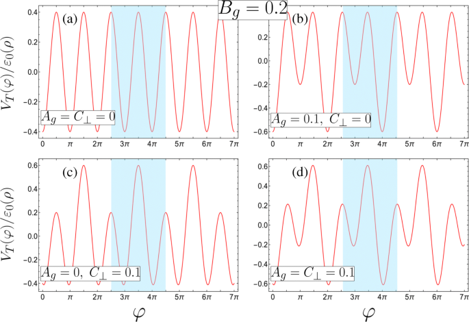
Les quatre configurations potentielles de super-réseau possibles avec les cellules unitaires surlignées en bleu (définies en termes de paramètres sans dimension, voir l'équation 3 pour les exigences correspondantes des paramètres physiques, et toutes avec B g =0.2). un Un super-réseau unaire avec des minima et des maxima dégénérés dans la maille unitaire (A g =C ⊥ =0). b –d Super-réseaux binaires formés à partir de b un DQW asymétrique avec des minima différents et une symétrie de réflexion interne sur l'un ou l'autre des minima en raison de maxima dégénérés (A g =0.1, C ⊥ =0), c un DQW symétrique avec des minima dégénérés uniquement (A g =0, C ⊥ =0.1), ou d un DQW asymétrique avec des minima et des maxima différents (A g =C ⊥ =0.1)
Les solutions sous forme de matrice infinie
Solutions à l'équation. 2 peut être trouvé en termes de fonctions Bloch
$$ \psi_{n,q}(\varphi)=(2\pi N \rho)^{-\frac{1}{2}}e^{iq \varphi}\sum_{m} c^{( n)}_{m,q} e^{im \varphi}, $$ (4)où le q =k z ρ est la forme sans dimension du quasi-impulsion de l'électron k z le long de l'axe de l'hélice, n indique la sous-bande, et le préfacteur résulte de la normalisation en termes de φ :\(\rho \int _{0}^{2\pi N}|\psi _{n,q}(\varphi)|^{2} d\varphi =1\). On utilise l'orthogonalité des fonctions exponentielles en multipliant l'expression résultante par \(e^{im^{\prime } \varphi }/2\pi \) et en intégrant par rapport à φ , où m ′ est un entier, tel que l'on aboutit à un ensemble infini d'équations simultanées pour les coefficients \(c^{(n)}_{m,q}\),
$$ {\begin{aligned} &\left[(q+m)^{2}-\epsilon_{n}\right]c^{(n)}_{m} - \left(A_{g} - i C_{\bot} \right)c^{(n)}_{m-1} - \left(A_{g} + i C_{\bot} \right)c^{(n)}_{m +1}\\ &\quad- B_{g}\left(c^{(n)}_{m+2}+c^{(n)}_{m-2} \right)=0, \ fin{aligné}} $$ (5)où pour plus de clarté le q -la notation en indice a été supprimée, ε n,q ≡ε n et \(c_{m}^{(n)}\equiv c_{m,q}^{(n)} \). L'équation 5 représente une matrice penta-diagonale infinie dans laquelle il est évident que le système est périodique en q , et nous pouvons restreindre nos considérations à la première zone de Brillouin définie par − 1/2≤q 1/2. En l'absence du potentiel de super-réseau A g =B g =C ⊥ =0, les valeurs propres sont alors énumérées par m donné par ε m =(m +q ) 2 et nous reconnaissons m être le nombre quantique de moment angulaire associé à un électron libre sur une hélice. Nous voyons à partir de l'Éq. 5 que lorsque A g =C ⊥ =0 indique uniquement avec Δ m =±2 sont mélangés, tandis que la formation d'une cellule unitaire DQW avec différents minima de puits ou barrières, obtenue via A g ≠0 et/ou C ⊥ ≠0, mélange également les états avec Δ m =± 1. Fait intéressant, le système d'un électron sur une hélice sous un potentiel transverse externe (qui varie sur un tour de l'hélice) est mathématiquement équivalent à un électron sur un anneau quantique percé par un champ magnétique et soumis à un potentiel avec la même forme fonctionnelle variant le long de la coordonnée angulaire; par exemple. voir Réf. [65–67] ou comparer par exemple les Réf. [42–45] avec [68–70]. Pour une bague, le rôle joué par q ici est repris par le flux magnétique. Par conséquent, exactement la même analyse dans ce travail est applicable au problème d'un anneau quantique à double porte [63-66], si l'anneau était percé par un flux magnétique.
Tronquer et diagonaliser numériquement la matrice correspondant à l'Eq. 5 fournit le n e sous-bande énergies propres ε n et coefficients \(c_{m}^{(n)}\) pour chaque valeur de q . Nous appliquons une troncature à |m |=10, sachant que toute augmentation de la taille de la matrice n'entraîne aucun changement appréciable dans les sous-bandes les plus basses.
Résultats et discussion
Structure de bande de nanohélice à double grille
Nous traçons sur la figure 3 la dispersion d'énergie des bandes les plus basses pour plusieurs combinaisons de paramètres. Selon la forme du super-réseau, nous trouvons une variété remarquable dans le comportement de dispersion, et pour certaines combinaisons spécifiques de paramètres, nous découvrons des croisements de bandes d'énergie pour des sous-bandes particulières soit au bord de la zone de Brillouin (Fig. 3a et c) soit à la centre de la zone Brillouin (Fig. 3b et d).
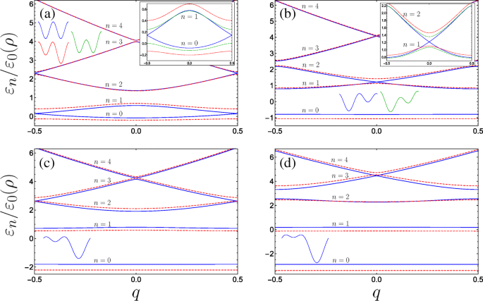
Structure de bande pour système de nanohélice à double porte pour diverses combinaisons de paramètres sans dimension (avec B g =0.4 corrigé partout) :a Tracés bleus pleins (pointillés rouges) A g =0 &C ⊥ =0 (A g =0.2 &C ⊥ =0), l'encart trace en plus le comportement des deux sous-bandes inférieures soumises au champ électrique transverse avec A g =0 &C ⊥ =0,2 comme la courbe verte en pointillés. b Tracés bleus pleins (pointillés rouges) A g =0.63 &C ⊥ =0 (A g =0.8 &C ⊥ =0) où la courbe bleue représente le premier incident de résonance (voir texte) avec des bandes d'énergie se croisant au centre de la zone de Brillouin, l'encart compare le comportement des deux sous-bandes excitées inférieures avec le cas où A g =0.63 &C ⊥ =0,2 comme la courbe verte en pointillés. c Tracés bleus pleins (pointillés rouges) A g =1,26 &C ⊥ =0 (A g =1.5 &C ⊥ =0) où la courbe bleue représente le deuxième incident de résonance avec des lacunes énergétiques se refermant au bord du Brillouin pour les bandes supérieures. d La troisième résonance et les minigaps de sous-bande supérieure se ferment au centre, le bleu continu (rouge pointillé) étant A g =1.9 &C ⊥ =0 (A g =2.2 &C ⊥ =0). Les formes des cellules unitaires sont esquissées, n énumère les bandes, et l'axe des encarts est le même que les graphiques principaux
Perturbation de période doublée à faible champ
Lorsque A g =C ⊥ =0, la maille élémentaire constitue deux puits quantiques équivalents, et par conséquent l'apparition de paires de bandes se touchant aux bords de la zone de Brillouin apparaît naturellement. En effet, prendre un seul puits comme maille unitaire divise par deux la période du super-réseau et entraîne un doublement de la zone de Brillouin − 1≤q 1. Nous observerions alors le diagramme de bande de super-réseau unaire habituel, dans lequel la bande interdite entre le sol et les premières bandes à q =1 est donné ici via la bande interdite entre n =1 et n =2 à q =0 et serait linéaire dans B g de la théorie des perturbations. Néanmoins, nous présentons une description de la structure de la bande à |q |=1/2 dans l'image de la cellule unitaire DQW en utilisant l'algèbre matricielle dans l'annexe. Comme on le voit dans l'encadré de la figure 3a, l'introduction de l'un ou l'autre des termes de potentiel à double période ouvre une bande interdite au bord de la zone de Brillouin. La maille élémentaire des contributions symétriques de grille (A g =0) conserve la forme d'un DQW symétrique sous l'application d'un champ transverse C ⊥ perpendiculaire à l'axe de l'hélice-grille, avec une barrière de potentiel modifiée par rapport à l'autre (indiquée par le croquis DQW vert sur la figure 3a). Tandis que C ⊥ ouvre une bande interdite, la modification de la dispersion est notablement moins sensible qu'à celle d'une grandeur similaire de A appliqué g . Cela se voit à partir de la plus petite bande interdite à |q |=1/2 pour la ligne verte en pointillés dans l'encart de la Fig. 3a (avec A g =0 et C ⊥ =0,2) par rapport à l'écart le plus important pour la courbe rouge en pointillés (qui correspond à A g =0.2 et C ⊥ =0). Pour souligner ce comportement, la figure 4a trace la taille de l'écart énergétique à |q |=1/2 entre les deux sous-bandes les plus basses \(\Delta \varepsilon _{01}^{(q=1/2)}/\varepsilon _{0}(\rho)\) pour B

un Taille de la bande interdite entre le sol et les premières sous-bandes en fonction de A g (C ⊥ ) tracé en pointillés rouges (pointillés verts), ici B g =0.25. Les diagrammes indiquent l'influence des différentes perturbations sur la cellule unitaire DQW isolée et les états propres. b –c Taille de la bande interdite entre les première et deuxième sous-bandes indiquée via un tracé de densité 2D en fonction de ; b Un g et B g pour C ⊥ =0, et c Un g et C ⊥ avec B fixe g =0.25. b Les lignes de contour isoénergétiques adjacentes indiquent une différence de 0,17, avec un écart nul donné par la ligne rouge en pointillés pour \(A_{g}=\sqrt {B_{g}}\), tandis que c la différence est de 0,13 avec un écart nul au centre du plus petit contour en demi-cercle (0,5,0). Les diagrammes esquissent le DQW isolé et les états propres. L'hybridation ne se produit pas entre les s -like et p -comme des états de puits individuels localisés résonants dans b , mais le fait en c en raison du champ électrique changeant une barrière par rapport à l'autre
Passages de bandes énergétiques
Il est assez remarquable de voir que si l'on garde C ⊥ =0 et augmenter A g , alors qu'initialement toutes les dégénérescences sont levées, des bandes d'énergie plus élevées sont amenées à se croiser en alternance entre le centre et le bord de la zone de Brillouin (observez le comportement des courbes bleues et rouges en pointillé progressant de la Fig. 3a à d). Physiquement, nous pouvons comprendre la disparition de la bande interdite en termes d'interactions des fonctions d'onde localisées dans la maille élémentaire. Lorsque le potentiel DQW asymétrique est tel que l'état fondamental dans le puits le moins profond (s -like orbital) est en résonance avec le premier état excité dans le puits plus profond (p -comme orbital), à q =0 en raison de la symétrie de réflexion autour du centre de l'un ou l'autre puits, les parités opposées de ces états empêchent le couplage tunnel habituel entre eux, et par conséquent les états excités construits à partir de ces orbitales coïncident (courbes bleues sur la figure 3b). Cela rappelle les soi-disant s −p résonances dans les réseaux optiques [73, 74]. De même, si les paramètres sont tels que l'état fondamental localisé dans le puits peu profond est en résonance avec un état excité dans le puits plus profond ayant la même parité, alors à |q |=1/2, la présence de la phase de Bloch supprime complètement l'hybridation habituelle entre ces deux états de puits localisés adjacents et la bande interdite est fermée (comme le montre la figure 3c pour la résonance du sol avec le deuxième état excité). Dans le langage de la diffusion du potentiel périodique ; la bande interdite est fermée en raison de l'interférence destructive complète des amplitudes de diffusion de Bragg de second ordre du cos(φ ) les amplitudes de diffusion potentielle et du premier ordre à partir du cos(2φ ) potentiel [75–77].
On peut montrer quantitativement l'existence de croisements de bandes d'énergie (pour un champ électrique transverse nul) à la fois au centre et au bord de la zone de Brillouin en revenant à l'équation. 2, qui est reconnaissable comme l'équation de Whittaker-Hill lorsque C ⊥ =0 [78]. Les fonctions de Bloch Eq. 4 obéissent à des conditions aux limites périodiques torsadées ψ n,q (φ +2π )=exp(2π iq )ψ n,q (φ ). En particulier, lorsque q =0 solutions formelles de l'équation. 2 sont 2π -périodique, alors que lorsque |q |=1/2 solutions sont 2π -antipériodique (et donc on cherchera 4π -solutions périodiques). Plus précisément, l'Éq. 2 avec C ⊥ =0 peut être mappé à l'équation d'Ince [79, 80], qui est quasi-exactement résoluble, en exprimant la fonction d'onde comme le produit de la solution asymptotique de l'équation. 2 et une fonction inconnue \(\psi _{n,q}(\varphi) =\exp \left [ -2\sqrt {B_{g}}\cos (\varphi)\right ]\Phi _{n, q}(\varphi)\), tel que
$$ \frac{d^{2} \Phi_{n,q}}{d \varphi^{2}} + \frac{\xi}{2} \sin(\varphi)\frac{d\Phi_{ n,q}}{d\varphi} +\frac{1}{4}\left[ \eta_{n,q} - p\xi\cos(\varphi) \right]\Phi_{n,q} =0, $$ (6)où nous avons défini les paramètres auxiliaires \(\xi =8\sqrt {B_{g}}\), η n,q =4ε n,q +8B g , \(-p \xi =8A_{g}+8\sqrt {B_{g}}\), et Φ n,q (φ ) maintient la périodicité torsadée nécessaire de chaque solution (notez qu'ici p n'est pas le pas d'hélice). De plus, comme le potentiel de super-réseau est ici invariant sous la transformation φ →− φ , les solutions pour q =0 et q =1/2 peut être séparé en parité paire et impaire, telle que la série trigonométrique suivante
$$ \Phi_{n,0}^{(e)}(\varphi) =\sum_{l=0}a^{(n)}_{l}\cos(l\varphi), $$ (7a ) $$ \Phi_{n,0}^{(o)}(\varphi) =\sum_{l=0}b^{(n)}_{l+1}\sin[(l+1)\ varphi], $$ (7b) $$ \Phi_{n,\frac{1}{2}}^{(e)}(\varphi) =\sum_{l=0}\widetilde{a}^{( n)}_{l}\cos\left[\left(l+\frac{1}{2}\right)\varphi\right], $$ (7c) $$ \Phi_{n,\frac{1} {2}}^{(o)}(\varphi) =\sum_{l=0}\widetilde{b}^{(n)}_{l+1}\sin\left[\left(l+\frac {1}{2}\droit)\varphi\droit], $$ (7j)couvrent les solutions formelles, et nous notons que les solutions pour q =−1/2 sont les mêmes que pour q =1/2. Ici, les exposants e et o étiqueter les fonctions comme paires et impaires, respectivement, et n fait toujours référence au n ème sous-bande, qui est aussi la n l'état propre pour ces q spécifiés valeurs. En les substituant dans l'Eq. 6 donne des relations de récursivité à trois termes pour les coefficients de Fourier. Le q =0 donne une solution paire
$$ -\eta_{n,0}^{(e)}a^{(n)}_{0} + \xi\left(\frac{p}{2} +1 \right) a^{( n)}_{2} =0, $$ (8a) $$ \xi pa^{(n)}_{0} + \left(4 - \eta_{n,0}^{(e)} \ right)a^{(n)}_{2} + \xi \left(\frac{p}{2} +2 \right)a^{(n)}_{4}=0, $$ (8b ) $$ {\begin{aligned} &\xi \left(\frac{p}{2} - l +1 \right)a^{(n)}_{2l-2} + \left(4l^{ 2} - \eta_{n,0}^{(e)} \right)a^{(n)}_{2l}\\ &\quad+\xi \left(\frac{p}{2} + l +1 \right)a^{(n)}_{2l+2} =0, \qquad (l \ge 2) \end{aligned}} $$ (8c)et les relations de récursivité correspondantes pour la solution impaire pour q =0 est
$$ (4 - \eta_{n,0}^{(o)})b^{(n)}_{2} + \xi \left(\frac{p}{2} +2 \right)b ^{(n)}_{4} =0, $$ (9a) $$ {\begin{aligned} &\xi \left(\frac{p}{2} - l +1 \right)b^{ (n)}_{2l-2} + \left(4l^{2} - \eta_{n,0}^{(o)} \right)b^{(n)}_{2l} +\xi \left(\frac{p}{2} + l +1 \right)b^{(n)}_{2l+2}\\ &=0. \qquad (l \ge 2) \end{aligned} } $$ (9b)Le q =1/2 même solution donne
$$ \left[ 1 -\eta_{n,\frac{1}{2}}^{(e)} +\frac{\xi}{2}(p+1) \right]\widetilde{a} ^{(n)}_{1} +\frac{\xi}{2}(p+3)\widetilde{a}^{(n)}_{3}=0, $$ (10a) $$ {}{\begin{aligned} &\frac{\xi}{2}(p-2l +1)\widetilde{a}^{(n)}_{2l-1}+\left[(2l+1 )^{2} - \eta_{n,\frac{1}{2}}^{(e)}\right]\widetilde{a}^{(n)}_{2l+1}\\ &\ quad+ \frac{\xi}{2}(p+2l+3)\widetilde{a}^{(n)}_{2l+3}=0, \qquad (l \ge 1) \end{aligned} } $$ (10b)and the q =1/2 odd solution gives
$$ \left[ 1 -\eta_{n,\frac{1}{2}}^{(e)} -\frac{\xi}{2}(p+1) \right]\widetilde{b}^{(n)}_{1} +\frac{\xi}{2}(p+3)\widetilde{b}^{(n)}_{3}=0 $$ (11a) $$ {}{\begin{aligned} &\frac{\xi}{2}(p-2l+1)\widetilde{b}^{(n)}_{2l-1}+\left[(2l+1)^{2} -\eta_{n,\frac{1}{2}}^{(e)}\right]\widetilde{b}^{(n)}_{2l+1}\\&\quad + \frac{\xi}{2}(p+2l+3)\widetilde{b}^{(n)}_{2l+3}=0. \qquad (l \ge 1) \end{aligned}} $$ (11b)Consider then Eqs. (8c) and (9b) for the q =0 solutions. The series solutions (7a) and (7b) can clearly be made to terminate if p is 0 or an even positive integer. The resulting polynomials are referred to as Ince polynomials. The remaining solutions for higher eigenvalues are simultaneously double degenerate and correspond to the energy crossings observed at q =0 for certain parameters. The existence of these degeneracies can be seen by looking at the diagonalizable matrices describing the recursion relations for a l et b l :
$$ \boldsymbol{\mathcal{A}} =\left[ \begin{array}{ccccc} 0 &\xi\left(\frac{p}{2} +1 \right) &0 &0 &\hdots \\ \xi p &4 &\xi\left(\frac{p}{2} +2 \right) &0 &\hdots \\ 0 &\xi\left(\frac{p}{2} - 1 \right) &16 &\xi\left(\frac{p}{2} +3 \right) &\hdots \\ \vdots &\vdots &\vdots &\vdots &\ddots \end{array} \right]\!, $$ (12)and
$$ \boldsymbol{\mathcal{B}} =\left[ \begin{array}{ccccc} 4 &\xi\left(\frac{p}{2} +2 \right) &0 &0 &\hdots \\ \xi\left(\frac{p}{2} - 1 \right) &16 &\xi\left(\frac{p}{2} +3 \right) &0 &\hdots \\ 0 &\xi\left(\frac{p}{2} -2 \right) &36 &\xi\left(\frac{p}{2} +4 \right) &\hdots \\ \vdots &\vdots &\vdots &\vdots &\ddots \\ \end{array} \right]\! $$ (13)respectivement. Either of the above tridiagonal matrices can be broken into tridiagonal sub-matrices if a leading off-diagonal matrix element is equal to zero, i.e. if p is an even number. The matrices will decompose into two tridiagonal blocks, one smaller finite matrix \(\boldsymbol {\mathcal {A}_{1}}\) (\(\boldsymbol {\mathcal {B}_{1}}\)) and a remaining infinite matrix \(\boldsymbol {\mathcal {A}_{2}}\) (\(\boldsymbol {\mathcal {B}_{2}}\)). From the theory of tridiagonal matrices the corresponding eigenvalue spectra for each matrix is then \(\eta (\boldsymbol {\mathcal {A}}) =\eta (\boldsymbol {\mathcal {A}_{1}}) \cup \eta (\boldsymbol {\mathcal {A}_{2}})\) and \(\eta (\boldsymbol {\mathcal {B}}) =\eta (\boldsymbol {\mathcal {B}_{1}}) \cup \eta (\boldsymbol {\mathcal {B}_{2}})\). The smaller finite matrices are analytically diagonalizable in principle, giving exact eigenvalues, and their corresponding finite length eigenvectors define the fourier coefficients yielding Ince polynomials via Eq. 7. We can see that for a given even integer p , the remaining infinite tridiagonal matrices are the same \(\boldsymbol {\mathcal {A}_{2}}=\boldsymbol {\mathcal {B}_{2}}\equiv \boldsymbol {\mathcal {D}}\) which results in the double degenerate eigenvalues. To be clear, we provide an example of when p =2 in the Appendix.
In the same way, when p is a positive odd integer the series solutions (7c) and (7d) can be made to terminate, and the matrices corresponding to \(\widetilde {a}_{l}\) and \(\widetilde {b}_{l}\) share eigenvalues resulting in the closing of higher subbands at the edge of the Brillouin zone q =± 1/2. From the definitions of the auxiliary parameters in Eq. 6, we have
$$ A_{g} =(p+1)\sqrt{B_{g}}, $$ (14)which defines the condition for exactly-solvable solutions for the lower lying solutions and simultaneously the existence of higher double degenerate eigenvalues above the p th subband, with p =0 or an even positive integer corresponding to crossings at the centre of the Brillouin zone, while crossings at the edge require p to be an odd positive integer. Figure 4b plots the size of the band gap between the first and second subbands \(\Delta \varepsilon _{12}^{(q=0)}/\varepsilon _{0}(\rho)\) as a function of A g et B g , with the dot-dashed red contour line corresponding to Eq. 14 for p =0. The schematic indicates the appropriate eigenstates of the isolated DQW at the p =0 resonance.
The application of a small transverse field C ⊥ breaks the reflection symmetry of the system, permitting hybridization of the localized well states of the isolated DQW which results in a significant change at points of degeneracy, as can be seen by comparing the schematic depicted in Fig. 4b with that in c (see also inset of Fig. 3b). We plot in Fig. 4c the behaviour of the band gap between the first and second subbands as a function of A g et C ⊥ . Here we see that the band gap is more sensitive to C ⊥ due to the significant change in the isolated DQW eigenstates by lowering one barrier with respect to the other. This behaviour is notably the converse of the parameter sensitivity for the band gap between the ground and first subbands. By degenerate perturbation theory, it can be shown that this induced band gap is linear in C ⊥ for the lowest crossing bands when p =0, and to higher order with increasing p . Finally, within the vicinity of the crossings, e.g. for small q about q =0 in Fig. 3a, the dispersions could be approximated as a quasi-relativistic linear dispersion yielding Dirac-like physics, which could permit superfluiditiy [81] for example. The advantage in using nanohelices lies in introducing such phenomena to portable nanostructure based devices, while also exhibiting unusual responses of the charge carriers to circularly polarized radiation [44, 45, 82–85] (or indeed magnetic fields [86, 87]) due to the helical spatial confinement.
Optical transitions
In order to understand how our double-gated nanohelix system interacts with electromagnetic radiation, we study the inter-subband momentum operator matrix element \(T^{g\rightarrow f}_{j} =\langle {f}|\boldsymbol {\hat {j}} \cdot \boldsymbol {\hat {P}}_{j} |{g}\), which is proportional to the corresponding transition dipole moment, and dictates the transition rate between subbands ψ f and ψ g . Here, \(\boldsymbol {\hat {j}}\) is the projection of the radiation polarization vector onto the coordinate axes (j =x,y ,z ) and the respective self-adjoint momentum operators are [44, 45, 82–84]
$$ \boldsymbol{\hat{P}}_{x} =\boldsymbol{\hat{x}}\frac{i \hbar R}{\rho^{2} +R^{2}}\left[\sin(\varphi)\frac{d}{d\varphi} + \frac{1}{2}\cos(\varphi) \right], $$ (15a) $$ \boldsymbol{\hat{P}}_{y}=-\boldsymbol{\hat{y}}\frac{i \hbar R}{\rho^{2} +R^{2}}\left[\cos(\varphi)\frac{d}{d\varphi} - \frac{1}{2}\sin(\varphi) \right], $$ (15b) $$ \boldsymbol{\hat{P}}_{z}=-\boldsymbol{\hat{z}}\frac{i \hbar \rho}{\rho^{2} +R^{2}}\frac{d}{d\varphi}. $$ (15c)In terms of the dimensionless position variable φ , we are required to evaluate \(T^{g\rightarrow f}_{j} =\rho \int _{0}^{2\pi N}\psi _{f}^{\ast } P_{j} \psi _{g} d\varphi \), and upon substituting in from Eq. 4 we find
$$ {\begin{aligned} T^{g\rightarrow f}_{x} &=\frac{i \hbar R}{2\left(\rho^{2} + R^{2} \right)}\sum_{m} c_{m}^{\ast (f)} \left[ c_{m-1}^{(g)} \left(q+m-\frac{1}{2}\right)\right.\\ &\quad\left.-c_{m+1}^{(g)} \left(q+m+\frac{1}{2}\right) \right], \end{aligned}} $$ (16a) $$ {\begin{aligned} T^{g\rightarrow f}_{y} &=\frac{\hbar R}{2\left(\rho^{2} + R^{2} \right)}\sum_{m} c_{m}^{\ast (f)} \left[ c_{m-1}^{(g)} \left(q+m-\frac{1}{2}\right)\right.\\&\left.\quad+c_{m+1}^{(g)} \left(q+m+\frac{1}{2}\right) \right], \end{aligned}} $$ (16b) $$ T^{g\rightarrow f}_{z} =\frac{\hbar \rho}{\left(\rho^{2} + R^{2} \right)} \sum_{m} c_{m}^{\ast (f)} c_{m}^{(g)} (q+m). $$ (16c)We see from Eqs. 16a and 16b that light linearly polarized transverse to the helix axis couples coefficients with angular momentum differing by unity Δ m =± 1, whereas from Eq. 16c, linear polarization parallel to the helix axis couples only Δ m =0. In Fig. 5, we plot the absolute square of the momentum operator matrix element between the lowest three bands for linearly polarized light propagating perpendicular to the helix axis (i.e. with z -polarisation). Initially, for A g =C ⊥ =0, transitions between the ground and first bands are forbidden (as is to be expected for a unit cell with two equivalent wells resulting in a doubling of the first Brillouin zone, so it is in fact the same band). As the strength of the doubled period potential A g is increased with respect to B g , transitions become allowed away from q =0 as can be seen from Fig. 5a (following behaviour from the dotted red curve through to the solid blue curve). The parameters are swept through a resonance as we go from the solid to the dashed blue curve, wherein the situation changes drastically. To understand this behaviour, we must consider the special case of q =0. As we traverse this resonance, the energy of the Bloch function with q =0 constructed from the first excited state of the deeper well in the DQW unit cell (p -like) passes below the Bloch function constructed from the ground state in the shallower well (s -like). Consequently, the parity with respect to φ (which is a good quantum number only for q =0 or |q |=1/2) of the two excited states is exchanged resulting in the rapid switch from forbidden to allowed at q =0, wherein the z -polarized inter-subband matrix element becomes non-zero due to the operator \(\boldsymbol {\hat {P}}_{z}\) (see Eq. 15c) now coupling the even ground state with the odd first excited state. We therefore see the opposite behaviour for transitions between the ground and second band in Fig. 5b about q =0. While initially increasing A g allows transitions at q =0 between the ground state and the second excited state when it is p -like, beyond resonance (when the order of the s -like and p -like excited states are swapped) transitions are suppressed. See for example Ref. [88] for a clear picture of this interchange between the ordering of the even and the odd parity excited states. For transitions between the first and second band (Fig. 5c), we observe a large transition centred about q =0 due to the lifting of the m =± 1 degenerate states of the field-free helix by the superlattice potential. The presence of symmetry-breaking C ⊥ ruins the pristine parities of the states at the centre of the Brillouin zone and all transitions are allowed, as shown in the insets of Fig. 5.
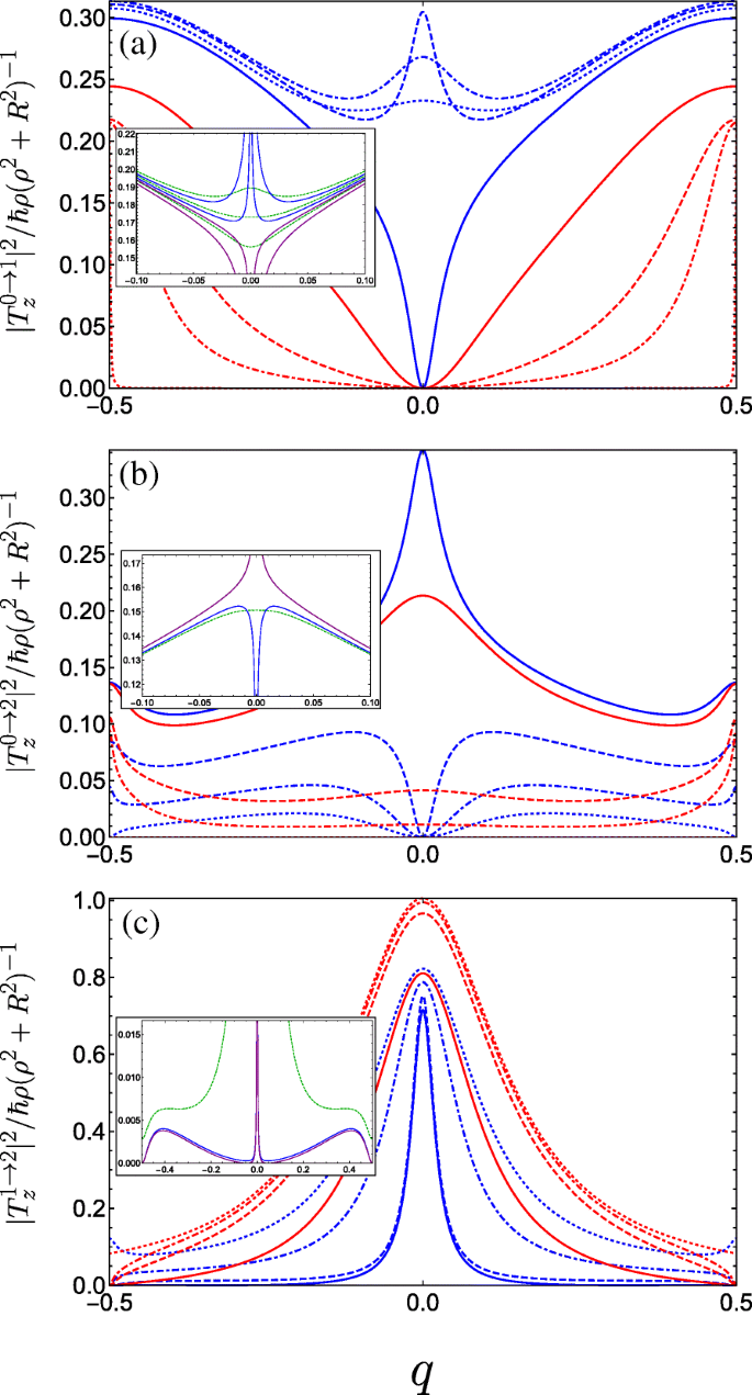
Square of the dimensionless momentum operator matrix element between the g th and f th subbands in the first Brillouin zone as a function of the dimensionless wave vector q of the electrons photoexcited by linearly z -polarized radiation and for a variety of parameter combinations spanning the first incident of resonance. The different blue curves keep A g =0.5 and C ⊥ =0 fixed and vary B g =0.1, 0.2, and 0.3 corresponding to dot-dashed, dashed, and solid. The different red curves keep B g =0.3 and C ⊥ =0 fixed while varying A g =0.05, 0.1 and 0.3 as dot-dashed, dashed, and solid, while the dotted blue (dotted red) plots the limiting case A g =0.5 &B g →0 (A g →0 &B g =0.3). un Transitions between the ground and first bands. The inset plots the behaviour for fixed A g =0.5 and changing B g crossing the resonant condition at B g =0.25 (see text) in a reduced q -range, ranging from upper blue B g =0.245, lower blue B g =0.249, upper purple B g =0.251, to lower purple B g =0.255. The dashed green curves are for small non-zero transverse field C ⊥ =0.05 ranging from B g =0.245 (upper curve) to B g =0.255 (lower curve) in increments of 0.05. b Plots transitions between the ground and second bands, the inset plots the behaviour close to resonance when A g =0.5; blue is B g =0.249, purple is B g =0.251, and dark green is at resonance with C ⊥ =0.05. c Plots transitions between the first and second bands, the parameters for the inset are the same as those in (b )
In Fig. 6, we plot the absolute square of the momentum operator matrix element for right-handed circularly polarized light which propagates along the helix axis, given by |T x +iT y | 2 . Notably, we observe a large anisotropy between the two halves of the first Brillouin zone, while the result for left-handed polarization is a mirror image to what we see in Fig. 6. Physically, this can be attributed to the conversion of the photon angular momenta to the translational motion of the free charge carriers projected onto the direction of the helix axis, with an unequal population of the excited subband in a preferential momentum direction controlled by the relative handedness of both the helix and the circular polarization of light. An intuitive mechanical analogue would be the rotary motion of Archimedes’ screw being converted into the linear motion of water along the direction of the screw axis dictated by the handedness of the thread. As such, our system of a double-gated nanohelix irradiated by circularly polarized light exhibits a photogalvanic effect, whereby one can choose the net direction of current by irradiating with either right- or left-handed circularly polarized light [44, 45, 89]. This differs from conventional one-dimensional superlattices, wherein the circular photogalvanic effect stems from the spin-orbit term appearing in the effective electron Hamiltonian and is consequently a weaker and hard-to-control phenomenon [90, 91]. The electric current induced by promoting electrons from the ground subband to an excited subband f via the absorption of circularly polarized light can be understood from the equation for the electric current contribution from the f th subband
$$ j_{f} =\frac{e}{2 \pi \rho} \int dq \left[ v_{f}(q) \tau_{f}(q) - v_{g}(q) \tau_{g} (q) \right] \Gamma_{CP}^{g \rightarrow f}(q), $$ (17)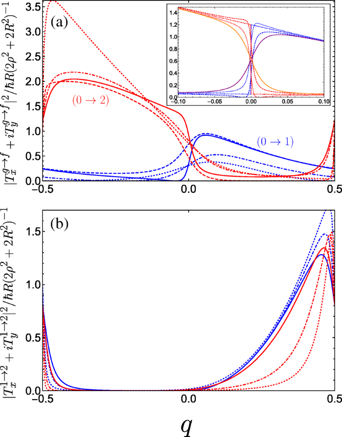
Square of the dimensionless momentum operator matrix element between the g th and f th subbands in the first Brillouin zone as a function of the dimensionless wave vector q of the electrons photoexcited by right-handed circularly polarized radiation |T x +iT y | 2 and for a variety of parameter combinations spanning the first incident of resonance. un The blue curves denote transitions between the ground and first band while the red curves denote transitions between the ground and second band, both with the following parameters:A g =0.5 and B g =0.3 for solid curves, A g =0.5 and B g =0.1 for dashed curves, A g =0.3 and B g =0.3 for dot-dashed curves, and A g =0.01 and B g =0.3 for dotted curves (as A g →0 the maximum of the 0→2 increases rapidly as it approaches q =− 1/2). The inset plots the behaviour as B g is tuned through resonance for A g =0.5; dotted is B g =0.24, dot-dashed is B g =0.25, and dashed is B g =0.26. The solid purple (orange) curve denotes transitions between the ground and first (second) band at resonance with C ⊥ =0.05 applied. b Plots transitions between the first and second bands. The different blue curves keep A g =0.5 fixed and vary B g =0, 0.2, and 0.3 corresponding to dotted, dot-dashed, and solid. The different red curves keep B g =0.3 fixed while varying A g =0.05, 0.1, and 0.3 as dotted, dot-dashed, and solid. We have omitted plots for C ⊥ ≠0 here as it yields no great qualitative change to the matrix elements
where \(v_{g,f}(q)=(\rho /\hbar)\partial \varepsilon _{g,f}/\partial q \) is the antisymmetric electron velocity v (q )=− v (− q ) (which we can deduce from the symmetric dispersion curves), τ g,f (q ) is a phenomenological relaxation time, and \(\Gamma _{CP}^{g \rightarrow f}(q)\) is the transition rate resulting from the optical perturbation of the electron system. Given that \(\Gamma _{CP}^{g \rightarrow f}(q) \propto |T_{x}^{g \rightarrow f} + i T_{y}^{g \rightarrow f}|^{2}\) for right-handed circularly polarized light where T x et T y are given by Eqs. 16a and 16b, respectively. The anisotropy present in Fig. 6a enters Eq. 17 to yield a non-zero photocurrent. This current flows in the opposite direction for left-handed polarization. Such a circular photogalvanic effect is also exhibited in chiral carbon nanotubes under circularly polarized irradiation [92, 93], although tunability predominantly stems from manipulating the nanotube physical parameters, which are hard to control. The double-gated nanohelix system offers superior versatility by fully controlling the landscape of the superlattice potential, which can be used to tailor the non-equilibrium asymmetric distribution function of photoexcited carriers (as shown in Fig. 6 for inter-subband transitions between the three lowest subbands).
On a side note, we expect that (as with chiral carbon nanotubes [93–95]) the application of a magnetic field along the nanohelix axis can take up the role played by circularly polarized radiation, whereby the current is induced by a magnetic-field-induced asymmetric energy dispersion—which in turn produces an anisotropic electron velocity distribution across the two halves of the Brillouin zone.
Conclusions
In summary, we have shown that the system of a nanohelix between two aligned gates modelled as charged wires is a tunable binary superlattice. The band structure for this system exhibits a diverse behaviour, in particular revealing energy band crossings accessible via tuning the voltages on the gates. The application of an electric field normal to the plane defined by the gates and the helix axis introduces an additional parameter with which to open a band gap at these crossings. Engineering the band structure in situ with the externally induced superlattice potential along a nanohelix provides a clear advantage over conventional heterostructure superlattices with a DQW basis [96, 97]. Both systems can be used as high-responsivity photodetectors, wherein tailoring the band structure (to the so-called band-aligned basis [98–100]) can lead to a reduction in the accompanying dark current. Here control over the global depth of the quantum wells also permits versatility over the detection regime, which can lie within the THz range. We have also investigated the corresponding behaviour of electric dipole transitions between the lowest three subbands induced by both linearly and circularly polarized light, which additionally allows this system to be used for polarization sensitive detection. Finally, the ability to tune the system such that a degenerate excited state is optically accessible from the ground state, along with the inherent chirality present in the light-matter interactions, may make this a promising system for future quantum information processing applications [101]. It is hoped that with the advent of sophisticated nano-fabrication capabilities [102], fully controllable binary superlattice properties will be realized in a nanohelix and will undoubtedly contribute to novel optoelectronic applications.
Appendix
Touching energy bands at Brillouin zone boundary when A g =C ⊥ =0
Here, we show using matrix algebra that in the picture of a binary superlattice pairs of subbands touch at the Brillouin zone edges if A g =C ⊥ =0 and B g ≠0, as seen from the solid blue curves in Fig. 3a. Equation 5 is equivalent to the following N -by-N pentadiagonal matrix Hamiltonian with zeros on the leading sub- and superdiagonals:
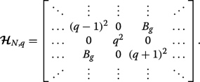 (18)
(18) Let us consider q =1/2 (we could alternatively take q =− 1/2) which makes the leading diagonal symmetric. We can then express this matrix Hamiltonian \(\widetilde {\mathcal {\boldsymbol {H}}}_{N} \equiv \boldsymbol {\mathcal {H}}_{N,q=1/2} \) in block form as
 (19)
(19) où
 (20)
(20) are both of dimension N /2-by- N /2, and J is the exchange matrix. We may construct a matrix via permuting \(\boldsymbol {\mathcal {H}}_{N}\) with the N -by-N permutation matrix \(\boldsymbol {\mathcal {P}}_{N}\),
$$ \boldsymbol{\mathcal{P}}_{N} =\left[ \begin{array}{cccccc} 1 &0 &\hdots &\hdots &\hdots &0 \\ 0 &\hdots &\hdots &\hdots &\hdots &1 \\ 0 &1 &\hdots &\hdots &\hdots &0 \\ 0 &\hdots &\hdots &\hdots &1 &0 \\ \vdots &&&&&\vdots \\ 0 &\hdots &\hdots &1 &\hdots &0 \\ \end{array} \right], $$ (21)such that the permutation-similar matrix is
 (22)
(22) Hence, the eigenvalues of \(\boldsymbol {\mathcal {P}}_{N}^{-1}\widetilde {\boldsymbol {\mathcal {H}}}_{N} \boldsymbol {\mathcal {P}}_{N}\), which are the same as the eigenvalues \(\widetilde {\boldsymbol {\mathcal {H}}}_{N}\), are double degenerate with the values given by the eigenvalue spectrum of the tridiagonal matrix C
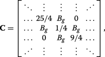 (23)
(23) which can also be expressed succinctly in terms of the previously defined matrices via \(\mathbf {C}=\boldsymbol {\mathcal {P}}_{N/2}^{-1}\mathbf {A}\boldsymbol {\mathcal {P}}_{N/2}+\boldsymbol {\mathcal {P}}_{N/2}^{-1}\mathbf {B}\mathbf {J}\boldsymbol {\mathcal {P}}_{N/2}^{4}\). We can see that applying C ⊥ ≠0 (inset of Fig. 3a) or both C ⊥ et A g ≠0 (inset of Fig. 3b) ruins the symmetry in the matrix Hamiltonian and prevents the existence of eigenvalues with multiplicity beyond unity, resulting in the appearance of band gaps.
Energy crossing at centre of Brillouin zone between third and forth subbands
As an example, let us specifically consider the case where p =2, wherein the matrices (12) and (13) become:
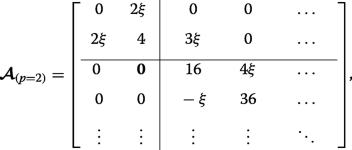 (24)
(24) and
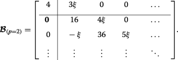 (25)
(25) This case corresponds to the crossings of the blue curves at the edge of the Brillouin zone in Fig. 3d (whereas p =0 results in crossings at q =0 in Fig. 3b). The lower eigenvalues are found exactly by diagonalizing each of the two finite matrices and they interlace, yielding \(\eta _{0,1,2} =2-\sqrt {4+4\xi ^{2}}, 4, 2+\sqrt {4+4\xi ^{2}}\). The infinite lower-right-hand block tridiagonal matrices coincide, thus the remaining double degenerate eigenvalues are found by approximately or numerically solving Det[D −η I ]=0.
Disponibilité des données et des matériaux
The data for the figures all stem from numerically diagonalizing the matrix described by Eq. 5 and can readily be achieved in any numerical software package. With this in mind, the datasets used and/or analyzed during the current study are available from the corresponding author on reasonable request.
Nanomatériaux


