Mémoire résistive à accès aléatoire (RRAM) :une présentation des matériaux, du mécanisme de commutation, des performances, du stockage de cellules multiniveaux (mlc), de la modélisation et des applications
Résumé
Dans ce manuscrit, les progrès récents dans le domaine de la technologie de mémoire à accès aléatoire résistive (RRAM), qui est considérée comme l'une des technologies de mémoire émergentes les plus remarquables en raison de sa vitesse élevée, de son faible coût, de sa densité de stockage améliorée, de ses applications potentielles dans divers domaines et de son excellent l'évolutivité est examinée en détail. Tout d'abord, un bref aperçu du domaine des technologies de mémoire émergentes est fourni. Les propriétés des matériaux, le mécanisme de commutation de résistance et les caractéristiques électriques de la RRAM sont discutés. En outre, divers problèmes tels que l'endurance, la rétention, l'uniformité et l'effet de la température de fonctionnement et du bruit télégraphique aléatoire (RTN) sont élaborés. Une discussion sur la capacité de stockage de cellules multiniveaux (MLC) de la RRAM, qui est attrayante pour obtenir une densité de stockage accrue et un faible coût, est présentée. Différents schémas de fonctionnement pour obtenir un fonctionnement MLC fiable ainsi que leurs mécanismes physiques ont été fournis. En outre, une description détaillée des méthodologies de commutation et des relations de tension de courant pour divers modèles RRAM populaires est couverte dans ce travail. Les applications potentielles de la RRAM à divers domaines tels que la sécurité, l'informatique neuromorphique et les systèmes logiques non volatiles sont brièvement abordées. Le présent article de synthèse se termine par une discussion sur les défis et les perspectives d'avenir du RRAM.
Introduction
La mémoire vive appelée RAM peut être volatile ou non volatile. Une mémoire volatile perd ses données précédemment stockées lors de la suppression de l'alimentation, comme c'est le cas pour la mémoire vive dynamique (DRAM) et la mémoire vive statique (SRAM). Pour la mémoire non volatile, le contenu qui était stocké précédemment continuera d'être conservé même après la suppression de l'alimentation. La mémoire flash est un exemple typique de mémoire non volatile. Les technologies de mémoire combinent les avantages et les inconvénients pour obtenir des performances plus élevées, par ex. Les DRAM utilisées dans un système informatique ont une capacité et une densité élevées, mais elles sont volatiles, ce qui signifie qu'il est nécessaire de les actualiser toutes les quelques millisecondes. Du fait de ce rafraîchissement, la consommation énergétique du dispositif augmente ce qui n'est pas souhaitable. La SRAM, en revanche, est rapide mais elle est également volatile, tout comme la DRAM; de plus, les cellules SRAM sont de plus grande taille ce qui gêne sa mise en œuvre à grande échelle. La mémoire flash, qui se compose essentiellement d'un transistor à effet de champ métal-oxyde-semiconducteur (MOSFET) en plus d'une grille flottante dans chaque cellule de mémoire, est actuellement largement utilisée, en particulier pour les applications embarquées en raison de son faible coût et de sa haute densité. . Selon la façon dont les cellules de mémoire sont organisées, la mémoire Flash est classée en Flash NOR et Flash NAND [1]. Dans NOR Flash, les cellules sont lues et programmées individuellement car elles sont connectées en parallèle à des lignes de bits. Cela ressemble à la connexion en parallèle de transistors dans une architecture de porte CMOS NOR. Pour le cas de Flash NAND, l'architecture ressemble à celle d'une porte NAND CMOS car les cellules sont connectées en série aux lignes de bit. Il faut noter que moins d'espace est consommé par la connexion en série par rapport à la connexion en parallèle, ce qui se traduit par un coût réduit de Flash NAND. Cependant, les deux types de mémoires Flash souffrent de plusieurs inconvénients tels qu'une faible vitesse de fonctionnement (temps d'écriture/effacement :1 ms/0,1 ms), une endurance limitée (10 6 cycles d'écriture/effacement) et tension d'écriture élevée (> 10 V) [2].
Les technologies de mémoire mentionnées ci-dessus, c'est-à-dire DRAM, SRAM et Flash, sont des mémoires basées sur le stockage de charge. La DRAM stocke les informations sous forme de charge au niveau du condensateur et la SRAM est basée sur le stockage de charge aux nœuds des inverseurs à couplage croisé, tandis que la technologie de mémoire Flash utilise la grille flottante du transistor pour stocker la charge. Toutes ces technologies de mémoire basées sur le stockage de charge existantes sont actuellement confrontées à des défis pour passer à un nœud de 10 nm ou au-delà. Ceci est attribué à la perte de charge stockée à l'échelle nanométrique, ce qui entraîne une dégradation des performances, de la fiabilité et de la marge de bruit. De plus, les exigences de puissance dynamique de rafraîchissement élevée pour la DRAM et de puissance de fuite à la fois pour la SRAM et la DRAM posent de sérieux défis pour la conception de la future hiérarchie de mémoire.
Par conséquent, une nouvelle classe de mémoires généralement appelée technologies de mémoire émergentes est actuellement en cours de développement et fait l'objet de recherches actives principalement dans l'industrie dans le but de révolutionner la hiérarchie de mémoire existante [3]. Ces technologies de mémoire émergentes visent à intégrer la vitesse de commutation de la SRAM, une densité de stockage comparable à celle de la DRAM et la non-volatilité de la mémoire Flash, devenant ainsi des alternatives très intéressantes pour la future hiérarchie de mémoire.
Pour classer un périphérique de mémoire comme un périphérique idéal, il doit avoir les caractéristiques suivantes :faible tension de fonctionnement (<1 V), longue endurance en cyclage (>10 17 cycles), durée de conservation des données améliorée (>10 ans), faible consommation d'énergie (fJ/bit) et évolutivité supérieure (<10 nm) [4]. Cependant, aucun souvenir à ce jour ne satisfait à ces caractéristiques idéales. Diverses technologies de mémoire émergentes sont activement étudiées pour répondre à une partie de ces caractéristiques de mémoire idéales. Ces technologies de mémoire qui dépendent du changement de résistance plutôt que de la charge pour stocker les informations sont les suivantes :(i) mémoire à changement de phase (PCM), (ii) mémoire à accès aléatoire magnétorésistive à couple de transfert de spin (STT-MRAM) et ( iii) mémoire vive résistive (RRAM). Dans la mémoire à changement de phase, le milieu de commutation est constitué d'un matériau chalcogénure (généralement Ge2 -Sb2 -Te5 , TPS) [5–7]. Le PCM repose sur la différence de résistance entre la phase cristalline et la phase amorphe pour une capacité de stockage de données efficace. La phase cristalline désigne l'état à faible résistance (LRS) ou l'état ON du dispositif tandis que la phase amorphe désigne l'état à haute résistance (HRS) ou l'état OFF. L'opération SET correspond à LRS généralement appelé stockage de la valeur logique « 1 », tandis que l'opération RESET correspond à HRS stockant la valeur logique « 0 » dans l'appareil. Pour le fonctionnement SET, le PCM est chauffé au-dessus de sa température de cristallisation lors de l'application d'une impulsion de tension, tandis que pour le fonctionnement RESET, un courant électrique plus important traverse la cellule puis est brusquement coupé afin de fondre puis de tremper le matériau afin de atteindre l'état amorphe.
Dans la mémoire vive magnétorésistive à couple de transfert de spin, la capacité de stockage est due à la jonction tunnel magnétique (MJT) [8-10], qui se compose de deux couches ferromagnétiques et d'un diélectrique à effet tunnel pris en sandwich entre elles. La direction magnétique de la couche de référence est fixe, tandis que l'application d'un champ électromagnétique externe peut modifier la direction magnétique de la couche ferromagnétique libre. Si la couche de référence et la couche libre ont la même direction d'aimantation, le MTJ est appelé dans le LRS. Pour MTJ, pour être dans le HRS, le sens de l'aimantation des deux couches ferromagnétiques est anti-parallèle. La RRAM est constituée d'une couche isolante (I) prise en sandwich entre les deux électrodes métalliques (M) [11, 12]. La RRAM repose sur la formation et la rupture de filaments conducteurs correspondant respectivement à LRS et HRS, dans l'isolant entre deux électrodes [13-15].
Une comparaison détaillée des technologies de mémoire existantes et émergentes est présentée dans le tableau 1. Comme le montre le tableau, les STT-MRAM et PCM présentent les avantages d'une zone plus petite par rapport à celle de la SRAM. Alors que STT-MRAM offre une vitesse d'écriture/lecture rapide, une longue endurance et une faible tension de programmation, d'un autre côté, le PCM présente l'inconvénient d'une latence d'écriture étendue. La RRAM a une tension de programmation inférieure et une vitesse d'écriture/lecture plus rapide par rapport à Flash et est considérée comme un remplacement potentiel de la mémoire Flash. Parmi tous les candidats à la technologie de mémoire émergente, la RRAM présente des avantages significatifs tels qu'une fabrication facile, une structure métal-isolant-métal (MIM) simple, une excellente évolutivité, une vitesse de la nanoseconde, une longue conservation des données et la compatibilité avec la technologie CMOS actuelle, offrant ainsi un solution à la future mémoire numérique [16]. Les avantages les plus significatifs de la RRAM sont illustrés à la Fig. 1.
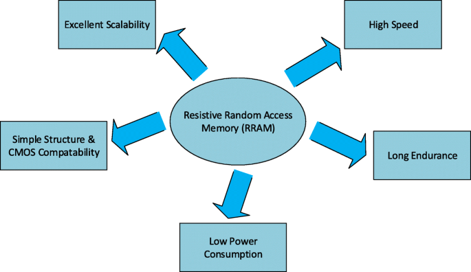
Avantages de la RRAM
Dans ce travail, les progrès récents et un aperçu détaillé de la technologie RRAM sont présentés. Un examen des matériaux de commutation ainsi que la classification des modes de commutation et les détails du mécanisme de commutation sont abordés dans la section « Mémoire résistive à accès aléatoire (RRAM) ». La section « Metriques de performance de la mémoire à accès aléatoire résistif (RRAM) » met en évidence diverses métriques de performance de la RRAM. Les caractéristiques des cellules à plusieurs niveaux (MLC) de la RRAM ainsi que divers schémas de fonctionnement MLC et leurs mécanismes physiques sont analysés dans la section « Mémoire à accès aléatoire résistif à plusieurs niveaux (RRAM) ». Une discussion détaillée sur la modélisation du périphérique RRAM est présentée dans la section « Modélisation des périphériques RRAM ». Dans la section « Applications de la RRAM », diverses applications de la RRAM sont discutées. Enfin, les défis et perspectives d'avenir du RRAM sont présentés dans la section « Défis et perspectives d'avenir ». La répartition par catégorie des articles consultés dans la préparation de ce manuscrit de revue est présentée dans la figure 2.
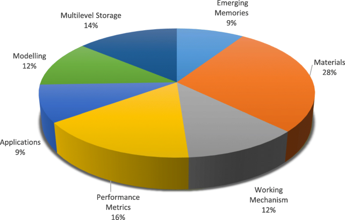
Distribution par catégorie des articles consultés pour la préparation de l'examen sur RRAM
Mémoire résistive à accès aléatoire (RRAM)
Matériaux de commutation de résistance
Il a été observé que dans certains isolants, le changement de résistance se produit sous l'application du champ électrique appliqué. Cette propriété de changement de résistance a récemment été étudiée pour développer de futures mémoires non volatiles [17]. Le phénomène de commutation de résistance a été observé dans une variété d'oxydes, mais les oxydes métalliques binaires ont été largement étudiés en tant que matériau de commutation préféré pour les futures applications de mémoire non volatile, principalement en raison de leur compatibilité avec le traitement CMOS BEOL. Divers matériaux à base d'oxyde métallique présentant la commutation de résistance non volatile tels que l'oxyde d'hafnium (HfO x ) [18–23], oxyde de titane (TiO x ) [24–31], oxyde de tantale (TaO x ) [32–36], oxyde de nickel (NiO) [37–40], oxyde de zinc (ZnO) [41–46], titanate de zinc (Zn2 TiO4 ) [47], oxyde de manganèse (MnO x ) [48, 49], oxyde de magnésium (MgO) [50], oxyde d'aluminium (AlO x ) [51–53], et le dioxyde de zirconium (ZrO2 ) [54-58] ont attiré le plus d'attention et ont été largement étudiés au cours des dernières années. Ces oxydes métalliques sont généralement déposés par dépôt laser pulsé (PLD), dépôt de couche atomique (ALD) et pulvérisation cathodique réactive. Cependant, l'ALD est une méthode largement préférée en raison de sa capacité à contrôler avec précision l'épaisseur et l'uniformité du film mince [59].
Dans les dispositifs électroniques conventionnels, le choix du matériau des électrodes est important car ils servent de chemins de transport pour les porteurs. Pour la RRAM, le choix du matériau de l'électrode affecte grandement le comportement de commutation de l'appareil. Par exemple, dans la structure cuivre/poly(3-hexylthiophène) :[6,6]-phényl-C61-butyrique acide méthylique/indium-oxyde d'étain (Cu/P3HT :PCBM/ITO), un comportement de commutation résistif stable a été observé; cependant, il a disparu après le remplacement de l'électrode en Cu par l'électrode en Pt [60]. Une grande variété de matériaux ont été utilisés comme électrodes pour la RRAM. Les matériaux d'électrode peuvent être regroupés en cinq catégories sur la base de leur composition, y compris les électrodes de substance élémentaire, les électrodes à base de silicium, les électrodes d'alliage, les électrodes d'oxyde et les électrodes à base de nitrite. Les électrodes les plus abondantes et les plus couramment utilisées sont les électrodes de substances élémentaires qui incluent Al [51], Ti[49], Cu[30], graphène [61], nanotubes de carbone [62], Ag [41], W [36], et Pt [44]. Pour les électrodes à base de silicium, le Si de type p et le Si de type n [63] sont les seuls types d'électrodes utilisés. Les électrodes en alliage stabilisent généralement le comportement de commutation résistive et comprennent principalement Cu-Ti [64], Cu-Te [65] et Pt-Al [66]. Les électrodes à base de nitrure les plus courantes sont le TiN et le TaN [67, 68]. Les électrodes à base d'oxyde sont relativement abondantes, y compris le ZnO dopé à l'Al [69], le ZnO dopé au Ga [70] et l'ITO [71].
La liste des matériaux d'oxyde métallique qui ont été utilisés récemment dans la fabrication du dispositif RRAM ainsi que diverses combinaisons de matériaux utilisés pour l'électrode supérieure et l'électrode inférieure sont présentées dans le tableau 2. Une comparaison détaillée des différents paramètres est également présentée. De la grande variété de matériaux utilisés, on peut prédire que la commutation de résistance non volatile est largement observée dans divers types d'oxydes. Le choix du matériau pour la fabrication de la RRAM lui donne un avantage, car les structures en oxyde métallique (MOM) peuvent être facilement fabriquées en utilisant les oxydes actuellement utilisés dans la technologie des semi-conducteurs. Le matériau de l'électrode inférieure dans la RRAM est généralement du platine, qui est un peu difficile à graver. Pour la structure d'un seul appareil, la RRAM peut partager la même électrode inférieure alors que, pour l'architecture crossbar, les électrodes inférieures séparées sont utilisées pour chaque appareil. Ils peuvent être obtenus successivement par dépôt physique en phase vapeur et par décollage. L'électrode supérieure et la couche de commutation résistive sont déposées soit par dépôt de couche atomique (ALD) soit par dépôt physique en phase vapeur (PVD).
Modes de commutation de résistance
Une mémoire résistive à accès aléatoire (RRAM) consiste en une cellule de mémoire à commutation résistive ayant une structure métal-isolant-métal généralement appelée structure MIM. La structure comprend une couche isolante (I) prise en sandwich entre les deux électrodes métalliques (M). Le schéma et la vue en coupe d'une cellule RRAM sont illustrés respectivement aux figures 3a et b.
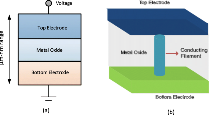
un Schéma de la structure métal-isolant-métal pour RRAM. b Vue en coupe de la RRAM
L'application de l'impulsion de tension externe à travers la cellule RRAM permet une transition de l'appareil d'un état à haute résistance (HRS), ou état OFF généralement appelé valeur logique '0' à un état à faible résistance (LRS), ou état ON généralement appelée valeur logique « 1 » et vice versa. Le phénomène de commutation résistive (RS) est considéré comme la raison de ce changement de valeurs de résistance dans une cellule RRAM. Une RRAM telle que préparée est initialement dans l'état de haute résistance (HRS), pour basculer le dispositif du HRS vers le LRS, l'application de l'impulsion haute tension permet la formation de chemins conducteurs dans la couche de commutation et la cellule RRAM est commutée dans un LRS [72]. Ce processus qui se produit en raison de la rupture douce de la structure métallique isolante (MIM) est généralement appelé «électroformage» et la tension à laquelle ce processus se produit est appelée tension de formation (V f ). Il faut noter que la tension de formation dépend de la surface de la cellule [73] et de l'épaisseur de l'oxyde [74]. Maintenant, pour passer la cellule RRAM du LRS au HRS, l'impulsion de tension appelée tension RESET (V réinitialiser ) est appliqué, ce qui permet cette transition de commutation et le processus est appelé processus « RESET » [75-78]. Le HRS de la RRAM peut être changé en LRS lors de l'application de l'impulsion de tension. La tension à laquelle se produit la transition de HRS à LRS est appelée tension SET (V définir ) et le processus est appelé processus « SET » [79]. Pour lire efficacement les données de la cellule RRAM, une petite tension de lecture qui ne perturbera pas l'état actuel de la cellule est appliquée pour déterminer si la cellule est dans l'état logique 0 (HRS) ou l'état logique 1 (LRS). Étant donné que LRS et HRS conservent leurs valeurs respectives même après la suppression de la tension appliquée, la RRAM est une mémoire non volatile. Selon la polarité de la tension appliquée, la RRAM peut être classée en deux types de modes de commutation :(i) commutation unipolaire et (ii) commutation bipolaire [80]. Dans la commutation unipolaire, la commutation (processus de réglage et de réinitialisation) de l'appareil entre divers états de résistance ne dépend pas de la polarité de la tension appliquée, c'est-à-dire que la commutation peut se produire en appliquant une tension de même polarité mais de magnitude différente, comme illustré à la Fig. 4a. Dans la commutation bipolaire, d'autre part, la commutation (processus de réglage et de réinitialisation) de l'appareil entre divers états de résistance dépend de la polarité de la tension appliquée, c'est-à-dire une transition d'un HRS à LRS, se produit à une polarité (soit positive soit négatif) et la polarité opposée bascule la cellule RRAM dans le HRS comme illustré sur la figure 4b. Dans la commutation unipolaire, l'échauffement Joule est interprété comme le mécanisme physique responsable de la rupture d'un filament conducteur lors de l'opération de réinitialisation. Dans la commutation bipolaire, en revanche, la migration des espèces chargées est la principale force motrice de la dissolution des filaments conducteurs, bien que le chauffage Joule contribue toujours à accélérer la migration. Afin de s'assurer qu'il n'y a pas de rupture permanente de la couche de commutation diélectrique pendant le processus de formation/mise en place de la RRAM, un courant de conformité (I cc ) est appliqué pour le périphérique RRAM. Le courant de conformité (I cc ) est généralement assurée par un dispositif de sélection de cellule (transistor, diode, résistance) ou par un analyseur de paramètres à semi-conducteurs lors du test hors puce.
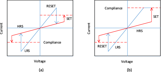
Courbes I-V pour RRAM. un Commutation unipolaire et b commutation bipolaire [4]
Mécanisme de commutation résistif
La commutation de la cellule RRAM est basée sur la croissance du filament conducteur (CF) à l'intérieur d'un diélectrique. Le CF est un canal de diamètre très inférieur de l'ordre du nanomètre qui relie les électrodes supérieure et inférieure de la cellule mémoire. Un état de faible résistance (LRS) avec une conductivité élevée est obtenu lorsque le filament est connecté et la résistance élevée (HRS) se produit lorsque le filament est déconnecté avec un espace entre les électrodes [91]. Sur la base de la composition du filament conducteur, la RRAM peut être classée dans les deux types suivants :(i) la RRAM à base d'ions métalliques également appelée mémoire à accès aléatoire à pont conducteur (CBRAM) et (ii) la RRAM à base de filament à vide d'oxygène désignée sous le nom de « OxRRAM ». Il convient de noter ici que la CBRAM est parfois appelée mémoire de métallisation électrochimique (ECM), tandis que « OxRRAM » est parfois également appelée mémoire de changement de valence (VCM).
Dans la RRAM à base d'ions métalliques, également appelée « CBRAM », le mécanisme physique responsable de la commutation résistive est basé sur la migration des ions métalliques et les réactions de réduction/oxydation (redox) qui en découlent [92, 93]. La structure CBRAM consiste en une électrode supérieure oxydable (anode) telle que Ag, Cu et Ni, une électrode inférieure relativement inerte (cathode), par ex. W, Pt et une couche d'oxyde métallique prise en sandwich entre les deux électrodes. La formation de filaments dans de telles cellules mémoire se produit en raison de la dissolution des électrodes métalliques actives (le plus souvent Ag ou Cu), du transport de cations (Cu + ou Ag + ), et leur dépôt ou réduction ultérieur au niveau de l'électrode inférieure inerte [94]. Ainsi, le comportement de commutation résistive de ce type de RRAM est dominé par la formation et la dissolution des filaments métalliques.
Pour mieux comprendre le mécanisme de commutation de la CBRAM à base d'ions métalliques, considérons un exemple de cellules RRAM Ag/a-ZnO/Pt [41]. Une illustration schématique générale décrivant le processus de commutation d'une cellule de mémoire vive à pont conducteur est représentée sur la figure 5. L'état vierge de la cellule de mémoire CBRAM est représenté sur la figure 5a. L'électrode supérieure en Ag (TE) est un composant actif dans la formation du filament tandis que l'électrode inférieure en Pt est inerte. Lors de l'application de la polarisation de tension positive à l'électrode supérieure Ag, l'oxydation (Ag → Ag + + e − ) se produit à l'électrode supérieure à cause de laquelle Ag + des cations sont générés et se déposent dans la couche diélectrique (a-ZnO) à partir de l'électrode Ag. La polarisation négative sur l'électrode inférieure Pt (BE) attire l'Ag + cations, et à ce titre, la réaction de réduction (Ag + + e − → Ag) se produit à l'électrode inférieure. Ainsi, l'Ag + les cations sont réduits en atomes Ag et s'accumulent jusqu'à ce que le pont conducteur soit formé (Fig. 5b–d) et que le dispositif RRAM présente un LRS. Ce processus est appelé « SET ». Lorsque la polarité de la tension appliquée est inversée, le filament hautement conducteur se dissout presque complètement et l'appareil est dit dans l'état de haute résistance (HRS). Ce processus est appelé « RESET » et est illustré à la figure 5e.
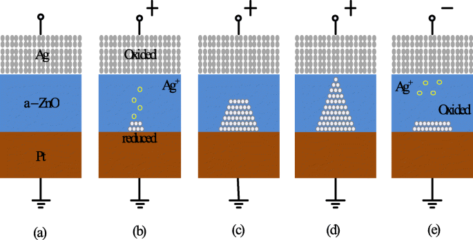
Schéma du mécanisme de commutation du pont conducteur RRAM. un État vierge du périphérique RRAM. b , c Oxydation de l'Ag et migration de l'Ag + cations vers la cathode et leur réduction. d L'accumulation d'atomes d'Ag et d'électrode de Pt conduit à la croissance d'un filament hautement conducteur. e La dissolution du filament a lieu lors de l'application d'une tension de polarité opposée [41]
Dans la RRAM basée sur les lacunes d'oxygène (OxRRAM), le mécanisme physique responsable de la commutation résistive est généralement associé à la génération de lacunes d'oxygène (V \(_{o}^{2+}\)) et le déplacement ultérieur des ions oxygène (O 2− ), permettant ainsi la formation de filament conducteur entre les électrodes supérieure et inférieure de la cellule RRAM [59]. Initialement, pour la cellule RRAM telle que fabriquée, le processus de formation, c'est-à-dire la rupture douce du diélectrique est essentiel. Une fois que la rupture diélectrique douce se produit, les atomes d'oxygène sont éliminés du réseau lors de l'application d'un champ électrique élevé vers l'interface anodique et deviennent des ions oxygène (O 2− ) alors que les lacunes en oxygène (V \(_{o}^{2+}\)) restent dans la couche d'oxyde. Les ions oxygène (O 2− ) réagissent avec les matériaux d'anode ou sont déchargés sous forme d'oxygène neutre sans réseau, si les métaux nobles sont utilisés comme matériaux d'anode pour former une couche d'oxyde interfaciale. Ainsi, l'interface électrode/oxyde se comporte comme un « réservoir d'oxygène » [85]. Ensuite, l'accumulation des lacunes en oxygène (V \(_{o}^{2+}\)) dans l'oxyde en vrac fait passer la cellule RRAM à l'état de faible résistance (LRS) à mesure que le filament conducteur (CF) se forme et que le courant appréciable circule dans le dispositif. Pour remettre l'appareil en état de haute résistance (HRS), le processus de réinitialisation se produit au cours duquel les ions oxygène (O 2− ) migrer vers l'oxyde en vrac de l'interface anodique et soit se combiner avec les lacunes d'oxygène (V \(_{o}^{2+}\)) ou pour oxyder les précipités de CF métalliques et ainsi rompre partiellement le filament, rebasculant ainsi la cellule RRAM en HRS. Pour les cellules RRAM présentant un mécanisme de commutation unipolaire, la diffusion des ions oxygène (O 2− ) est activé thermiquement par le courant de chauffage Joule et en tant que tel, les ions oxygène diffusent depuis l'interface ou la région autour du CF en raison du gradient de concentration. En outre, il faut noter qu'un courant de réinitialisation relativement plus élevé est requis dans la RRAM de commutation unipolaire pour augmenter la température locale autour de CF. En revanche, dans la RRAM à commutation bipolaire, les ions oxygène (O 2− ) doit être aidée par le champ électrique inverse car la couche interfaciale peut présenter une barrière de diffusion importante et la diffusion thermique pure n'est pas suffisante. Il faut noter que la rupture partielle de CF a lieu dans les deux cas, faisant passer la cellule RRAM dans l'état de haute résistance (HRS). Ceci est principalement dû à la formation de lacunes d'oxygène (V \(_{o}^{2+}\)) et une région pauvre résultant en un trou tunnel pour les électrons. Pour remettre l'appareil au LRS (processus SET), le CF reconnecte les électrodes à la suite de la rupture douce dans la région de l'espace. Un processus de réglage/réinitialisation similaire peut se répéter pendant plusieurs cycles.
Sur la base de la discussion ci-dessus, la CBRAM, également connue sous le nom de mémoire de métallisation électrochimique (ECM), repose sur une électrode métallique électrochimiquement active telle que Ag, Cu ou Ni pour former une CF à base de cations métalliques [95]. Le CF dans les lacunes d'oxygène RRAM à base de filaments « OxRRAM », également connu sous le nom de mémoire de changement de valence (VCM) est composé de défauts de lacunes d'oxygène, au lieu d'atomes métalliques, en raison de la migration d'anions dans le matériau de stockage lui-même [96]. Bien que le mécanisme de commutation de « OxRRAM » et de « CBRAM » soit discuté en détail, il existe encore un débat sur les mécanismes de commutation des deux types de RRAM [97]. Par exemple, où le CF commence à se développer dans le processus défini et où s'arrêter dans le processus de réinitialisation, et comment ces lacunes d'oxygène/atomes de métal se rassemblent pour former le CF. Les caractéristiques courant-tension (I-V) de 20 cycles de commutation consécutifs de Ta/TaO x La structure RRAM basée sur /Pt [98] a été étudiée et la variation claire du LRS et du HRS pour des cycles de commutation consécutifs a été observée. En conséquence, la fenêtre de mémoire globale diminue, dégradant les performances globales de la RRAM. Cette variabilité de la résistance d'un cycle à l'autre est principalement attribuée à la formation aléatoire de CF ainsi qu'à sa rupture pendant l'opération de réglage et de réinitialisation respectivement.
Une comparaison de l'OxRRAM avec la CBRAM sur la base de divers paramètres opérationnels est présentée dans le tableau 3 [81, 84, 86-88, 99, 100]. Cette comparaison révèle la différence frappante en termes de caractéristiques d'endurance de ces types de mémoire RRAM. Cette dissemblance est due au fait que les filaments conducteurs de la CBRAM sont composés principalement d'atomes métalliques qui sont relativement plus faciles à dériver et à diffuser par rapport aux lacunes d'oxygène, provoquant ainsi la dégradation du temps de rétention et des caractéristiques d'endurance de la CBRAM par rapport à l'OxRRAM. Bien que le mécanisme de commutation des deux types de RRAM soit différent, il existe de nombreuses caractéristiques communes entre les deux. La seule différence significative est que l'endurance pour OxRRAM est significativement plus élevée que pour CBRAM.
Metriques de performance de la mémoire résistive à accès aléatoire (RRAM)
Endurance
La mémoire vive résistive implique des transitions fréquentes entre un état à haute résistance (HRS) et un état à faible résistance (LRS). Chaque événement de commutation entre les états résistifs peut introduire des dommages permanents et entraîner une dégradation des performances de la RRAM. L'endurance est ainsi définie comme le nombre de fois qu'un périphérique RRAM peut être commuté entre le HRS et le LRS tout en assurant un rapport fiable entre eux [101]. Ainsi, un test d'endurance détermine le nombre maximum de cycles de réglage/réinitialisation qui peuvent être commutés efficacement avant que le HRS et le LRS ne soient plus distinguables. Les caractéristiques d'endurance de la RRAM sont obtenues en effectuant une séquence de balayages I-V dans une cellule de commutation résistive et l'extraction ultérieure de R HRS et R LRS sur l'application d'une tension de lecture (typiquement 0,1 V) [41]. Cette méthode est fiable car on peut obtenir la commutation correcte de l'appareil à chaque cycle; cependant, cette méthode est très lente car le temps requis pour obtenir un balayage I-V peut être très élevé, en particulier si des courants plus faibles sont impliqués.
Les cycles d'endurance dans un H f O x La cellule RRAM montre une forte dépendance vis-à-vis de la taille de cellule, comme le montre la figure 6a, où une meilleure endurance dans un dispositif RRAM avec une plus grande taille de cellule est rapportée. De plus, la réduction verticale de l'épaisseur de la couche entraîne une dégradation des performances d'endurance pour la tension SET à 2,5 V, comme le montre la figure 6b [102]. Cette dégradation des performances d'endurance avec la réduction d'échelle de la couche de commutation est le résultat du nombre réduit d'ions dans la région active. H f O x -base RRAM présente une excellente performance d'endurance de 10 6 cycles sur une matrice de 1 ko avec une taille de cellule de 30 nm inférieure à 0,18 μ m et la même chose est illustrée à la Fig. 6c [103]. En ajoutant une couche supplémentaire de A l O x au-dessus de l'électrode inférieure (BE), la stabilité du réseau peut être encore améliorée à mesure que l'immunité aux perturbations de lecture pour HRS est augmentée. Pour T un O x -basé sur RRAM, une dégradation des performances d'endurance avec l'augmentation de la largeur d'impulsion et de l'amplitude de la tension RESET a été observée dans Ta/Ta2 O5 /TiN structure RRAM [105]. Une comparaison de l'électrode inférieure TiN et Ru dans le Ta/Ta2 O5 /TiN RRAM montre que la principale cause de dégradation de l'endurance est due à la réaction des ions oxygène avec l'électrode TiN. De plus, une endurance améliorée de 10 9 cycles de commutation a été obtenu sans vérification dans une structure RRAM similaire en réduisant le Ta2 O5 couche jusqu'à 3 nm [106] et utilisation d'impulsions triangulaires d'une largeur <5 ns. Pour les performances des baies à grande échelle, une comparaison de 2 Mo Ta2 O5 mémoire avant et après 10 5 cycles d'essai d'endurance est illustré à la Fig. 6d [104]. Les distributions de courant cellulaire montrent une petite variation pour les cycles initiaux et finaux. De plus, le courant de cellule pour le LRS tombe en dessous de 50 μ A, indiquant une faible consommation d'énergie de la baie. The resistive switching devices with endurance higher than 10 12 cycles have been reported in different types of RRAM cells involving tantalum oxide (TaO x )-based switching mediums [32, 36, 59]. Thus, tantalum oxide-based RRAM devices seem to be exhibiting the highest endurance.
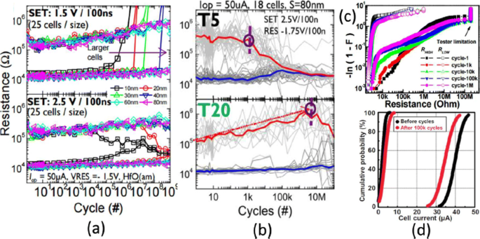
un Endurance cycles of H f O x -based RRAM at different SET voltage and cell size b with different thickness (T5=2 nm, T20=10 nm) at 2.5 V set voltage. c Resistance distribution of 1-kb array obtained from Weibull plots under different endurance cycles. d 100 k cycles endurance of 2-Mb-Ta2 O5 -based array; Reprinted from refs [102–104]
Retention
The data retention of a RRAM device involves investigating stability over a period of time for both LRS and HRS after undergoing set and reset transitions. In other words, the time period for which a memory cell will remain in a particular state after the set/reset operation determines the capability of a memory cell to retain its content [11]. The application of the constant voltage stress (CVS) over time using a low read voltage (0.1 V) and the measurement of the current versus time (I-t) curve for both LRS as well as the HRS enables the measurement of state retention. Due to the dispersing nature of atomic rearrangements induced in RRAM because of set voltage, the long retention time in LRS is difficult to obtain whereas, in HRS, retention is not a concern as it is usually the natural state of the device and RRAM will continue to remain in this state if no bias (or low bias) is applied. The retention in the LRS depends on the compliance limit during the SET transition, e.g. in RRAMs based on conductive filament switching mechanism, the larger compliance current produces a stronger conducting filament which is more stable over time [28, 41], as compared to a smaller compliance current. A projected endurance of 10 years at 85 ∘ C has been demonstrated in Ti/HfO2 /TiN [18]. A commonly used method to obtain device endurance is by applying read pulse at high temperature after certain time intervals (e.g. every 1 s) and extrapolate the resistance to a 10-year period. Although this method is easy to implement, it has certain limitations primarily due to the read voltage stress applied to the cell. An alternative method is to change the temperature and record the time until the device fails. Activation energy is extracted by plotting the Arrhenius plot and extrapolate down to the operating temperature. However, the limitation of this method is that waiting is necessary until the failure occurs in the RRAM cell, and thus, this method is more time-consuming and expensive.
The device characteristics of H f O x -based RRAM [81, 103] developed at the Industrial Technology Research Institute, Taiwan, are demonstrated to further understand the working of RRAM device. The transmission electron microscopy (TEM) image of the TiN/Ti/ H f O x /TiN RRAM device with 30-nm cell size is shown in Fig. 7a. The device exhibits bipolar switching characteristics and the I-V curve obtained at 200 μ A set compliance current is shown in Fig. 7b. The device presents endurance of 10 6 switching cycles with the resistance on/off ratio greater than 100 at set/reset programming conditions of + 1.5 V/– 1.4 V pulse with 500 μ s pulse width and the same is depicted in Fig. 7c.
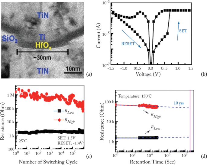
un Transmission electron microscopy (TEM) image of TiN/Ti/HfO x /TiN RRAM device. b Typical current-voltage (I-V) characteristics of the device with 30-nm cell size. c 10 6 endurance switching cycles obtained from 500 μ s pulse. d A retention lifetime of 10 years is expected by testing at 150 ∘ C; reprinted from refs. [81, 103]
Uniformity
In RRAM cell, poor uniformity of various device characteristics is one of the significant factors limiting the manufacturing on a wider scale. The switching voltages, as well as both the HRS and the LRS resistances, are among the parameters exhibiting a high degree of variation. The variations of the resistance switching include temporal fluctuations (cycle-to-cycle) and spatial fluctuations (device-to-device). The stochastic nature of the formation and rupture of conductive filament is believed to be the main reason for these variations. Cycle-to-cycle and device-to-device variability is a major hindrance for information storage in RRAM devices [59]. The observation of cycle-to-cycle variability is influenced by the change in the number of oxygen vacancy defects that arise in the CF due to its stochastic nature of formation and rupture during the switching event [107]. Due to this random nature of the CF, the prediction and the precise control of the shape of the CF becomes extremely challenging. This variability becomes worse as the compliance limit (i.e. compliance current ‘I cc ’) is reduced. On the other hand, for the higher value of ‘I cc ’, the ratio of standard deviation (σ ) and average resistance (μ ) is low, resulting in a smaller LRS resistance spread. This is attributed to the higher defects in the CF, thus forming a well-defined path for current conduction.
RRAM also exhibits device-to-device (cell-to-cell) non-uniformity which also degrades the memory performance by reducing the memory margin between two states. The origin of this variability is attributed to the non-uniformities in the fabrication process such as the thickness of the switching film, etching damages and surface roughness of the electrodes. A lot of research has been conducted to improve the uniformity of RRAM and several methods have been explored for the same. One of the methods utilizes the concept of inserting nano-crystal seeds which confine the paths of the conductive filament by enhancing the effect of local electric field [82, 90, 108]. In Ti/TiO 2−x /Au-based RRAM [28], the induction of platinum (Pt) nano-crystals within the thin TiO 2−x results in an enhanced uniformity of the RRAM cell. The Pt nano-crystals limit the switching effect into regions with high oxygen vacancy generation probability which results in improved uniformity. In another approach, engineering the electrode/oxide interface by embedding appropriate buffer layers is very useful in achieving uniform RRAM operation. In HfO x -based RRAM [109], a thin Al buffer layer is inserted between the TiN electrode and HfO x oxide layer. This results in significant improvement of set voltage distribution as well as the resistance distribution, thus enhancing the uniformity of the device. The improvement in the SET voltage and the resistance distribution of the RRAM device after inserting a thin Al buffer layer between TiN electrode and HfO x bulk oxide and the same is depicted in Fig. 8 [59]. Al atoms are assumed to diffuse into HfO2 thin films, and they tend to localize oxygen vacancies due to the reduced oxygen vacancy formation energy, thus stabilizing the generation of conductive filaments, which helps to improve the resistance switching uniformity.
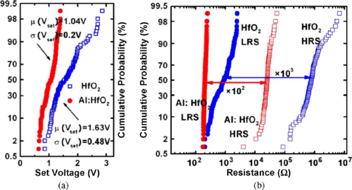
Uniformity improvement of Al buffered HfO x RRAM compared to HfO x -based RRAM array. un Statistical distribution of SET voltage (V set ) obtained from 100 DC sweep cycles. b HRS and LRS statistical distribution for 100 pulse sweep cycles; reprinted from ref. [59]
In addition to the materials engineering approach, a novel programming method has also been suggested to reduce fluctuations. A multistep forming technique was implemented in W/HfO2 /Zr/TiN [22]-based RRAM to minimize the overshoot current due to the parasitic effects. A multi-step forming technique results in the gradual formation of the filament; thus, a low set/reset current is achieved improving the switching characteristics of the device. Various other methods such as constant voltage forming and hot forming (usually referred to as forming at a higher temperature) have also been investigated to effectively reduce the resistance variations [110]. Another method of achieving high uniformity is by applying a pulse train rather than a single pulse to a RRAM cell [23]. This approach not only results in improved uniformity but also enhances the multilevel capability of a RRAM cell.
Effect of Operating Temperature and Random Telegraph Noise
To achieve a reliable performance of the RRAM device, the effect of operating temperature and random telegraph noise (RTN) is investigated. It is observed that the resistance of both the LRS and HRS states undergoes variations because of the change of operating temperature. The temperature study of TiN/HfO2 /Ti/TiN [111] was carried out. A positive sweep voltage of <3 V magnitude and compliance current of 1 μ A was applied for the electroforming. Once forming takes place, a reset voltage (V reset ) <–1 V switches the device back to the HRS (OFF state). To switch the device back to the LRS (ON state), set voltage (V set ) <1 V is applied.
The reset operation in RRAM device tends to show voltage-controlled negative differential resistance (NDR). The reset operation occurs abruptly at low temperatures, while for temperatures above room temperature, the reset process takes place more gradually. The resistance of the RRAM device in the pristine state, as well as the ON state and OFF state as a function of temperature is depicted in Fig. 9a. The semiconducting behavior is observed for the pristine state as well as the OFF state, i.e. resistance decreases with increase of temperature. For the ON state, a metallic characteristic is observed, i.e. resistance increases with increase of temperature. Due to the variation of resistance with change in temperature, R OFF /R ON also decreases from a value of 20 to approximately 5 over the temperature range of 213–413K. In Ti/HfO x /Pt devices, decrease in R OFF /R ON was observed with temperature-dependent cycling. This decrease in resistance ratio was attributed to the built-up of oxygen-vacancy-related traps inside the HfO2 metal oxide layer [112, 113]. Additionally, temperature-dependent measurements without set/reset operation were carried out to evaluate the impact of I-V cycling on the R OFF /R ON rapport. The sweep voltage across the RRAM device was stopped before reaching V set et V reset valeurs. For OFF state resistance (green rectangles), a weaker temperature dependence was observed in contrast to the ON state resistance (green circles) which exhibited similar characteristics, compared to the cycling case. From these observations, we infer that I-V cycling induces stronger temperature dependence, which decreases the R OFF /R ON rapport. The effect of temperature variation on the switching voltages V set et V reset is depicted in Fig. 9b. The slight variation in V set with changing temperature indicates that there is no significant temperature difference. For the case of V reset , the general trend is that a decrease in voltage value of about 0.2 V with temperature increase in the range of 233–333K is observed. Also, a slow increase of V reset is observed for 353–413K temperature range.
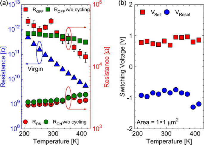
The effect of varying temperature on a virgin resistance (left axis) and the OFF-state as well as the ON-state resistances (right axis) at 213–413K temperature range and b switching voltages V set et V reset; reprinted from ref. [111]
Random telegraph noise (RTN) is another factor that affects the performance of RRAM. RTN has for long been used as an indicator of device performance and reliability. RTN decreases the memory margin between the HRS and LRS because of the extensive fluctuations in the read current during the read operation. Due to the effect of RTN, the read margin, scaling potential and the multilevel cell capability of a RRAM cell are greatly affected [114]; thus, it needs to be investigated to achieve reliable performance. To investigate the effect of bottom electrode on RTN, an analysis of Ta2 O5 /TiO2 RRAM [115] was carried out. The examples of complex RTN signals in LRS and HRS are depicted in Fig. 10. RTN causes read instability in the RRAM device, thus reducing the read margin, multibit storage implementation and hindering device scaling. The RTN is attributed to the trapping and de-trapping of electrons in the proximity of the CF in LRS whereas it occurs in the tunneling gap in the HRS state. Although the physics of RTN is still not clear and is being highly debated, the electron trapping and de-trapping which temporarily inhibits the charge transport is widely accepted as the mechanism responsible for fluctuation due to RTN. It is observed that with the decrease in operation current, the amplitude of RTN increases, thus highly affecting the HRS level. Therefore, it is necessary to ensure the additional resistance margin to achieve reliable performance. RTN in RRAM has been researched extensively, although the physical mechanism of RTN is still not explicitly defined. RTN can be utilized as a tool to map the movements of active vacancies in RRAM due to its time-dependent variation. This might be quite useful to understand the failure mechanisms of other reliability issues.
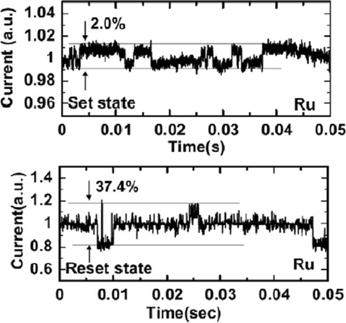
Complex RTN signals in LRS and HRS of Ta2 O5 /TiO2 -based RRAM depicting normalized noise amplitude and average current; reprinted from ref. [114]
Multilevel Resistive Random Access Memory (RRAM)
Multilevel Per Cell (mlc) Storage
Owing to their small physical size and low power consumption, RRAM devices are potential for future memory and logic applications. Increased storage density is among the most critical aspects of memory technology to enable the design of multibit capacity [89] memory cells. The multiple resistive states can be achieved in RRAM cells which provide benefits of low-cost and high-density non-volatile data storage solutions. Currently, a lot of research is being conducted in the area of RRAM to scale down the dimensions and increase the structural density of memory arrays. Previously, the storage density of RRAM has been increased by the reduction of device size; however, the complexity involved in the experimental procedures limits its successful implementation. Another suggested method is employing three-dimensional (3D) crossbar architectures. Two types of architectures of ‘vertical’ and ‘crossbar RRAM’ have been proposed [116, 117]; however, both these architecture types require advanced fabrication procedures which is not desirable. A much simpler alternative to increase storage density in RRAM devices is by making use of multilevel cell (MLC) storage technology which enables storing more than one bit per cell without reducing the physical device dimensions. This MLC is one of the most promising properties of RRAM which can significantly increase the memory storage density [83, 118–125]. Thus, instead of a single high and low resistance state (HRS and LRS), we can achieve multiple HRS and LRS, without changing the device dimensions. However, to achieve reliable MLC operation, the precise control over the resistance of the different resistance levels of RRAM should be ensured; otherwise, the device will suffer from resistance variability and reliability issues mainly due to the random nature of the conductive filament formation during the switching process [126].
Methods to Obtain Multilevel Per Cell (mlc) Modes in RRAM
The MLC behavior in RRAM makes it very useful for high-density applications. To obtain MLC behavior in RRAM, the following three methods are employed:(i) changing compliance current, (ii) controlling reset voltage and (iii) varying pulse width of program/erase operation.
MLC by Changing Compliance Current
The RRAM device is usually operated with 1-RRAM (1R) cell configuration [41] or in 1-Transistor 1-RRAM (1T-1R) cell configuration [18]. The MLC characteristics in 1R configuration can be obtained by changing the current compliance (I cc ) during ‘set’ operation whereas the MLC characteristics in 1-Transistor 1-RRAM (1T-1R) cell structure are controlled by varying the voltage at the gate of the transistor, which enables the control of compliance current (I cc ) during the set operation of a RRAM cell. The typical MLC I-V curves of Ti/Ta2 O5 /Pt [127] based RRAM cell are shown in Fig. 11. As the compliance current (I cc ) is increased from 150 μ A to 1 mA, six different LRS are obtained at I cc =150 μ A, I cc =200 μ A, I cc =300 μ A, I cc =500 μ A and I cc =700 μ A, I cc =1 mA due to the increase in the respective current of LRS (I LRS ) while the HRS is maintained constant and the HRS current (I HRS ) remains same for all the LRS levels. For Ti/Ta2 O5 /Pt RRAM, with the increase in I cc , the maximum reset current (I reset ) also increases while the set voltage is almost maintained constant. Also, it was observed that the resistance of the LRS (R LRS ) decreases while the (I reset ) increases owing to the stronger filament formation with the increase in I cc .
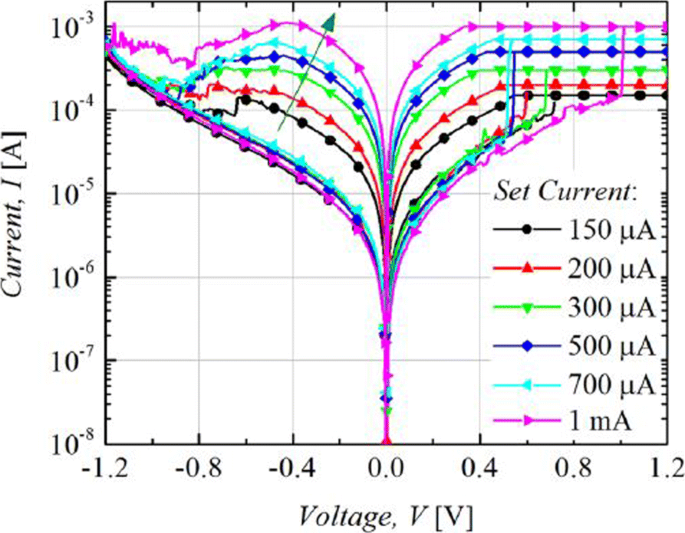
Multilevel characteristics of Ti/Ta2 O5 /Pt RRAM obtained by controlling the compliance current. ‘Reproduced from [127], with the permission of AIP Publishing’
The formation of the CF and its corresponding widening with an increase in I cc is the attributed mechanism of multilevel per cell (MLC) in compliance current (I cc ) mode as depicted schematically in Fig. 12. With an increase in the size of CF because of an increase of I cc , the resistance of the CF decreases and hence results in multiple LRS levels for different values of I cc . It is also observed that I reset increases with increasing I cc as higher power is required to rupture the CF having larger diameter.
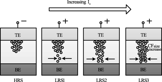
Schematic illustration of multiple resistance states in RRAM cell obtained by varying compliance current ‘I cc ’ [98]
MLC by Controlling Reset Voltage
The MLC characteristics in a RRAM cell can also be obtained by controlling the reset voltage (V reset ) while (I cc ) is maintained constant. In this case, the typical MLC I-V curves of TiN/HfO x /AlO x /Pt-based RRAM cell [128] by applying different (V reset ) of − 2.1 V, − 2.7 V and − 3.3 V are shown in Fig. 13.
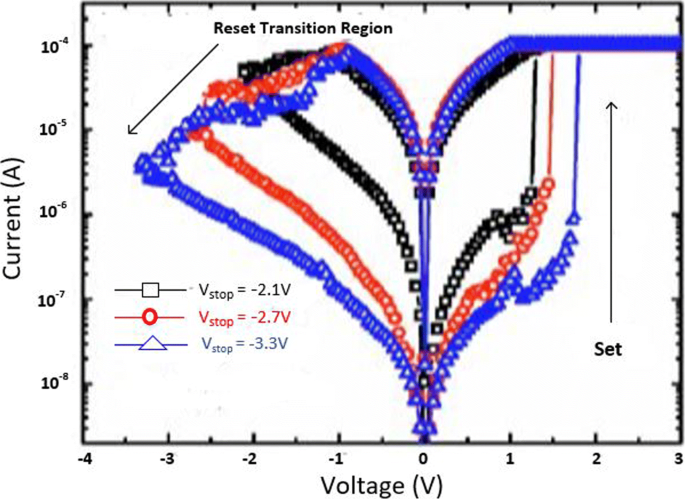
Multilevel characteristics of TiN/HfO x /AlO x /Pt RRAM obtained by controlling the reset voltage. ‘Reproduced from [128], with the permission of AIP Publishing’
It is observed that with an increase in (V reset ), the HRS current (I HRS ) decreases; thus, multiple HRS levels with the same LRS resistance are obtained. In addition, the set voltage (V set ) also increases as V reset is increased while as the I reset remains almost constant.
The decrease in I HRS with the increase in reset voltage is primarily due to the increase in the gap between the metal electrode and tip of the CF as depicted in Fig. 14. The more the magnitude of the V reset , the larger the gap and thus the higher the value of resistance. Therefore, an increase in the gap between the CF tip and bottom electrode (BE) with increasing reset voltage results in multiple resistance levels of HRS. It is observed that the devices in which the I reset shows a gradual change in current instead of the abrupt change during the ‘reset’ operation, the change in HRS resistance in such devices can be due to decrease in the size of the conductive filament (CF) as V reset is increased. This approach is more viable practically for cross-point architectures as it requires relatively lower complex circuitry.
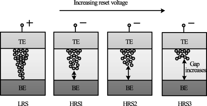
Schematic illustration of multiple resistance states in RRAM cell obtained by varying reset voltage ‘V reset ’ [98]
MLC by Varying Program/erase Pulse Width
MLC characteristics can also be obtained by varying the program/erase pulse width while the amplitude of the pulse is maintained constant [23]. In HfO x -based RRAM [128], three HRS levels were demonstrated by varying the width of the reset pulse from 50 ns to 5 μ s. This method of obtaining MLC characteristics in RRAM is relatively easier; however, this scheme is energy inefficient. This drawback limits the application of this method to obtain reliable characteristics in the RRAM cell. The higher energy consumption of the RRAM device was confirmed on the comparison of the transient responses between the reset pulse amplitude and pulse width control. This is particularly due to the higher unwanted energy dissipation as the thermal energy in the resistive switching material.
A summary of RRAM devices exhibiting multiple resistance states is shown in Table 4. As is evident from the table, various RRAM devices with multiple resistance states have been reported. Till date, however, only 8 resistance states have been demonstrated in a single RRAM cell either by varying I cc or V reset . Therefore, there is a huge scope for increasing the number of resistance states in the RRAM cell, thus enhancing its storage density.
Modeling of RRAM Devices
Modeling plays a very critical role in development of devices utilizing semiconductor technologies. To fully understand device operation and to optimize the performance, an accurate model is of great importance. A number of RRAM models with varying features and accuracy have been proposed [129]. This section discusses the characteristics and attributes of the various commonly used RRAM models popular.
Stanford/ASU Model
One of the most popular physics-based RRAM models is the Stanford/ASU RRAM model [130–132], proposed by Guan et al. and Chen et al. This model was applied to validate the I-V switching characteristics of HfO2 RRAM [128] and includes the effect of Joule heating and temperature change on the switching of RRAM devices.
This model is dependent on the CF growth inside a dielectric switching layer. The filament gap, i.e. the gap between the tip of the CF and top electrode, is the internal state variable for this model. The growth of CF inside a dielectric is attributed to the oxygen ion movement and regeneration and recombination of oxygen vacancies [133]. Thus, the rate of change of filament gap (g) is given as [130]:
$$ {\frac{dg}{dt}} =V_{\tiny{0}}.\exp\bigg({{\frac{-E_{a},m}{k_{b}.T}} }\bigg). {\text{Sinh}} \bigg({\frac{qa_{h}\gamma V}{L.k_{b}.T}}\bigg) $$ (1)où E un is the activation energy, V is the magnitude of the voltage applied across the device, L is the switching material thickness, a h is the hopping distance, γ is the local field enhancement factor, V 0 is the velocity containing attempt to escape frequency, K b is the Boltzmann constant, q is the elementary unit charge and T is the temperature of the conductive filament.
The spatial variation in the gap size is accounted for in this model, in addition to the variations which arise due to the stochastic property of the ion process. A noise signal is added to the gap distance to account for these variations as [130]:
$$ g_{|t+\Delta t} =F \Big[ g_{|t}, {\frac{dg}{dt}} \Big] + \delta_{g}\times\tilde{X}(n)\Delta t, n ={\frac{t}{T_{GN}}} $$ (2)où Δ t is the simulation time step, the function F represents time evolution of gap size fromt to Δ t. \(\tilde {X}\)(n) is a zero mean Gaussian noise sequence. T GN is the time interval after which \(\tilde {X}\)(n ) changes to next random value.
The variation in the gap size δ g depends on kinetic energy of ions and filament temperature as [130]:
$$ \delta_{g} (T) ={\frac{\delta^{\tiny{0}}_{g}}{\bigg\{ 1+\exp \Big({\frac{T_{\text{crit}}- T}{T_{\text{smith}}}} \Big) \bigg\}}} $$ (3)where \(\delta ^{0}_{g}\) and T smith are fitting coefficients to match the resistance distribution curves to experiments and T crit is a threshold temperature above which the gap size changes significantly.
This model shows strong dependence on temperature; thus, there is a need to account for the change of ‘T’ . With change in cell characteristics, the dynamic inner domain temperature T changes significantly, while the outer domain assumed to be at uniform and stable temperature (T bath ), is related as [130]:
$$ c_{p} {\frac{dT}{dt}} =V(t).I(t) - k(T-T_{\text{bath}}) $$ (4)where C p is the effective heat capacitance of inner domain, V (t) I (t) represents the Joule heating and k is the effective thermal conductivity.
Using a generalized conduction mechanism, the current conduction is defined as [130]:
$$ I(g,v) =I_{\tiny{0}}.\exp\bigg({{\frac{-g}{g_{\tiny{0}}}} }\bigg){\text{Sinh}} \bigg({\frac{V}{V_{\tiny{0}}}}\bigg) $$ (5)où je 0 , g 0 et V 0 are the fitting parameters to match experimental results.
One of the significant features of this model is its implementation in neuromorphic applications and RRAM synaptic device design [134], giving the model a great degree of flexibility and further scope for implementation in various neuromorphic systems.
Physical Electro-thermal Model
Physical electro-thermal model was developed by Kim et al. [135] and implemented with tantalum pentoxide (Ta2 O5 ) -based bilayer RRAM [136–138]. This physical model solves the differential equations based on finite element solving method. This model also makes use of electrothermal physics phenomenon approach for modeling [139], thus giving it advantage in terms of flexibility to incorporate finite element method (FEM) solver to simulate the system very accurately. However, the drawback of this approach is its difficulty in implementation for SPICE and Verilog circuit solvers.
This model describes CF as a doped region having oxygen vacancies as dopants with CF extending from the top to the bottom electrode of the device. To describe the drift-diffusion of vacancy migration, this model assumes the same equation can be used to describe both the processes of oxygen ions and vacancies. The ion model by Mott and Gurney [140] is employed here to describe the process given as [135]:
$$ {\frac{dn_{D}}{dt}} =\Delta \times \bigg(D_{s}.\Delta_{n\tiny{D}}- \mu v n_{D} \bigg) + G $$ (6)où D s describes the diffusion process, v gives the drift velocity of vacancies and G is the CF growth rate which actually describes the SET process. The parameters are defined as [135]:
$$ D_{s} ={\frac{1}{2}} \times a^{2} \times f_{e} \times \exp \bigg({\frac{- E_{a}}{k_{B}T}} \bigg) $$ (7) $$ v =a_{h} \times f \times \exp \bigg({\frac{- E_{a}}{k_{B}T}} \bigg) \times {\text{Sinh}} \bigg({\frac{q a_{h}E}{k_{B}T}} \bigg) $$ (8) $$ G =A \times \exp \bigg({\frac{- (E_{a}-ql_{m}E)}{k_{B}T}} \bigg) $$ (9)where l m is the mesh size.
These equations govern the physical transformation of the device during SET and RESET transition, thus essentially controlling the CF growth and rupture.
Huang’s Physical Model
Huang’s physical model developed by Huang et al. [141, 142] is a very comprehensive physical model for RRAM device as it takes into account both the CF width and the gap of filament to electrode as the factors affecting the state variable dynamics. In addition, temperature distribution is also accounted for in this model.
SET/RESET process is considered as a result of generation/recombination process of oxygen ions (O 2− ) and oxygen vacancies (V 0 ). During the SET process, CF starts to evolve from the tip of the top electrode (T.E) and elongates in radius with increase in voltage, resulting in final width ‘W’ of the C.F. This model assumes symmetrical cylindrical shape of the C.F. During RESET process, CF ruptures starting from TE till it dissolves completely with increase in voltage. The filament gap distance ‘x’ is defined as the gap between active electrode layer (T.E) and the tip of the C.F.
Thus, for the SET process, parameter ‘W’ acts as state variable, while for RESET, parameter ‘x’ acts as state variable. Therefore, \(\frac {dx}{dt}\) and \(\frac {dw}{dt}\) define the dynamics of the device during the SET/RESET transition.
During the first reset process, CF reduction rate, i.e. release of O 2− , is by the electrode is expressed as [142]:
$$ {\frac{dx}{dt}} =a \times f\times \exp \bigg({\frac{- E_{i}-\gamma Z_{e}V}{k_{B}T}} \bigg) $$ (10)For O 2− hopping within the oxide layer, the CF reduction rate with ‘a’ being the distance between two V0 is given as [142]:
$$ {\frac{dx}{dt}} =a \times f\times \exp \bigg({\frac{- E_{h}}{k_{B}T}} \bigg) {\text{Sinh}} \bigg({\frac{ a_{h}Z_{e}E}{k_{B}T}} \bigg) $$ (11)For the case of RESET process when dominated by recombination between O 2− and V0 is expressed as [142]:
$$ {\frac{dx}{dt}} =a \times f\times \exp \bigg({\frac{- \Delta E_{r}}{k_{B}T}} \bigg) $$ (12)In the initial step of the SET process dominated by recombination of oxygen vacancies with thin CF initially grown is given by [142]:
$$ {\frac{dx}{dt}} =-a \times f_{e}\times \exp \bigg({\frac{- E_{a}-\alpha_{a} Z_{e}E}{k_{B}T}} \bigg) $$ (13)Here, Z and α g are the fitting parameters.
For the second step, CF grows along its radial direction and is defined as [142]:
$$ {\frac{dw}{dt}} =\bigg(\Delta w + {\frac{\Delta w^{2}}{2w}} \bigg) \times f_{e}\times \exp \bigg({\frac{- E_{a}-\gamma Z_{e}v}{k_{B}T}} \bigg) $$ (14)The current flowing through the device is modeled as a correlation of hopping current with voltage and gap distance expressed by [134] as:
$$ i =i_{0}. \exp \bigg({\frac{-x}{x_{T}}} \bigg) {\text{Sinh}} \bigg({\frac{v}{v_{T}}} \bigg) $$ (15)This model is validated in HfO x /TiO x system [141, 142], and a pretty accurate match between the experimental and simulation results is obtained. Although this model accounts for the significant processes which affect the RRAM operation, however, it has some limitations. The most critical one is being incompatible with the SPICE and Verilog-A.
Filament Dissolution Model
This model was developed exclusively for unipolar RRAM devices by Russo et al. [143–145], however was later modified for bipolar RRAM devices [139, 146] also. Filament dissolution model is based on rupture of CF under the effect of significant temperature change caused due to Joule heating.
One of the significant advantages of this model is that it utilizes the simple partial differential equations to account for the device current and temperature changes due to Joule heating as well as the dissolution velocity. The conduction of current within the device is described by Poisson’s equation [144] as:
$$ \triangledown \times \bigg({\frac{1}{\varphi}\triangledown_{v}} \bigg) =0 $$ (16)Ici, φ is the oxide resistivity and v defines the electric potential due to the application of external bias voltage to one of the electrodes while the other electrode is connected to ground.
The CF is divided into a number of mesh grids and at each point of the mesh grid the temperature is calculated to describe the rupture of CF. The Fourier steady-state heat equation describes this effect as [144]:
$$ -\triangledown \times \bigg(k \triangledown T \bigg) =\varphi J^{2} $$ (17)où k represents the oxide layer thermal conductivity, J is the current density and T is the device temperature.
The temperature ‘T’ of the device increases to the critical temperature, after which the device is reset and the CF dissolution takes place. The dissolution factor is modeled as [144]:
$$ V_{\text{DIS}} =V_{\text{DIS}-F}. \exp \bigg({\frac{- E_{a}}{k_{B}T}} \bigg) $$ (18)où E un is the activation energy, k b est la constante de Boltzmann, V DIS−F is a fitting parameter and V DIS is velocity of CF boundary towards symmetry axis.
The resistivity of CF is temperature-dependent and is described as [144]:
$$ \varphi_{\text{CF}} (T) =\varphi_{\mathrm{CF-RT}} \Big[ 1 + C (T-T_{0}) \Big] $$ (19)où C is the experimentally calculated temperature coefficient of resistivity and φ C F −R T is the standard CF resistivity at room temperature.
COMSOL Multiphysics Software [147] is used for solving the coupled equations for this RRAM model due to its multiphysics capabities and ability to handle such simulations.
Bocquet Bipolar Model
Bocquet bipolar model [148] describes the bipolar oxide-based resistive switching memories utilizing a physics-based modeling approach. Bocquet bipolar model describes the electroforming process of RRAM device, inaddition to utilizing some of the characteristics from Bocquet unipolar model [149] and modifies them significantly according to the bipolar switching characteristics. In this model, the radius of the CF is the internal state variable which effectively governs the switching rate.
To model the electroforming stage, Bocquet bipolar model utilizes electroforming rate (τ Form ) which details the mechanism of conversion to switchable sub-oxide from pristine oxide. The electroforming stage is modeled as [148]:
$$ \tau_{\text{form}} =\tau_{\text{form}0} \times \exp \bigg({\frac{E_{a\text{Form}}-q \times \alpha_{s} \times V_{\text{cell}}}{k_{B}\times T}} \bigg) $$ (20) $$ {\frac{dr_{\text{CFmax}}}{dx}} ={\frac{r_{\text{work}}-r_{\text{CFmax}}}{\tau_{\text{form}}}} $$ (21)où E un Form is the activation energy for electroforming, τ form0 is the nominal forming rate, α s is the charge transfer coefficient, V cell is the voltage applied between the top and bottom electrodes, r CF is the radius of CF which varies from 0 to r CFmax , q is the elementary charge of electron, T is the temperature of the device and k B is the Boltzmann constant.
The electrochemical redox reaction derived from Butler-Volmer equation [150] is used to describe the SET/RESET operation as [148]:
$$ \tau_{\text{Red}} =\tau_{\text{Redox}} \times \exp \bigg({\frac{E_{a}-q \times \alpha_{s} \times V_{\text{cell}}}{k_{B} \times T}} \bigg) $$ (22) $$ \tau_{Ox} =\tau_{\text{Redox}} \times \exp \bigg({\frac{E_{a}+q \times (1 - \alpha_{s}) \times V_{\text{cell}}}{k_{B} \times T}} \bigg) $$ (23)Here, τ Red et τ Ox are the reduction and oxidation rates, respectively. τ Redox is the effective reaction rate considering both reduction and oxidation reactions.
The switching rate is obtained by coupling the above two equations as [148]:
$$ {\frac{dr_{CF}}{dt}} ={\frac{r_{\text{CFmax}}-r_{\text{CF}}}{\tau_{\text{red}}}} - {\frac{r_{\text{CF}}}{\tau_{\text{Ox}}}} $$ (24)Bocquet bipolar model is a quite comprehensive model as it includes the temperature effects as well. The local filament temperature is coupled using heat equation and is given in Eq.(25), the temperature considering a cylindrical-shaped filament is given in Eq. (26). The maximum temperature reached into CF at x =0, the middle of the filament is given in Eq. (27) and the equivalent electrical conductivity in the work area (σ éq ) is given in Eq. (28).
$$ \sigma_{x} \times F(x)^{2} =- k_{th}.{\frac{d^{2}T(x)}{dx^{2}}} $$ (25) $$ T(x) =T_{\text{amb}}+{\frac{V^{2}_{\text{cell}}}{2. L^{2}_{x}.k_{th}}} \bigg({\frac{L^{2}_{x}}{4}- x^{2}} \bigg) \sigma_{eq} $$ (26) $$ T =T_{\text{amb}}+{\frac{V^{2}_{\text{cell}}}{8. k_{th}}} \sigma_{eq} $$ (27) $$ \sigma_{eq} =\sigma_{CF}.{\frac{r^{2}_{\text{CF}}}{r^{2}_{\text{work}}}} - \sigma_{Ox}. {\frac{r^{2}_{\text{CFmax}}-r^{2}_{\text{CF}}}{r^{2}_{\text{work}}}} $$ (28)where (σ x ) is the local electrical conductivity, F (x ) is the local electric field, σ CF is the electrical conductivity of the conductive filament, k ème is the thermal conductivity and T amb is the ambient temperature.
It must be mentioned here that temperature increases with increase in radius of the CF, resulting in self-accelerated reaction due to a positive feedback loop. The self-limited reaction also referred to as SOFT reset [151], on the other hand, occurs due to the decrease in temperature and radius of the CF during RESET operation.
The total current flowing in OxRRAM is the sum of currents flowing in the conductive area (I CF ), the conduction through switchable sub-oxide (I sub−oxide ) and conduction through unswitched pristine oxide (I pristine ). The total current is as [148]:
$$ I_{\text{cell}} =I_{\mathrm{sub-oxide}} + I_{\text{CF}} + I_{\text{Pristine}} $$ (29) $$ I_{\text{CF}} =F.\pi. \sigma_{CF}.r^{2}_{CF} $$ (30) $$ I_{\mathrm{sub-oxide}} =F.\pi. \sigma_{Ox}. \big(r^{2}_{\text{CFmax}}- r^{2}_{CF}\big) $$ (31) $$ I_{\text{Pristine}} =S_{cell}.A.F^{2}. \exp {\frac{-B}{F}} $$ (32) $$ A ={\frac{m_{e}.q^{3} }{8\pi.h.m^{ox}_{e}.\phi_{b} }} $$ (33)The parameter B e is the metal-oxide barrier height (ϕ b )-dependent and is given as [148]:
$$ if \phi_{b}\geq qL_{x}F:B_{e} ={\frac{8 \pi \sqrt{2m^{ox}_{e} }}{3\times h\times q}} \Big[ \phi^{{\frac{3}{2}}}_{b}- (\phi_{b}-qL_{x}E)^{{\frac{3}{2}}} \Big] $$ $$ \text{otherwise}, B_{e} ={\frac{8 \pi \sqrt{2m^{ox}_{e} }}{3\times h\times q}} \times \phi^{{\frac{3}{2}}}_{b} $$ (34)where m e and \(m^{ox}_{e}\) are the effective electron masses into the cathode and oxide respectively, F =\(\frac {V_{\text {cell}} }{L_{x}}\) is the electric field across the active layer, h is the Planck constant and S cell is the section of the RRAM cell.
Discrete solutions are required to implement the model in an electrical simulator. This model accounts well in that aspect, making it suitable for simulation involving electrical circuits. This model implements equations in Eldo circuit simulator [152]. The discrete solutions are given as [148]:
$$ r_{\text{CFmax}_{i+1}} =\big(r_{\text{CFmax}_{i}}- r_{\text{work}} \big) \times e^{ {\frac{-\Delta t}{{\tau}_{\text{form}}}} } + r_{\text{work}} $$ (35) $$ r_{CF_{i+1}} =\bigg(r_{CF_{i}}- r_{\text{CFmax}_{i}} \times {\frac{\tau_{eq}}{\tau_{\text{Red}}}} \bigg) \times e^{ {\frac{-\Delta t}{{\tau}_{eq}}} } + r_{\text{CFmax}_{i}} \times {\frac{\tau_{eq}}{\tau_{\text{Red}}}} $$ (36) $$ \text{where} { \tau_{eq}} =\frac{\tau_{\text{Red}}\times \tau_{\text{Ox}} }{\tau_{\text{Red}}+\tau_{\text{Ox}}} $$ (37)This model has been verified against electrical characterization from an HfO2 -based system [153]. An important feature of this model is that it can account effectively for device to device variability [154, 155]. One of the major limitations of this model is the lack of current or voltage threshold.
This section presents in detail various characteristics and features of the RRAM models. A comparative analysis of the RRAM models discussed in this work is presented in Table 5.
Applications of RRAM
RRAM is seen as one of the standout candidates among the emerging memory technologies that has the potential for reforming the memory hierarchy primarily due to its high speed, the capability of non-volatile data storage, enhanced storage density and logic computing function. The various novel applications of RRAM are discussed in this section.
>Non-volatile Logic
The instruction codes and the data are transferred by making use of buses between various units in a computer system having von Neumann architecture because of the separate computing and memory unit. This data transferring process results increased energy consumption and time delay, which is commonly referred to as ‘von Neumann bottleneck’. For reducing the impact of von Neumann bottleneck [156], the computing process which utilizes RRAM crossbar array is suggested which alters the memory and computing operations in the same core. In addition, to obtain high integration density and low cost [157], two-terminal compact device structure of RRAM and its 4F 2 array architecture are highly beneficial. For example, to obtain simple Boolean logic functions such as ‘logic NOT’, ‘logic AND’, and ‘logic OR’, we require multiple transistors and each single transistor takes 8−10F 2 région. These logic functions can be realized by making use of two or three RRAM cells, resulting in total approximate area of around 10F 2 only [158].
Till date, several methods have been suggested for realizing Boolean logic functions [159, 160]. Boolean computing is significantly more established compared to existing non-Boolean computing paradigms such as neuromorphic computing and quantum computing. Therefore, energy and cost-efficiency of CPU or MCU can be enhanced without the need to develop new algorithms or software, although there is still a lack of technical solution on how to implement complex computing tasks in a crossbar array. Thus, most of research to date focusses on only basic logic level demonstration as it becomes quite complex to implement a whole computing unit using RRAM array.
Neuromorphic Computing
To overcome ‘von Neumann bottleneck’, one of the effective ways is brain-inspired neuromorphic computing which has shown promising potential in a wide range of complex and cognitive tasks like visual/audio recognition, self-driving, and real-time big-data analytics. Compared to CMOS-based neuromorphic network, neuromorphic computing based on RRAM-array offers advantages in terms of on-chip weight storage, online training, and scaling up to much larger array size [161–163]. In addition, the processing speed of RRAM improves by three orders of magnitude, whereas the power consumption rate is reduced by four orders of magnitude [164].
For realizing hardware-implemented neuromorphic computing paradigms, two methods are suggested:one among the strategies mimics the structure and working mechanism of biological neural networks while the other method works on accelerating the existing artificial neural network (ANN) algorithms. In a neural network, a synapse is used to transfer spikes between different neurons in addition to storing information about the transferring weights. The information regarding weights can be acquired through certain learning rules such as spike-time-dependent plasticity (STDP) and spike-rate-dependent plasticity (SRDP) [165–167]. Although some of the works reported in the literature have tried to emulate such learning rules on RRAM devices, it is however quite complicated to extend such types of bioinspired learning rules to a complex task as the theoretical algorithm is still lacking.
A practically viable approach is to map an ANN to a RRAM-based neuromorphic network directly. Some advanced tasks such as pattern and speech recognition have been demonstrated based on this method [166–169]. Although very promising, RRAM-based synapse is still far from being applied as various issues such as material optimization, variation suppressing, control circuit design, architecture, and algorithms design for analog computing need to be addressed effectively.
Security Application
The security aspect has become more prominent with rapid developments in the field of information technology; thus, there is a need for hardware-based security-integrated circuits. In contrast to security circuits based on CMOS logic which exploits the random nature of the semiconductor manufacturing process, security circuits based on RRAM are more robust to attacks of various types due to its completely random switching mechanisms [170, 171]. It must be noted that for security applications, larger variation of RRAM device parameters such as random telegraph noise (RTN), resistance variations and probabilistic switching is desirable, which is quite different from memory applications that require a smaller degree of variation among numerous parameters.
A novel security feature commonly referred to as physical unclonable function (PUF) [172], based on RRAM is proposed for device authentication (strong PUF) and key generation (weak PUF) applications. Significantly larger number of input-output pairs [also called challenge-response pair (CRP) are required for strong PUF, while only a small amount of CRPs of extremely higher reliability are required for weak PUF [173]. Although, PUFs based on RRAM have demonstrated remarkable performance; however, still more practical demonstrations and further evaluations are required to work out the maturity of this new primitive within the field of hardware security.
Non-volatile SRAM
Volatile memory technologies like SRAM and DRAM may consume over half of the static power within the current mobile SoC chips. Thus, to attain fast parallel memory operations, reduced area and low-energy consumption, RRAM-based non-volatile SRAM (nvSRAM) was proposed [174] in which two RRAM cells are stacked on eight transistors, forming an 8T2R structure. Also, non-volatile ternary content-addressable memory (TCAM) having 4T2R cell structure [175] and non-volatile flip flops having reduced stress time and write power based on RRAM have been demonstrated recently [176].
Challenges and Future Outlook
During the past several years, research in the field of emerging memory technologies has grown significantly and several prototype RRAM products have been developed demonstrating the potential for high-speed and low-power embedded memory applications. RRAM is one of the most promising memory technologies because of the advantages of simple structure, compatibility with the existing CMOS technology, good switching speed and ability to scale to the smallest dimensions. As a matter of fact, currently the Flash memory technology is facing difficulties to reduce to lower dimensions and as such RRAM is emerging as a potential replacement especially for fast operation and medium size storage density memory applications.
One of the most critical aspects that needs to be thoroughly investigated is that of the reliability of RRAM. A mechanism must be developed to ensure the detection of the operation failure of the device. Also designing circuits, e.g. a test element group (TEG) design for robust signal sensing, is one of the critical challenges for the emergence of RRAM devices. To achieve high-density memory operation in RRAM, the 1D1R operation is essential. This can be realized by operating the RRAM device in the unipolar mode. However, in the unipolar operation, higher current is needed for the reset process as compared to that of the bipolar operation. This is due to the fact that thermal effect plays a significant role in the unipolar reset process. Thus, to realize a high-density 1D1R RRAM array, the thermal effects both inside and outside a memory element needs to be considered. Also note that till date, in a single RRAM device, no technology has simultaneously reported fast switching, low power, and stable operation. Although, the endurance of RRAM has been reported as high as 10 12 [59], it is still not enough to be able to replace DRAM. The RRAM possesses the switching speed fast enough for DRAM replacement and the materials used in the fabrication for RRAM are very similar to that of DRAM, it becomes a critical challenge to improve the endurance characteristics of RRAM. To improve the endurance characteristics, it is necessary to control the oxygen movement between the electrode and the oxide layer at the interface. It is suggested to insert the second metal layer at the interface which can be easily oxidized and acts as an oxygen reservoir to prevent oxygen from penetrating into the electrode during the resistance switching. The most critical challenge hindering RRAM development till date is the proper understanding of the device switching mechanism which is since long being debated by researchers across the globe. The inconsistent switching mechanism of various reported RRAM devices is believed to be because of variation in the fabrication process, and thus, more rigorous analysis is needed in the future for obtaining a better understanding of the switching mechanism of RRAM devices. The aforesaid issues need to be handled effectively before implementing RRAM in future memory applications. Although, RRAM is highly attractive for use in neuromorphic computations, the biggest challenge to industrialize RRAM lies in its ability to tackle the variability issues, not only at nominal operating conditions but also at high temperatures before they can be used in a wide variety of applications.
Conclusion
This review article provides a brief introduction into the advancement of the memory architecture, the current trends and the limitations while providing a valuable insight into the field of emerging memory technologies. A detailed discussion, highlighting the importance of RRAM, its structure, working mechanism, and classification, has been presented. The key performance parameters and their effect on the RRAM operation has also been detailed within the current manuscript. An elaborate study on the MLC capability of RRAM, along with the methodology have been presented. The manuscript also discusses the important features of the widely accepted RRAM models. The implementation of RRAM for various important applications such as non-volatile logic, neuromorphic computing, security, and non-volatile SRAM have been highlighted. Although, significant success has been achieved in RRAM technology; however, more work is needed as RRAM still suffers from various challenges in terms in terms of high operation current, lower resistance ratios, and reliability issues. More efforts in research should aim to develop methods to achieve faster programming/erasing, lower power consumption, enhancing the storage density by implementing multilevel storage capability and improvement in the fabrication process for enhanced uniformity. In addition, renewed focus should be towards use of RRAM in embedded memory and non-volatile logic applications as breakthroughs in these fields are much more exciting and significant. With continued work and improvements, it is imperative that RRAM devices will be a standout technology for future non-volatile memory applications.
Disponibilité des données et des matériaux
Not applicable.
Abréviations
- RRAM:
-
Mémoire vive résistive
- MLC:
-
Multilevel cell
- RTN :
-
Bruit télégraphique aléatoire
- DRAM :
-
Dynamic random access memory
- SRAM:
-
Static random access memory
- PCM :
-
Phase change memory
- STT-MRAM:
-
Spin-transfer torque resistive random access memory
- LRS :
-
Low resistance state
- HRS :
-
High resistance state
- MTJ:
-
Magnetic tunneling junction
- MIM :
-
Métal-isolant-métal
- MoM:
-
Metal-oxide-metal
- PLD :
-
Pulse laser deposition
- ALD :
-
Dépôt de couche atomique
- V set :
-
Set voltage
- V reset :
-
Reset voltage
- V f :
-
Tension de formation
- Je CC :
-
Compliance current
- CBRRAM:
-
Conductive bridge resistive random access memory
- OxRRAM:
-
Oxygen vacancies resistive random access memory
- ECM:
-
Electrochemical metallization memory
- VCM:
-
Valence change memory
- CF :
-
Filament conducteur
- BE :
-
Électrode inférieure
- TEM :
-
Microscopie électronique à transmission
- I-V:
-
Courant-tension
- 1T-1R:
-
1-Transistor 1-RRAM
- ANN:
-
Artificial neural network
- STDP:
-
Spike-time-dependent plasticity
- SRDP:
-
Spike-rate-dependent plasticity
- PUF:
-
Physical unclonable function
- CRP:
-
Challenge-response-pair
- nvSRAM:
-
Non-volatile SRAM
- TCAM:
-
Ternary content addressable memory
- TEG:
-
Test element group
Nanomatériaux
- 13 types de matériaux réfractaires et leurs applications
- Amélioration des performances et de la sécurité des wearables IoT
- Cervoz :choisir le bon stockage flash pour les applications industrielles
- Caractéristiques de commutation résistive bipolaire des dispositifs RRAM à structure tricouche HfO2/TiO2/HfO2 sur des substrats revêtus de Pt et de TiN fabriqués par dépôt de couche atomique
- Mémoire résistive ZrO2/ZrO2 − x /ZrO2 sans conformité avec comportement de commutation multi-états interfacial contrôlable
- Une RRAM SRAM 4T intégrée avec charge de commutation résistive à auto-inhibition par un processus logique CMOS pur
- Mécanisme de conduction et endurance améliorée dans la RRAM à base de HfO2 avec traitement de nitruration
- Étude collective sur la modélisation et la simulation de mémoires résistives à accès aléatoire
- Nanowebs graphiques macroporeux hiérarchiquement présentant des performances de stockage de charge ultra-rapides et stables


