


Principes métallurgiques dans le traitement thermique des aciers
Principes métallurgiques dans le traitement thermique des aciers
Le traitement thermique des aciers est effectué pour obtenir les changements souhaités dans les propriétés de structure métallurgique des aciers. Par traitement thermique, les aciers subissent d'intenses modifications de leurs propriétés. Des structures en acier normalement très stables sont obtenues lorsque l'acier est chauffé à l'état austénitique à haute température, puis refroidi lentement dans des conditions proches de l'équilibre. Ce type de traitement thermique, normalement connu sous le nom de recuit ou de normalisation, produit une structure qui a un faible niveau de contraintes résiduelles bloquées dans l'acier, et les structures peuvent être prédites à partir du diagramme d'équilibre Fe (fer)-C (carbone). Cependant, les propriétés qui sont le plus souvent requises dans les aciers sont une résistance et une dureté élevées et celles-ci s'accompagnent généralement de niveaux élevés de contraintes résiduelles. Celles-ci sont dues aux structures métastables produites par le refroidissement hors d'équilibre ou la trempe à partir de l'état austénitique.
Structure et phases cristallines
La structure cristalline du Fe pur à l'état solide est connue pour exister dans deux états allotropiques. A partir de la température ambiante et jusqu'à 910°C, Fe possède un réseau cubique centré (bcc) et est appelé alpha-Fe. À 910 °C, les cristaux alpha-Fe se transforment en cristaux gamma-Fe possédant un réseau cubique à faces centrées (fcc). Les cristaux gamma conservent leur stabilité jusqu'à une température de 1400 deg C. Au-dessus de cette température, ils acquièrent à nouveau un réseau bcc appelé cristaux delta. Les cristaux delta ne diffèrent des cristaux alpha que dans la région de température de leur existence. Fe a deux constantes de réseau, à savoir (i) 0,286 nm pour les réseaux bcc (alpha-Fe, delta-Fe) et (ii) 0,364 nm pour les réseaux fcc (gamma-Fe). À basse température, l'alpha-Fe présente une forte caractéristique ferromagnétique. Cela disparaît lorsqu'il est chauffé à environ 770 ° C, car le réseau perd son ordre de spin ferromagnétique. L'état de Fe au-dessus de 770 degrés C est appelé bêta-Fe. Le réseau des cristaux bêta paramagnétiques est identique au réseau des cristaux alpha.
En passant d'une forme à une autre, Fe est capable de sous-refroidir. Cela provoque une différence dans la position des points de transformation sur le chauffage et le refroidissement. La différence dépend de la vitesse de refroidissement et est appelée hystérésis. Les lettres « c » et « r » indiquent si la transformation est due au chauffage ou au refroidissement. De plus, le changement de densité d'alpha-Fe lorsqu'il se transforme en gamma-Fe entraîne un changement brusque du volume du matériau. Parfois, il engendre des contraintes qui dépassent la limite d'élasticité et conduisent à la rupture. La densité du gamma-Fe est d'environ 4 % supérieure à celle de l'alpha-Fe.
Diagramme d'équilibre fer-carbone
La structure des aciers, qui sont des alliages Fe-C, peut contenir soit du C pur (graphite) soit un composé chimique connu sous le nom de cémentite (Fe3C) comme constituant enrichi en C. La cémentite est présente même dans les aciers refroidis relativement lentement (un long maintien à des températures plus élevées est généralement nécessaire pour décomposer Fe3C en Fe et C). Pour cette raison, le diagramme d'équilibre Fe-C est fréquemment traité comme le diagramme d'équilibre Fe-Fe3C. Le diagramme Fe-C est stable, tandis que le diagramme Fe-Fe3C est métastable. Le diagramme d'équilibre Fe-C incorporant à la fois le diagramme stable Fe-C et le diagramme métastable Fe-Fe3C est donné à la figure 1. Les lignes pointillées représentent le diagramme Fe-C stable et les lignes pleines indiquent le diagramme métastable Fe-Fe3C. P>
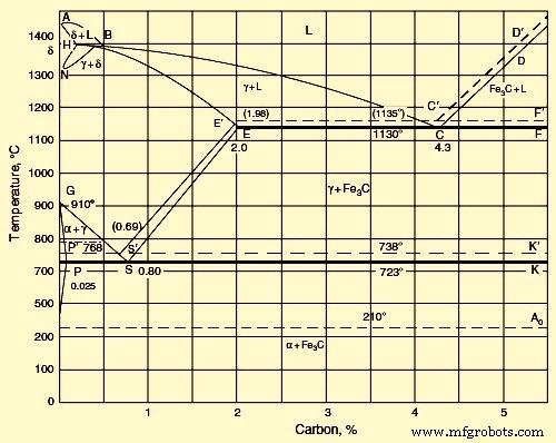
Fig 1 Diagramme fer-carbone
Dans le diagramme métastable Fe-Fe3C, les réseaux des formes allotropiques de Fe (delta, gamma et alpha) servent de sites de formation de solutions delta, gamma et solides de C dans Fe. Lorsque les aciers appauvris en C cristallisent, des cristaux de la solution solide delta précipitent au niveau du liquidus AB et du solidus AH. La solution solide delta a un réseau bcc. A la température maximale de 1490 deg C, la solution delta contient 0,1 % C (point H). A 1490°C, une réaction péritectique a lieu entre la solution delta saturée et le liquide contenant 0,5 % de C (point B). En conséquence, la solution solide gamma de C dans gamma Fe est formée. Il contient 0,18 % de C (point I).
Si la teneur en C est supérieure à 0,5 %, la solution solide gamma cristallise directement à partir du liquide (au liquidus BC et au solidus IE). A 1130°C, la solubilité limite du C dans le gamma Fe est proche de 2,0 % (point E). La diminution de la température à partir de 1130 deg C conduit à abaisser la solubilité du C dans le gamma-Fe au niveau de la raie ES. À 723 deg C, la solubilité du C est de 0,8 % (point S). La ligne ES correspond à la précipitation de Fe3C de la solution gamma.
Lorsque la teneur en C augmente, la température à laquelle le réseau gamma se transforme en réseau alpha diminue, et la transformation a lieu sur l'intervalle de température correspondant aux courbes GS et GP. La courbe de précipitation en phase alpha GS coupe la courbe de précipitation de Fe3C ES. Le point S est un point eutectoïde avec les coordonnées 723 degrés C et 0,80 % C. À ce point, une solution alpha saturée et un précipité de Fe3C forment simultanément la solution gamma de concentration eutectoïde. Le réseau de la solution solide alpha est identique au réseau de la solution solide delta. À la température eutectoïde de 723 deg C, la solution solide alpha contient 0,02 % de C (point P).
Un refroidissement supplémentaire entraîne une diminution de la solubilité du C dans alpha-Fe, et à température ambiante, elle équivaut à une petite fraction de pour cent (point D). Lorsque la teneur en C est de 2 % à 4,3 %, la cristallisation commence par la précipitation de la solution gamma au niveau de la ligne BC. Une augmentation de la teneur en C au-dessus de 4,3 % provoque une précipitation de Fe3C au niveau de la ligne CD. La précipitation de la phase primaire excédentaire dans tous les alliages de fer contenant plus de 2,0 % C est suivie d'une cristallisation eutectique de la solution gamma et de Fe3C au point C, dont les coordonnées sont 1130 deg C et 4,3 % C. La raie Ao est associée à une transformation qui est une transition de l'état ferromagnétique à l'état paramagnétique.
Dans le cas du diagramme d'équilibre Fe – C stable, en raison des très faibles vitesses de refroidissement, le C (graphite) peut cristalliser directement à partir du liquide. Dans ce cas, un mélange eutectique d'austénite et de graphite se forme à la place de l'eutectique d'austénite et de cémentite. Les lignes pointillées de la figure 1 symbolisent le système Fe-graphite. Ces raies sont à des températures plus élevées que les raies du système Fe-Fe3C. Cela confirme la plus grande stabilité et la proximité d'un équilibre complet du système Fe-graphite. Ceci est également étayé par le fait que le chauffage des aciers à haute teneur en C avec une grande quantité de Fe3C conduit à sa décomposition illustrée par l'équation Fe3C =3Fe + C.
A des vitesses intermédiaires de refroidissement, une partie de l'acier peut cristalliser selon le système graphite et l'autre partie selon le système cémentite. Les lignes d'équilibre de phase dans les diagrammes des deux systèmes peuvent être déplacées en fonction de taux de refroidissement particuliers. On observe un déplacement prononcé pour les raies de précipitation de la solution solide de C dans le gamma-Fe (austénite). Pour cette raison, le diagramme n'est complètement vrai que pour les aciers qui sont exposés à une vitesse de refroidissement relativement lente.
Influence du carbone
Une solubilité maximale de C dans alpha-Fe est observée à 721 degrés C et est égale à 0,018% C. Sous réserve de trempe, C peut rester dans la solution solide alpha, mais bientôt la précipitation des phases commence, par un mécanisme de vieillissement. Dans une solution solide, C peut former soit (i) une solution homogène, une distribution interstitielle statiquement uniforme ce qui est un cas rare, soit (ii) une solution inhomogène; avec la formation d'amas aux endroits où la structure du réseau cristallin est perturbée (joints de grains, dislocations). Ce dernier est l'état le plus probable de la solution solide. Les amas ainsi formés représentent un obstacle au mouvement des dislocations lors de la déformation plastique et sont responsables d'un développement inhomogène de la déformation en début d'écoulement plastique.
Pour analyser l'influence de la teneur en C sur les alliages Fe - C, chaque composant structurel doit être pris en compte. Les aciers à refroidissement lent comprennent la ferrite et la cémentite ou la ferrite et le graphite.
La ferrite est du plastique. À l'état recuit, la ferrite a un grand allongement (environ 40 %), est douce (la dureté Brinell est de 65 à 130 selon la dimension du cristal) et est fortement ferromagnétique jusqu'à 770 °C. À 723 °C, 0,22 % C se dissout dans la ferrite, mais à température ambiante, il ne reste que des millièmes de pour cent de C dans la solution.
La cémentite est cassante et présente une dureté plus élevée (la dureté Brinell est d'environ 800). Il est faiblement magnétique jusqu'à 210 degrés C et est un mauvais conducteur d'électricité et de chaleur. Il a un réseau rhombique compliqué. Normalement, une distinction est faite entre (i) le Fe3C primaire, qui cristallise à partir du liquide à la ligne CD, (ii) le Fe3C secondaire, qui précipite à partir de la solution gamma à la ligne ES, et (iii) le Fe3C tertiaire, qui précipite à partir de la solution a à la ligne PQ.
Le graphite est doux. C'est un mauvais conducteur d'électricité mais il transmet bien la chaleur. Le graphite ne fond pas même à des températures de 3000°C à 3500°C. Il possède un réseau hexagonal avec un rapport d'axe c/a supérieur à 2.
L'austénite est douce (mais plus dure que la ferrite) et ductile. L'allongement de l'austénite varie de 40 % à 50 %. Il a une conductivité thermique et électrique inférieure à celle de la ferrite et est paramagnétique. L'austénite possède un réseau fcc.
La structure de l'acier contenant 0 % – 0,02 % C est constituée de ferrite et de Fe3C tertiaire. Une nouvelle augmentation de la teneur en C conduit à l'apparition d'un nouveau composant structural qui est un eutectoïde de ferrite et de Fe3C (perlite). La perlite apparaît d'abord sous forme d'inclusions séparées entre les grains de ferrite puis, à 0,8 % C, occupe tout le volume. La perlite caractérise un mélange à deux phases, qui a généralement une structure lamellaire. Lorsque la teneur en C de l'acier est augmentée à une valeur supérieure à 0,8 %, du Fe3C secondaire se forme avec la perlite. Le Fe3C secondaire a la forme d'aiguilles. La quantité de Fe3C augmente à mesure que la teneur en C augmente. A 2 % C, il occupe 18 % du champ de vision du microscope. Un mélange eutectique apparaît lorsque la teneur en C dépasse 2 %. Dans les aciers refroidis rapidement, toute la phase excédentaire (ferrite ou Fe3C) n'a pas le temps de précipiter avant la formation d'un eutectoïde.
Les alliages à 3,6 % de C contiennent de la lédéburite (un mélange eutectique de solution solide de C dans gamma-Fe et Fe3C). Les alliages sont plus correctement classés avec les fontes blanches hypoeutectiques.
Températures critiques (de transformation)
Le carbone a un effet notable sur les transformations de Fe à l'état solide. La position s des lignes GS et NL dans le diagramme d'équilibre Fe-C montre qu'une augmentation de la teneur en C conduit à l'abaissement du point A3 et à l'élévation du point A4 par rapport à leurs homologues représentés sur la figure 1. C s'étend donc la plage de température de la phase delta.
Lorsqu'un eutectoïde (perlite) se forme, les courbes de chauffage et de refroidissement montrent un arrêt. Ceci est étiqueté comme le point A1 (Ac1 en chauffage et Ar1 en refroidissement). Ce phénomène se produit à 0,9 % C (point S du diagramme Fe–C). La précipitation de la ferrite dans les aciers hypo-eutectoïdes (au franchissement de la ligne GOS) se manifeste sur les courbes d'échauffement et de refroidissement par une inflexion qui est notée par le point A3. Le point correspond à la transformation gamma en alpha du fer pur. La précipitation de Fe3C (franchissement de la droite ES), qui précède la précipitation eutectoïde, se voit sur la courbe de refroidissement par une faible inflexion désignée par le point Acm (Ac,cm au chauffage et Ar,cm au refroidissement ). L'ajout de C a peu d'influence sur la température de transformation magnétique (point A2). Ainsi, la raie MO correspond à la transformation magnétique dans les aciers à faible teneur en C. Dans les alliages contenant des quantités plus élevées de C, cette transformation se produit au niveau de la raie GOS, qui correspond au début de la précipitation de la ferrite. Si la teneur en C est supérieure à celle correspondant au point S, alors la transformation magnétique coïncide avec la température A1.
La cémentite subit une transformation magnétique. Quelle que soit la teneur en C, la transformation a lieu à une température de 210°C à 220°C. Elle se produit sans hystérésis marquée, tout comme la transformation magnétique du Fe pur au point A2.
Transformation structurelle des aciers
Lorsque l'acier doit être durci, il est chauffé à haute température afin de convertir la structure totale en phase austénitique qui est une structure monophasée de Fe et C stable à haute température. Si cet acier chauffé est refroidi lentement, l'austénite se transforme en perlite, qui est la phase d'équilibre à température ambiante. Une structure perlitique est une structure recuite et est relativement douce avec de faibles propriétés physiques. Si l'acier chauffé est refroidi très rapidement, une structure dure et résistante appelée martensite se forme qui est une phase métastable de C dissous dans le fer. Cette phase peut être tempérée pour produire une structure de dureté inférieure qui est moins cassante. Des vitesses de refroidissement intermédiaires produisent d'autres structures telles que la bainite, bien que ce type de structure ne soit produit qu'en quantité dans un acier allié. L'acier eutectoide C produit principalement de la martensite ou de la perlite, selon la vitesse de refroidissement.
Transformation perlite austénitique
La transformation du réseau fcc d'austénite en réseau bcc de ferrite est entravée en raison de la présence de C dissous dans l'austénite. Le réseau d'austénite a suffisamment d'espace pour accueillir des atomes de carbone au centre de la cellule. Le réseau bcc de la ferrite n'a pas cet espace. De ce fait, la solubilité du C est considérablement réduite lors du passage de l'austénite à la ferrite. Au cours de la transformation bêta en alpha, la quasi-totalité du C précipite à partir du réseau d'austénite. Conformément au diagramme métastable Fe–Fe3C, il précipite sous forme de cémentite. Cette transformation peut être définie par trois voies interconnectées, à savoir (i) la transformation du réseau gamma-Fe en réseau alpha-Fe, (ii) la précipitation de C sous forme de Fe3C et (iii) la coagulation des carbures.
A la température du point A1, la transformation par les voies (i) et (ii) se déroule quasi simultanément, avec formation d'un mélange lamellaire de ferrite et de cémentite. Les atomes de C dissous sont distribués au hasard dans le réseau. De ce fait, Fe3C nuclée dans les régions riches en C et la ferrite dans les régions qui ont peu ou pas de carbone. Une telle redistribution du C se fait par diffusion et dépend de la température et du temps.
Lorsqu'un acier hypo-eutectoïde contenant moins de 0,8 % de C est soumis à un refroidissement lent, la transformation commence par la formation de ferrite aux joints de grains. Ce joint de grain agit comme centre de cristallisation de la ferrite. Le carbone est forcé à l'intérieur de la cristallite. Lorsque la ferrite précipite, une concentration nécessaire à la formation de ferrite est atteinte dans le volume central. Lorsque l'acier hypereutectoïde (C supérieur à 0,8 %) est soumis à un refroidissement lent, au franchissement de la ligne ES, Fe3C commence à précipiter au joint de grain. Ici, le joint de grain sert également de site de cristallisation.
La vitesse de diffusion du C dans les réseaux de gamma-Fe et alpha-Fe diminue rapidement lorsque la température est abaissée, puisque le coefficient de diffusion dépend de la température. Présentant une vitesse de refroidissement appropriée, le sous-refroidissement peut être amélioré à un point tel qu'il rend impossible la formation de perlite.
Dans la gamme des basses températures, le mécanisme de transformation et les caractéristiques de la structure formée dépendent uniquement de la température à laquelle la transformation a lieu. Compte tenu du degré de sous-refroidissement, trois gammes de température de transformation sont distinguées, à savoir (i) la gamme de la perlite, (ii) la gamme intermédiaire et (iii) la gamme de la martensite. Une transition continue d'un mécanisme de transformation à un autre peut avoir lieu sur ces plages de température. Les processus de transformation dépendent fortement de la teneur en C et autres éléments de l'acier. Ils peuvent commencer par un mécanisme plus rapide et se terminer par un mécanisme plus lent.
Dans la gamme des perlites, la transformation se caractérise par la formation simultanée d'un mélange de ferrite et de carbure. De la ferrite ou du carbure libre peut précipiter à la limite des grains d'austénite. Ici, la formation et la croissance des deux phases sont contrôlées par des processus de diffusion. La diffusion de Fe et d'autres éléments joue un rôle important. La finesse de la structure est améliorée à mesure que la température est abaissée, jusqu'à ce qu'un temps plus long soit nécessaire pour la cristallisation par diffusion de la ferrite et des carbures.
La perlite est un mélange mécanique de plaques de ferrite et de carbure qui se forme lors de la transformation dans la gamme de la perlite. La vitesse à laquelle les noyaux de cristallisation de la perlite se forment dépend de la sursaturation de l'austénite en carbure, qui augmente à mesure que la température diminue. La vitesse dépend également de la vitesse de diffusion, qui diminue avec la température. La croissance des îlots de perlite dépend principalement de la vitesse de diffusion des atomes de C et de Fe. Les autres facteurs sont (i) le degré de sursaturation et (ii) l'avantage d'énergie libre lors de la formation de la ferrite. Les îlots de perlite se développent non seulement par la formation de nouvelles plaques, mais également par la croissance ultérieure d'anciennes plaques dans toutes les directions. Les plaques de carbure se développent plus rapidement que les plaques de ferrite.
Le processus de formation de la perlite commence par la formation de noyaux de ferrite. De multiples alternances de nucléation de plaques de ferrite et de cémentite et de ramification des plaques des deux phases conduisent à la formation de plaques de perlite planes parallèles et en forme d'éventail. Les noyaux de perlite apparaissent principalement dans les régions du réseau avec des défauts de structure cristalline tels que des joints de grains, des carbures insolubles ou des inclusions non métalliques. Une caractéristique très importante de la perlite est l'espacement plaque à plaque. Les propriétés de résistance de l'acier s'améliorent avec une diminution de l'espacement.
La vitesse de formation de centres de cristallisation de Fe3C et de ferrite dans la gamme de la perlite s'accélère lorsque la température est abaissée. L'espacement plaque à plaque diminue lorsque la finesse de la structure augmente.
Une caractéristique importante qui affecte les propriétés de l'acier est la dimension de la colonie de perlite. Une diminution de la dimension de la colonie s'accompagne d'une croissance de la résistance aux chocs et d'une diminution de la fragilité. La température critique de fragilité dépend de la morphologie de la perlite. Ainsi, une perlite de résistance relativement élevée se forme dans le cas de la rupture de plaques de ferrite et de cémentite, formant une forte densité de dislocations à l'intérieur de la ferrite.
Une meilleure résistance à la rupture de la perlite est obtenue grâce à la sphéroïdisation des particules de Fe3C. La sphéroïdisation peut être facilitée par déformation de la perlite, chauffage ultérieur et maintien à une température proche de Ac1. Une autre méthode permettant d'obtenir une résistance et une ductilité relativement élevées de la perlite consiste en une déformation lors de la transformation de la perlite. Cela conduit à la formation d'une structure polygonale et à la sphéroïdisation de la cémentite. La limite d'élasticité (YS) du mélange ferrite-perlite dépend des propriétés de la ferrite et de la perlite de manière additive.
Transformation de l'austénite
Lors de la transformation de l'austénite dans les aciers hypo-eutectoïde et hyper-eutectoïde, la transformation perlitique est précédée par la précipitation des phases en excès à savoir la ferrite et la cémentite secondaire. La quantité relative de la phase en excès structurellement libre dépend du degré de sous-refroidissement de l'austénite. La quantité de ferrite ou de Fe3C en excès diminue avec une augmentation de la vitesse de refroidissement. Lorsqu'il y a un degré adéquat de sous-refroidissement, la formation d'une phase en excès en tant que composant structurel indépendant peut être évitée.
Lorsque l'acier hypo-eutectoïde contenant une petite quantité d'austénite eutectoïde est exposé à un refroidissement lent, la ferrite eutectoïde se développe sur les grains de ferrite en excès et l'eutectoïde Fe3C reste sous forme de couches intercalaires structurellement libres à la limite des grains. Dans l'acier hyper-eutectoïde, l'eutectoïde peut également être sujet à une dégénérescence structurelle. La cémentite, qui se forme à cause de la précipitation eutectoïde sous un très faible refroidissement en dessous du point A1 (au-dessus de 700°C) se dépose sur la cémentite secondaire. Des zones de ferrite structurellement libre sont remarquées à côté. Cette transformation eutectoïde, qui s'accompagne d'une séparation des phases, est considérée comme anormale. Dans la transformation eutectoïde normale, la ferrite et le Fe3C croissent ensemble sous forme de colonies avec une alternance régulière des deux phases. Dans le cas d'une transformation inhabituelle, un mélange grossier de ferrite et de Fe3C n'a pas de structure eutectoïde distinctive. Au cours d'une transformation eutectoïde, le mécanisme peut passer d'anormal à normal. Par conséquent, avec un refroidissement rapide et un sous-refroidissement prononcé de l'austénite, la transformation anormale peut être complètement supprimée.
En cas d'excès de ferrite dans les aciers hypo-eutectoïdes, la ferrite se trouve sous deux formes à savoir (i) des grains compacts équi-axiaux, et (ii) des plaques de Widmanstätten orientées. Des précipités compacts de ferrite hypo-eutectoïde apparaissent en grande partie à la limite des grains d'austénite alors que des plaques de Widmanstätten se forment à l'intérieur des grains. La ferrite de Widmanstätten n'est observée que dans les aciers à moins de 0,4 % C et à grains assez grossiers d'austénite. Au fur et à mesure que les dimensions des grains d'austénite diminuent, la part de ferrite sous forme de grains équiaxiaux augmente. La ferrite de Widmanstätten se forme sur l'intervalle de température de A3 (50 deg C) à 600 deg C à 550 deg C. Avec une augmentation de la teneur en C de l'acier, la part de la ferrite de Widmanstätten dans la structure diminue.
La ferrite de Widmanstätten est censée se former en raison d'un cisaillement gamma - réarrangement alpha du réseau, qui s'accompagne d'un mouvement interdépendant ordonné des atomes. Les grains équiaxiaux de ferrite se développent par un réarrangement diffusif normal du réseau avec une transition désordonnée des atomes à travers la frontière gamma/alpha.
L'une des méthodes utilisées pour renforcer les aciers consiste à doter une structure de ferrite hypo-eutectoïde contenant des précipités de carbure dispersés. Pour produire une telle structure, l'acier doit être chauffé jusqu'à ce que des carbures spéciaux se dissolvent dans l'austénite, puis refroidi rapidement afin d'empêcher la précipitation habituelle de carbure directement à partir de l'austénite avant que la ferrite hypo-eutectoïde ne commence à se former.
Transformation de la martensite
La transformation de la martensite est due à la trempe (refroidissement rapide) de la phase à haute température. Les principales caractéristiques de la transformation martensitique des aciers C sont données ci-dessous.
- La transformation de la martensite a lieu en raison du refroidissement rapide de l'acier à partir d'une température supérieure à A1, par exemple dans l'eau. En raison du refroidissement rapide, la précipitation par diffusion de l'austénite en un mélange à deux phases de ferrite et de carbure est supprimée. La concentration de C dans la martensite correspond à celle de l'austénite. La transformation de la martensite s'effectue sans aucune diffusion.
- La transformation de l'austénite en martensite commence à partir de la température de départ de la martensite (Ms). Ms ne dépend généralement pas de la vitesse de refroidissement. La martensite se forme sur un certain intervalle de température. La température particulière est déterminée par la teneur en C de l'acier.
- L'arrêt du refroidissement sur l'intervalle de température Ms-Mf (finition martensitique) suspend la formation de martensite. Cette caractéristique distingue la transformation martensitique de la transformation perlitique. Dans la transformation perlitique, la transformation se poursuit jusqu'au bout à une température constante en dessous du point A1, et le résultat final est une disparition complète de l'austénite compte tenu d'un temps de maintien isotherme suffisant. Avec la transformation martensitique, il reste une certaine quantité d'austénite résiduelle.
- La transformation martensitique n'a pas de période d'incubation. Une certaine quantité de martensite se forme instantanément en dessous de la température Ms.
- Lors du refroidissement en dessous de Ms, la quantité de martensite augmente rapidement en raison de la formation rapide de nouvelles plaques. Les plaques initialement formées ne grossissent pas avec le temps.
- Le réseau de martensite est régulièrement orienté par rapport au réseau d'austénite. Une certaine relation d'orientation existe entre les réseaux.
La température Ms caractérise un acier d'une certaine composition qui a subi un prétraitement particulier. Dans un acier donné, la transformation martensitique commence à la même température quelle que soit la vitesse de refroidissement. Cette température dépend de la composition de l'acier et diminue fortement à mesure que la teneur en C de l'acier augmente. Une partie du C entre dans les carbures, qui coexistent avec l'austénite. Les carbures se dissolvent dans l'austénite si la température de trempe est augmentée. Par conséquent, la concentration en C de l'austénite augmente et le point Ms diminue.
La formation de martensite est considérée comme un mécanisme de cisaillement du réarrangement du réseau austénitique. Le mécanisme martensitique (cisaillement) de la transformation de phase est bien connu par un mouvement interdépendant ordonné des atomes à des distances plus courtes que l'espacement interatomique, et les atomes n'échangent pas de place. Un atome en phase initiale conserve ses voisins en phase martensite. C'est la caractéristique principale spécifique à un réarrangement de cisaillement du réseau.
Cette nature du réarrangement du réseau assure la cohérence de la frontière entre les anciennes et les nouvelles phases. La cohérence (conjugaison élastique) des réseaux à la frontière entre la martensite et la phase initiale assure un mouvement très rapide de la frontière vers la matrice même à basse température. Les atomes se déplacent en coopération sur des distances plus courtes que l'espacement interatomique résultant de la croissance du cristal de martensite.
Avec la croissance du cristal de martensite, une déformation élastique s'accumule à la limite de cohérence. En atteignant le YS, la cohérence est perturbée. Les atomes se désordonnent à la frontière entre le cristal de martensite et la matrice de départ. Le mouvement de glissement de la limite est rendu impossible. Par conséquent, la croissance du cristal par le mécanisme martensitique est terminée, et ensuite le cristal ne peut croître que par diffusion. Mais la transformation martensitique a lieu à basse température, où la vitesse de diffusion est très faible. Par conséquent, une fois la cohérence rompue, on observe peu ou pas de croissance du cristal de martensite.
La transformation polymorphe des solutions solides par le mécanisme martensitique se caractérise par l'absence de redistribution diffusive des composants. Les conditions nécessaires au mécanisme martensitique par lequel la phase à haute température se transforme en phase à basse température sont décrites ici. La transformation en martensite n'est pas possible à un faible sous-refroidissement. Cela est dû au fait que dans le cas d'un réarrangement désordonné du réseau, la déformation élastique est déterminée uniquement par des changements de volume, alors qu'avec la transformation martensitique dépend en outre de la cohérence des réseaux des cristaux initiaux et martensitiques. Lorsque le degré de sous-refroidissement augmente, le taux de réarrangement désordonné du réseau augmente, atteint un maximum, puis diminue. Pour obtenir le mécanisme martensitique de transformation polymorphe dans Fe, l'acier doit être fortement surchauffé dans la gamme gamma puis refroidi très rapidement pour supprimer le développement de la transformation normale.
Au cours de la formation de la martensite, il y a le réarrangement du réseau fcc de l'austénite vers le réseau tétragonal bcc de la martensite, qui est similaire au réseau bcc de l'alpha-Fe. Le réseau d'austénite se transforme en réseau de martensite par la déformation de Bain qui consiste en une compression de la cellule tétragonale d'austénite le long de l'axe c et une augmentation simultanée des dimensions le long de l'axe a. Le degré de distorsion tétragonale du réseau de martensite, c/a, croît directement avec la concentration en C de la martensite. Le réseau de martensite conserve sa tétragonalité à température ambiante. La relation d'orientation des phases initiale et martensitique a été établie.
Il existe de nombreuses hypothèses sur la nature de la nucléation de la martensite. Beaucoup d'entre eux préconisent une nucléation hétérogène sur des sites de défauts spéciaux dans la matrice de départ.
La martensite est divisée en deux types de base en ce qui concerne la morphologie. Il s'agit de la martensite en plaques et de la martensite massive. Ils sont de forme différente, d'arrangement mutuel des cristaux, de sous-structure et de plan d'habitude. La martensite plate (aiguille) se trouve plus souvent dans l'acier à haute teneur en carbone. Les cristaux de martensite ont la forme de fines plaques lenticulaires. Les plaques qui apparaissent en premier passent dans tout l'appareil, le divisent en parties distinctes. Mais ils ne peuvent pas traverser le joint de grain de la matrice. Ainsi, la dimension de la plaque est limitée par la dimension du grain d'austénite. De nouvelles plaques de martensite sont formées dans des sections d'austénite. Ici la dimension de la plaque est limitée à la dimension de la section. Si le grain d'austénite est petit, les plaques de martensite sont si fines que la structure en aiguille de la martensite ne peut pas être vue dans les échantillons de micro-section. Une telle martensite est appelée structure moins martensite, et c'est ce qu'il y a de mieux.
De la martensite massive (lattes) peut être observée dans l'acier à faible teneur en carbone et l'acier à teneur moyenne en carbone. Les cristaux de ce type de martensite ont la forme de plaques interconnectées ayant approximativement la même orientation. Les plaques de martensite massive sont séparées par des limites à angle faible.
Transformation de la bainite
La transformation de la bainite est intermédiaire entre les transformations de la perlite et de la martensite. La cinétique de transformation de la bainite et la structure formée présentent à la fois des caractéristiques de transformation perlitique diffusive et de transformation moins martensitique par diffusion. Un mélange de ferrite et de carbure se forme à la suite de cette transformation. Ce mélange est appelé bainite. Le mécanisme de transformation de la bainite implique un réarrangement gamma à alpha du réseau, une redistribution de C et une précipitation de carbure.
La proximité de la transformation bainite avec ses homologues perlite et martensite est expliquée ici. Le mouvement diffusif des atomes du composant de base, Fe, est presque complètement supprimé sur la gamme de transformation bainitique. Ensuite, la formation gamma à alpha de la ferrite est difficile en raison de la suppression de la précipitation de la perlite. Cependant, la diffusion du C est plutôt active et provoque la précipitation des carbures. Dans la plage intermédiaire, les cristaux de phase gamma se forment par croissance cohérente comme les plaques de martensite. Mais les plaques de phase alpha se forment lentement plutôt qu'instantanément.
This is due to the fact that over the intermediate temperature range the alpha phase can precipitate only from the C depleted gamma phase. Thus the growth rate of the alpha phase crystals depends on the C diffusive removal rate. In this case, the martensite start point Ms in austenite rises and the martensite gamma to alpha transformation takes place at temperatures above the temperature Ms typical of the steel with a given composition.
At the instant of martensite transformation, the C concentration remains unchanged. Only the crystal lattice is altered and a supersaturated a solution is formed. Carbide precipitates after gamma to alpha transformation.
There is a difference between upper and lower bainite, which are formed in the upper and lower parts of the intermediate temperature range. The conventional boundary between the bainite is close to 350 deg C. Upper bainite has a feathery structure, whereas lower bainite shows an acicular morphology, which is close to that of martensite. The difference in the structures of upper and lower bainite is due to the difference in the mobility of C in the upper and lower parts of the bainite temperature range.
The alpha phase substructure of upper bainite resembles the substructure of massive martensite in low C steel, while the alpha phase structure of lower bainite approaches the structure of martensite in high C steels. In upper bainite, carbide particles can precipitate both at lath boundaries and inside laths. This fact suggests that here carbides precipitate directly from austenite. In lower bainite, carbide is found inside the alpha phase. This is since carbide is formed during precipitation of a supersaturated solid solution of C in the alpha phase. Both upper and lower bainite shows a high density of dislocations inside the alpha phase. Fe3C is the carbide phase in upper bainite and epsilon carbide (Fe2C) in lower bainite. As the holding time is increased, Fe2C turns into cementite. The dimensions of austenite grain have no effect on the kinetics of martensite transformation.
Tempering
The processes which take place during tempering are precipitation and recrystallization of martensite. Quenched steel has a metastable structure. If subjected to heating, the structure becomes closer to equilibrium. The nature of the processes which occur during tempering is determined by three major characteristics of quenched steel namely (i) strong super saturation of the martensite solid solution, (ii) high density of crystal lattice defects (dislocations, low angle and large angle boundaries, and twin interlayers etc.), and (iii) presence of retained austenite.
The main process taking place during tempering of steel is the precipitation of martensite accompanied by formation of carbides. Depending on the temperature and duration of tempering, the martensite precipitation can involve three stages namely (i) pre-precipitation, (ii) precipitation of intermediate metastable carbides, and (iii) precipitation and coagulation of cementite. Retained austenite can precipitate simultaneously. Since there is a high density of dislocations in martensite, hence its substructure is similar to the substructure of steel which is work hardened. Hence, polygonization and recrystallization can develop during tempering.
When C steel is tempered, super-saturation of the gamma solution in austenite increases with an increase in the C content of steel. This leads to lowering of the Ms-temperature and transition from massive martensite to plate martensite. The amount of retained austenite also increases.
The segregation of C represents the first structural changes which take place during tempering of C steel. The segregated C can nucleate heterogeneously at lattice defects or homogeneously in the matrix. The heterogeneous nucleation of the segregated C takes place either during quenching or immediately after it.
Flat homogeneous clusters of C atoms not connected with lattice defects are formed at tempering temperatures of less than 100 deg C. This is due to the considerable displacements of Fe atoms and the appearance of elastic distortions. As the tempering temperature is increased, the clusters become larger and their composition is close to Fe4C. This process is dependent on the C diffusion. Metastable Fe2C is formed above 100 deg C. It has a hexagonal lattice and appears directly from C clusters when the C concentration is increased. Metastable Fe2C can also precipitate directly from the alpha solution. Fe2C precipitates as very fine (10 nm to 100 nm) plates or rods at low temperatures. With an increase in tempering temperature or time, Fe2C particles become coarser and precipitate in steels containing a minimum of 0.2 % C. In steels with a high Ms-temperature, partial precipitation of martensite is associated by the deposition of excess carbide and is obtained during quench cooling in the martensite range. Hence self-tempering of these steels occurs during their quenching.
Cementite is formed at a temperature higher than 250 deg C. Two known mechanisms of Fe3C nucleation are (i) precipitation directly from a supersaturated alpha solid solution and growth of Fe3C particles at the expense of the dissolution of less stable carbides, and (ii) appearance of Fe3C as a result of transformation of the intermediate carbide lattice to the Fe3C lattice.
In the final stage of the carbide formation during tempering, coagulation and spheroidization of carbide take place. These happen intensively starting from 350 deg C to 400 deg C. At temperatures higher than 600 deg C, all Fe3C particles have a spherical shape and undergo coagulation only.
A substantial part of the tempering process is devoted to the precipitation of retained austenite accompanied by deposition of carbides. Precipitation occurs over the temperature range of 200 deg C to 300 deg C. During tempering, retained austenite transforms into lower bainite.
A decrease in the C concentration of the alpha phase during carbide formation results into changes in the phase structure. Martensite precipitation is conventionally divided into two stages. The first stage of precipitation is achieved below 150 deg C when the mobility of C atoms is sufficient for the formation of carbide plates. But, it is insufficient for the carbide plates to grow by diffusion of C from the areas of non-precipitated martensite with a high C concentration. This results in a non-uniform content of C in different areas of the martensite and hence inhomogeneity of martensite results with respect to its tetragonality. In areas with precipitated carbide, tetragonality is lower than in non-precipitated areas. Two solid solutions with different C concentrations coexist. For this reason the precipitation is referred to as a two -phase precipitation. The two phase precipitation of martensite results from the deposition of new carbide particles in areas containing martensite with the initial C concentration. Carbide particles do not grow at this stage.
At the second stage of martensite precipitation (150 deg C to300 deg C the alpha solution is depleted of C owing to diffusive growth of carbide particles, but the process proceeds very slowly. Hence, the precipitation kinetics is due to the rapid depletion of the alpha solution in carbon. Subsequently, depletion of the solid solution in C stops. At 300 deg C around 0.1 % C is left in the alpha solution. Above this temperature, no difference between the lattice of the alpha solution and that of the alpha-Fe is detected. Below 300 deg C the degree of tetragonality is still measurable. Above 400 deg C the alpha solution becomes completely free of excess C and transformation of martensite to ferrite is finished.
Plates (needles) of quench martensite have a high density of dislocations which is comparable to the density of the deformed steel. However, recrystallization centres and their progress to recrystallized grains are not observed. This is since carbide particles pin dislocations and large angle boundaries. It is only above 600 deg C, when the density of the particles decreases owing to the coagulation, that the recrystallization growth of grains takes place at the expense of migration of large angle boundaries. With this the morphological structures of lath martensite disappear. These processes are hampered in high C steels as compared to low C steels, since the density of carbides is greater in high C steels. The acicular structure is retained up to the tempering temperature of around 650 deg C.
The structural changes which occur during tempering cause alteration of steel properties. These changes depend on the tempering temperature and time. Hardness decreases as the tempering temperature is increased.
Kinetics of transformation of austenite
The kinetics of transformation of austenite is described below.
Isothermal transformation diagrams
It is important to follow the process at a constant temperature for the understanding of the kinetics of the transformation to austenite. For this purpose, isothermal transformation (IT) diagram is usually made which illustrates the isothermal process of austenite precipitation. In IT diagram (Fig 2), the transformation time is in the X-axis shown on the logarithmic scale and the temperature is plotted on the Y-axis. From this diagram, the incubation period (left hand curve) can be determined and also the time required for completion of the process (right hand curve). The instant, steel passes the points A3 and A1 during quenching, is usually taken as the zero time reference.
The time required to achieve the temperature of the quenching medium is frequently neglected. The start and finish of the transformation are difficult to determine from the transformation curve behaviour at the initial and final sections of the curve. Hence, the lines of the IT diagram generally correspond to a certain final volume which has undergone transformation, e.g., 2 % and 98 % for the transformation start and finish, respectively. The volume value is usually not shown in the IT diagram.
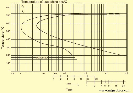
Fig 2 Isothermal transformation diagram
In addition to the curves stated above, IT diagram frequently contains intermediate curves corresponding to certain values of the transformed volume, say 20 %, 50 %, or 80 %. A decrease in the transformation rate causes displacement of the transformation start and finish curves to the right, i.e., toward greater duration. This phenomenon can be seen if the quenching heating temperature increases as a result of a decrease in the number of inclusions and growth of austenite grains. An increase in the transformation rate leads to displacement of the curves to the left. This phenomenon can be accounted for (i) by a decrease in the quenching heating temperature, (ii) the presence of carbides or inclusions, and (iii) refinement of the austenite grain. For a specified sample of steel the temperature which corresponds to a maxi mum transformation rate (the nose of the sigmoid curve) does not, as a rule, change significantly.
Continuous cooling transformation diagrams
Continuous cooling transformation (CCT) diagrams consider the transformation kinetics of eutectoid steel. The major transformation which takes place during annealing cooling of steel is a eutectoid precipitation of austenite into a mixture of ferrite and carbide. The eutectoid transformation kinetics is given by IT diagrams of austenite at a temperature of 727 deg C. The structure attained after tempering below 300 deg C is called tempered martensite. An acicular structure is seen after tempering at 300 deg C to 450 deg C. Tempering over the temperature interval of 450 deg C to 600 deg C shows a distinct dot structure. Austenite is in a thermodynamically stable equilibrium with the ferrite-Fe3C mixture. Stability of undercooled austenite is defined by a period of time during which the appearance of precipitation products in the diagram cannot be registered by conventional methods. The degree of austenite undercooling is the main factor which determines the steel microstructure. The necessary degree of undercooling is provided by either continuous cooling or isothermal treatment.
As seen earlier, in hypo-eutectoid steels the formation of pearlite is preceded by precipitation of hypo-eutectoid ferrite. With a decrease in the transformation temperature and an increase in the degree of undercooling, precipitation of hypo-eutectoid ferrite is suppressed. The amount of pearlite increases and the C content becomes less than that in pearlite of the eutectoid steel. In the region of the maximum transformation rate, the two curves merge. Thus, a purely pearlitic structure is formed in steel with 0.4 % C. In steels containing higher amounts of C, the precipitation of ferrite cannot be suppressed even if the C content decreases. Ferrite precipitation precedes the formation of pearlite even at a maximum transformation rate, but the amount of ferrite is less than that is formed at smaller undercooling.
These propositions are valid for the precipitation of cementite in hyper-eutectoid steels, but it can be suppressed even at relatively small undercooling. In this case, the C content of pearlite becomes higher than that in the eutectoid steel. As a result of suppression of the hypo-eutectoid ferrite precipitation under continuous cooling from the region of the gamma solid solution, the point Ar3 lowers much faster than the point Ar1 as the cooling rate is increased. With a certain cooling rate, both points merge into one point, which corresponds to the formation of a fine plate structure of the pearlite type free of ferrite.
Under continuous cooling the transformation process can also be visualized as diagram in temperature-time coordinates. Therefore the behaviour of cooling curves is to be analyzed to find characteristics of the transformation processes. In this diagram, the ferrite and pearlite start lines are shifted toward longer periods of time compared to the IT diagram. This is due to an increase in the temperature interval necessary for preparing the transformation processes in the austenite lattice. As a result, only part of the incubation period, which is needed for the IT to start, is effective. In this case, the incubation period is the mean of the effective lengths of time corresponding to different periods of time in the given range. This proposition can be used to calculate the behaviour of the transformation start line in the pearlite range from the IT diagram. The reverse calculation is also possible.
Similar to the pearlite range, in the bainite temperature range, the precipitation of undercooled austenite starts after a certain incubation period. Resemblance of the bainite and pearlite transformation kinetics consists not only in the presence of an incubation period but also in the character of the volume increase during isothermal soaking which is the fraction of the transformed volume of austenite increases first with acceleration and then with deceleration. At the same time, as in the case of the martensite transformation, retained austenite does not disappear completely during the bainite transformation. Every point in the bainite finish curve corresponds to certain amount of retained austenite. Similar to the pearlite transformation, the bainite transformation can take place both during isothermal soaking and under continuous cooling. Austenite which has not been transformed over the bainite range turns partially into martensite when the steel is cooled to room temperature. Since the austenite is inhomogeneous with respect to the C content after the bainite transformation, martensite is formed predominantly in C enriched regions.
For the high alloy steel, IT curves can be separated by a temperature interval in which undercooled austenite is highly stable. In this interval, pearlite precipitation does not take place for many hours, while undercooling is inadequate for the bainite transformation. In C steel, the bainite transformation proceeds concurrently with the pearlite transformation. Products of the pearlite transformation dominate at higher temperatures, and those of the bainite transformation at lower temperatures.
During the transformations of austenite on cooling in the martensite range, martensite component in the steel structure appears when the cooling rate achieves a certain value. The minimum cooling rate at which the martensite component is formed is called the lower critical rate of cooling. The rate at which transformations by the pearlite and bainite mechanisms are suppressed completely is referred to as the upper critical rate of cooling (quenching). If the conditions of austenite formation (austenitization temperature and the holding time at this temperature) and the cooling conditions (cooling rate exceeds the upper critical rate) are constant, the location of the martensite start point Ms depends only on the contents of C and alloying elements in the steel.
If the cooling rate is high, the formation rate of separate needles of martensite is also high, and transformation of austenite to martensite begins on reaching Ms-temperature. It continues on subsequent cooling to lower temperatures. As the temperature of the quenching medium is lowered, the amount of formed martensite increases first quickly and then slowly. With an increase in the quenching heating temperature (austenitization temperature), the transformation also shifts toward lower temperatures as more of the alloying elements are taken into solution. A certain amount of martensite can be formed during isothermal holding, but it is not high in C steels. Retained austenite is stabilized during isothermal holding. As a result, more martensite is formed during subsequent cooling. Formation of martensite stops at the point Mf. There is a relationship between some factors which influence the stabilization of martensite. The effect of stabilization increases with the amount of martensite in the structure or, the amount of martensite being equal, with temperature.
There is a close link between the CCT and IT diagrams. When resolving practical issues involved in heat treatment of steel, it is sometimes necessary to know how the continuous cooling rate affects the structure formed as a result of austenite transformation. For this, there have been efforts to establish the relationship between the transformation kinetics of austenite under isothermal conditions and under continuous cooling conditions. The efforts have started from the concept of additivity of the transformation processes at different temperatures. It has been presumed that holding of undercooled austenite at a preset temperature is part of the incubation period. However, it has been found, that calculated and experimental data coincide satisfactorily only if the pearlite transformation is continuous.
If the pearlite transformation is preceded by precipitation of eutectoid pearlite or the pearlite and bainite transformations occur concurrently, calculated data are at a discrepancy with the experimental data. It has been found that the discrepancy is due to the factors namely (i) holding of austenite during the time accounting for fractions of the incubation period causes acceleration of the subsequent intermediate transformation at the expense of preparatory processes, (ii) precipitation of hypo-eutectoid ferrite alters the austenite composition which delays the subsequent intermediate transformation, (iii) partial transformation of austenite over the intermediate range reduces the rate of the said trans formation at lower temperatures and facilitates an increase in retained austenite which is due to a redistribution of C and enrichment of the non-transformed part of austenite in carbon, and (iv) a change in the cooling rate over the martensite range affects stabilization of austenite in different ways.
For the above reason, special methods of constructing thermo-kinetic transformation diagrams of austenite subject to continuous cooling have been elaborated for non-eutectoid steels. From these diagrams it is possible to determine the critical rate of quenching cooling or continuous cooling which is necessary to complete a particular stage of austenite precipitation.
It has been seen that the CCT diagram is a function of the bar diameter. When steel is subjected to martensitic hardening, it is required to be cooled from the quenching temperature so that on undercooling to a temperature below the Ms point austenite has no time to precipitate and form a ferrite-carbide mixture. For achieving this, the cooling rate is to be less than the critical value. The critical cooling rate is the minimum rate at which austenite does not precipitate to a ferrite-carbide mixture. Of course, the cooling rate of steel products is non-uniform over their cross section. It can be higher than the critical rate on the surface and lower than the critical rate at the centre.
The critical cooling rate at different points of a product can be directly determined from an IT diagram. In the first approximation, it is given by the slope of the tangent to the C curve which denotes the austenite precipitation onset. This method gives a value which is around 1.5 times the true critical rate. The cooling rate can be determined more accurately if thermo-kinetic diagrams are used. Intercepts of the cooling curves with the lines of the thermo-kinetic diagrams show the start and finish temperatures of the corresponding transformation.
From the transformation diagram, it is possible to determine, for example, the rate which provides 40 % martensite in the structure or the rates at which the entire transformation occurs in the pearlite range, i.e., hardening is omitted altogether. Because the data on the critical hardening rate depend on cooling time and is to be associated with a specific temperature (at which direct measurements of the hardening rate are practically impossible), it is proper to specify the cooling time for a specific interval of temperature, for example, from the point A3 to 500 deg C. Point A3 in the diagram is the time reference. Then it is possible to directly determine the critical cooling time K (Km for fully martensitic hardening, Kf for initial appearance of ferrite, and Kp for full transformation in the pearlite range).
Since the cooling time and the progress of the subsequent cooling of the sample during end-face hardening are known, the outcome of hardening can be determined from the transformation diagram. It is to be remembered that a transformation diagram is valid only for particular conditions of melting and homogenization. Deviations in the composition or grain dimensions cause changes in the trend of thermodynamic curves. This is explained by the fact that an increase in the homogenization temperature and time and, consequently, enlargement of the grains enhance the stability of austenite. Conversely, refinement of grains lowers the critical cooling rate, since stability of austenite decreases with an increase in the extent of grain boundaries.
Hardenability
The depth of the hardened zone is termed hardenability. This is one of the most important characteristics of steel. Since the cooling rate is non-uniform along the cross section of a sample, austenite can pass into martensite in surface layers only, while at the centre of the sample austenite undergoes the pearlite transformation. In the first place, hardenability depends on the critical cooling rate. An examination of the temperature curves plotted for different areas of the sample shows that the cooling rate of the core of a large diameter product is lower than the critical value and hence the core is not martensitically hardened. Martensite is present in the surface layer only.
After hardening treatment, a bulky part with a large cross section can show the entire range of structures such as a smooth transition from martensite near the surface through troostite-martensite and troostite to pearlite at the centre. The geometry of samples can influence the character of the cooling curves. However, given the same surface-to-volume ratio, the curves coincide in general. The highest changes in the cooling rate are experienced by the diameter of samples.
Considering the above, for achieving a through hardening of bulky products or full martensitic hardening to the core of a product, it is essential to provide the critical hardening rate along the entire cross section of the product. IT and CCT diagrams can be used to determine this rate. The diagrams are usually plotted for different grades of steel, taking into account the progress of cooling in different sections and in different hardening media.
The hardenability of steels depends on the steel composition, specifically on the C content. In the steel hardenability diagrams, the hardenability of each grade of steel is normally presented as a hardenability band. These diagrams have been plotted for almost all existing grades of steel. They show how to achieve hardening of a product made of particular steel.
Hardenability of steel is also categorized by IT curves. The more the curve is shifted to the right along the X-axis, the greater is the hardenability of the steel. This is explained by the fact that the rightward shift of the IT curve is due to better stability of austenite.
An improvement in the stability of undercooled austenite and hence an increase in the critical hardening rate lead to a greater depth of hardening. Then hardenability depends on all the factors which improve the stability of undercooled austenite. As an example, the stability of austenite can be raised by alloying steel with chromium and tungsten. These elements lower the austenite precipitation rate and can make steel an air-hardening one. Steel with a normal content of impurities is hardened to strength ten times that of a pure Fe-C alloy.
Elevation of the hardening temperature favours an increase in the hardening depth due to the homogenization of austenite and enlargement of austenite grains. Refinement of grains impairs hardenability as grain boundaries affect the stability of austenite. The hardening depth also depends on the hardening medium used. The greater is the intensity of cooling, the greater is the depth of hardening. Besides, the hardening depth depends on the cross-sectional diameter of the products. The critical diameter is that of the greatest cross section which lends itself to through hardening in a given hardening medium. The critical diameter is different for different hardening media and characterizes the hardenability provided by a particular method only.
Hardenability has an effect on the mechanical properties of steel. In the case of through hardening, the properties do not differ along the cross section of a product. Otherwise they decrease from the surface to the centre. The analysis of the influence of hardenability on the properties of steels which have been tempered after hardening shows that a high temperature favours equalization of hardness along the cross section. However, the structure of weakly hardenable steels remains inhomogeneous. This is due to a grain structure appearing on the surface, where martensite is formed during quenching, while a lamellar structure remains at the centre. A grain structure is present along the entire cross section of through-hardening steel. This determines the character of changes in the properties of steels with different hardenability. The properties which are independent of the Fe3C form (YS, specific elongation, impact strength) differ.
The properties of tempered steels (fracture stress, YS, impact strength, reduction in area) are impaired if ferrite precipitates during quenching. The mechanical properties of a product depend on its cross-sectional area. To obtain the best mechanical properties in the tempered state, a grain structure is required to be provided along the entire cross section; i.e., through hardenability is to be ensured in the quenched state.
Grain size
It is necessary to know the material structure while analyzing any processes or properties associated with grain boundaries. Most of the steel materials have polycrystalline structure and they comprise a set of grains separated by boundaries. The grain boundary is one of the basic structural elements in polycrystalline steel materials. The grain boundary represents an interface between two differently oriented crystals. This is the region of crystal imperfection. It is capable of moving and adsorbing impurities. The boundary has a high diffusive permeability.
In polycrystalline steel materials, the boundaries determine the kinetics of many processes. For example, movement of grain boundaries controls the process of recrystallization. A high diffusive permeability of grain boundaries determines the kinetics of diffusion-dependent processes at moderate temperatures. Embrittlement of steel material is connected with enrichment of grain boundaries in impurities.
Grain boundaries are normally divided into two large groups namely (i) low angle boundaries, and (ii) large angle boundaries. Low angle boundaries are sub-grain boundaries with an angle of less than 10 degrees. They represent networks or walls of dislocations. The structure of large angle boundaries is much more complicated. The progress in understanding the structure of grain boundaries is connected with elaboration of the models describing the observed microscopic properties of the boundaries.
Grain size determination
The size of the grain that is formed under a given treatment is determined from micro-sections after their etching. For C and alloyed steels the reagent used is 1ml to 5 ml HNO3 +100 ml ethyl or methyl alcohol. Austenitic steel is etched in a copper sulphate-chloride solution containing 10 grams copper sulphate, 50 ml hydrochloric acid, and 50 ml water. When C and low alloy steels are etched, the reagents turn pearlite dark and make visible the ferrite grain boundaries, the martensite structure, and tempering products. The etching rate rises with the amount of nitric acid. The etching time is from several seconds to a minute. Etching of austenitic steel reveals the austenite structure and the austenite grain boundaries.
Carburization is also used to establish the austenite grain boundaries. In this case, samples are heated to 930 deg C in a carburizing medium (e.g., a mixture of 40 % BaCO3 and 60 % charcoal), cooled, and etched.
In addition, an oxidation method is used according to which micro-sections are heated in vacuum to a temperature 20 deg C to 30 deg C higher than the quenching temperature and are soaked for 3 hours. Subsequently air is fed to the furnace for 30seconds to 60 seconds, and the samples are cooled in water. Before quenching it is desired to heat samples in borax melt at 930 deg C to 950 deg C for 30 seconds to 40 seconds and then cool them in water. After these treatments micro-sections are polished and etched in a 15 % solution of hydrochloric acid in ethyl alcohol. Grain boundaries are seen as the oxide network.
Apart from this, use is made of the method of etching austenite grain boundaries, the method of the network of ferrite (for steels with a C content of up to 0.6 %) or Fe3C (for hypereutectoid steels), and the method of the pearlite network for steels which are closer in composition to eutectoid steels.
The grain size is determined by comparing the observed microstructure at a 100x magnification with standard scales (the scales are elaborated so that at a magnification of 100x the grain number N corresponds to the formula ‘n =8 X 2 to the power n’, with n the number of grains per sq mm of the micro-section area) or by counting the number of grains per unit area of the micro-section, or by calculating the mean nominal diameter of the grains or their number per cubic millimeter.
The austenite grain boundary structure which is produced on heating above the critical points is important since the austenite transformation products formed during cooling (martensite and pearlite etc.) appear inside austenite crystals. A coarse austenite grain determines a coarse plate structure of martensite during quenching or a coarse cellular network of ferrite (cementite) precipitates at the boundary of the initial austenite grains during annealing or normalization. The pearlite structure is also the coarser and the larger is the pearlite grain.
As is known, a coarse grain structure of steel (ferrite-pearlite, martensite, etc.) is characterized by lower mechanical properties. For this reason a fine-grain structure of steel is desirable in practice.
Grain size refinement
It is possible to refine a coarse-grained structure and this is widely used in the heat treatment of steel. The grain refinement, which takes place on heating steels above the Ac3 temperature, is related to a transition to the austenite state through nucleation of numerous centres of the austenite phase. Development of these centres leads to formation of a relatively fine grained structure. Above Ac3 temperature, the cross sectional size of the grain is 10 mm -30 mm. Initially the grain size is independent of the grain of the starting structure. It can be very fine irrespective of whether the starting structure of the steel is fine or coarse. A fine grain structure of the restored austenite provides a fine grain structure of cooled steel irrespective of the structural components (pearlite, bainite, or martensite) which are formed. This is due to the fact that all the transformation products nucleate within each separate grain of austenite.
Excess phases (ferrite in hypo-eutectoid steel and Fe3C in hyper-eutectoid steel) precipitate at boundaries of small austenite grains, and the pearlite transformation is accompanied by the appearance of smaller pearlite colonies. Fine austenite grains determine the formation of fine-needle martensite. This underlies the grain refinement effect which is associated with heating above Ac3 temperature. Heating the steel above Ac3 temperature during full annealing, normalization, or quenching is followed by recrystallization. With an initially coarse grain structure, recrystallization results in refinement of grains at a heating temperature corresponding to Ac3 temperature.
If the heating temperature is much higher than Ac3 temperature, then the grain is enlarged again, and the expected correction of the structure during the gamma to alpha transformation does not take place. Refinement of crystallites is especially pronounced when transformation to the austenite state starts in many centres inside the initial structure. The formed centres are to have a random orientation, which is not connected with the orientation of the alpha phase in the initial structure. Normally such centres are sufficiently large in number so that the grain size does not exceed 15 mm to 30 mm. During pearlite precipitation of austenite, breaking of an austenite grain into pearlite colonies, each of which can be considered an independent grain, also represents refinement of steel.
Strengthening mechanism in steel
There are four strengthening mechanisms in steel namely (i) solid solution strengthening, (ii) grain size refinement, (iii) dispersion strengthening, and (iv) work hardening.
Solid solution strengthening is a phenomenon which occurs when the number of impurity atoms in the lattice of the basic element is so small that they are incapable of forming both stable and metastable precipitation phases under any heat treatment conditions. However the impurity atoms favour improvement of the mechanical properties. The presence of impurity atoms in the matrix lattice leads to distortion of the lattice because of the difference in size between the atomic radii of the impurity and the basic component. This in turn leads to the appearance of elastic deformation fields, which retard movement of dislocations in slip planes under the action of applied stresses. In addition, the impurity atoms can obstruct movement of dislocations by forming impurity atmospheres around them. Both of the above factors play a leading role in solid solution strengthening.
Carbon which is statistically uniformly distributed in the lattice of the alpha iron has an influence on the structure and properties of alpha iron. Solubility of C in alpha iron is much lower than in the gamma iron. It forms interstitial solid solutions with both types of irons. However, whereas the gamma iron lattice has sufficiently large pores for implantation of C atoms, the cubic lattice of the alpha iron suffers. Upon introduction of C atoms, a tetragonal distortion takes place which is similar to the one of the martensite lattice except that in the former case the distortion is much smaller. In addition, inserting of C atoms causes the entire lattice of the alpha iron to somewhat expand. Hence, C affects the properties of the alpha phase. Actually, there is a dependence of the YS on the C concentration in the solid alpha solution. The influence which C exerts on plastic deformation resistance of the alpha phase is due to its strong interaction with dislocations as well as pinning of the dislocations and elastic deformations arising as a result of the tetragonal distortion of the alpha phase lattice after insertion of C atoms.
The presence of C in lattices of different structural components formed during thermal treatment of steel also leads to changes in their mechanical properties. As an example, the location of inserted C atoms primarily in one of the sub-lattices of interstitial sites during the martensite formation brings about additional tetragonal distortions of the martensite crystal lattice. This enhances plastic deformation resistance owing to the interaction between the stress fields around C atoms and those at dislocations. The influence of C dissolved in the alpha phase on the mechanical properties of steel is also witnessed in the case of the ferrite – pearlite transformation. The dissolution of part of the C in the alpha phase suggests that the solid solution strengthening of the phase is one of the factors providing the high strength properties of intermediate transformation products.
Grain size refinement of steel has a strengthening effect on steel. Impact strength is especially sensitive to the austenite grain size, and it decreases with grain enlargement. A decrease in the dimensions of pearlite colonies inside the initial austenite grain also favours a rise in impact strength.
Although the grain size has a considerable effect on impact strength, its influence is small if any on the individual mechanical properties such as hardness, fracture stress, YS, and specific elongation. Only the actual grain size affects steel properties, the inherited size has no effect. However, the technological process of heat treatment is determined by the inherited grain.
In the steels, precipitation of supersaturated solid solutions formed during quenching is followed by precipitation of disperse particles enriched in atoms of the alloying components. The strength (hardness) of the steels increases with the precipitation of these particles. The increment in the value of these characteristics increases as the dispersion and volume fraction of the particles increase. This phenomenon has been referred to as dispersion strengthening.
Precipitation of supersaturated solid solutions takes place during the heating (aging) of quenched steels. The strengthening is due to an increase in resistance to the movement of dislocations in a crystal when obstacles (barriers) of any type are formed. In aging steels, dislocations meet regions which retard their movement. The character of interaction between moving dislocations and precipitates of the second phase can be different depending on the phase morphology and structure. The total effect of aging on the strength properties of steels is determined by (i) the strength of the precipitates formed, (ii) the volume fraction of precipitates, (iii) the degree of precipitate dispersion, (iv) morphology, structure, and type of binding with the matrix, and (v) temperature.
When a solid solution of C in alpha Fe is cooled below A1 temperature, C precipitates as Fe3C with lowering of the C solubility and a decrease in temperature. This process takes place under sufficiently slow cooling, which is accompanied by diffusion processes, leading to the formation of cementite. In the case of abrupt cooling (water quenching) C has no time to precipitate. A super-saturated alpha solid solution appears. During subsequent storage at room temperature (natural aging) C tends to precipitate from the solid solution. Carbon enriched regions appear primarily in defective sections of the matrix. Precipitation of C from a supersaturated solid solution during natural aging results in an improvement of its strength properties and hardness. However, plastic properties such as reduction in area, specific elongation, and impact strength are deteriorated and the phenomenon of dispersion strengthening is seen.
As the heating temperature is increased (artificial aging), dispersion strengthening accelerates. This is due to the intensification of diffusion processes with an increase in temperature. The total process of C precipitation from the super-saturated solid solution in alpha Fe comprises several successive processes. Mechanical properties and hardness are not sensitive to structural changes which take place during the aging of the steels. Sharp changes in properties indicate alterations in the structural state of the steel.
A maximum change in mechanical properties during precipitation is achieved only if excess crystals in a highly disperse state precipitate. Subsequent coagulation of the crystals leads to degradation of the properties.
The influence of different solubilities of C in alpha Fe on the properties of the steel (dispersion strengthening) during low temperature aging is prominent in low C steels. In steels containing C higher than 0.4 %, the above effects are not noticed due to the influence of Fe3C particles formed during the pearlite transformation. Besides, nucleation of the precipitating phase can be inhibited owing to migration of C to the Fe3C-ferrite interfaces. As a result, the amount of C concentration at lattice defects decreases.
Cold plastic deformation greatly accelerates precipitation of a supersaturated solid solution. This is due to an increase in the density of dislocations, which are preferable sites of heterogeneous nucleation of precipitates as well as to an increase in the concentration of vacancies, which facilitates the diffusion of C to clusters. Mechanical properties change during aging after cold working in the same way as after quenching, that is, the YS, the fracture stress, and hardness are altered. With an increase in aging time, specific elongation and reduction in area decrease and the tendency to brittle fracture is enhanced. The rate of change is higher than in quenched steel. Also, the nature of the changes is different. Whereas in the case of aging after quenching, hardness reaches a maximum and then drops, after cold working hardness does not decrease with the aging time. As the aging temperature is raised, the maximum hardness of quenched steel lowers, while after cold working hardness is independent of the aging temperature. This is explained by the fact that a considerable amount of C is concentrated near dislocations. Few, if any, clusters nucleate in the matrix homogeneously. Consequently, clusters cannot grow at the expense of other clusters, i.e., they cannot coagulate.
An important method used to strengthen steels is deformation strengthening. Strengthening achieved with crystal deformation can be judged from the shape of stress-strain curves. The actual shape of these curves largely depends on the crystal lattice type of the metal, its purity, and thermal treatment.
In the case of cubic lattice steels, strengthening curves are parabolic, whereas for hexagonal lattice metals a nearly linear dependence is observed between the stress and the strain. This fact suggests that plastic deformation strengthening is determined mainly by the interaction of dislocations and is associated with the structural changes which retard the movement of dislocations. Metals with a hexagonal lattice are less prone to deformation strengthening than cubic lattice steels because the hexagonal lattice has fewer easy slip systems. In cubic lattice steels, the slip proceeds in several intersecting planes and directions.
There are three stages during the work hardening. The first stage is due to the easy slip. It depends on the orientation of the crystal relative to external forces and on the presence of impurities. This stage is characterized by a linear dependence of strain stresses on the strain at a small work hardening rate. Dislocations usually slip in primary systems.
In the second stage the work hardening rate is much higher than the first stage. Dislocations move in intersecting slip planes and, on colliding, form additional obstacles to their movement. This state is most extensive in the stress-strain curve. The ratio between the work hardening rate and the shear modulus (or any other elastic constant) is almost independent of the applied stress and temperature. It depends little on the crystal orientation and presence of impurities.
In the third stage changes are possible in the distribution of dislocations. They can either get around obstacles which retard their movement at the second stage or interact with dislocations. As a result, the work hardening rate is lower compared to which is observed during the second stage. At this stage, a partial relaxation of stresses can occur owing to the appearance of the secondary slip system. The reduction of distortion can have the result that deformation continues in the primary system, which gets rid of a certain number of dislocations passing to the system. A characteristic feature of deformation in the third stage is the development of a cross-slip representing the main mechanism by which dislocations bypass the obstacles formed in the second stage.
Heat treatment processes for steels
There are three basic processes for the heat treatment of steels. These are (i) annealing, (ii) quenching, and (iii) tempering.
Annealing
Annealing process of steels has different methods namely (i) diffusion annealing, (ii) softening, (iii) phase recrystallization annealing or full annealing (normalization, high temperature or coarse grain annealing, and pearlitization), and (iv) stress relief annealing and recrystallization annealing.
The objective of diffusion annealing is to eliminate, as far as possible, in-homogeneities in the chemical composition, in particular liquation in-homogeneities, which occur during crystallization of steels. This annealing is usually carried out in the range of the gamma solid solution at a temperature of 1100 deg C to 1300 deg C. Diffusion annealing can be used primarily to smoothen out a difference in the content of alloying elements, the difference being due to the inter-crystal liquation. This shows up as smearing of dendrites with an increase in temperature and heating time. Differences in micro-hardness are removed simultaneously. The overall hardness of the steel decreases since liquation regions possessing high hardness is removed. Some average hardness is attained. The success of diffusion annealing largely depends on the steel purity and liquation. This type of annealing is generally used to improve properties of medium purity steels.
Softening is used to produce the structure of globular pearlite. This structure is very soft and readily lends itself to deformation during drawing and cold rolling etc. Steels with a low C content become too soft after this annealing treatment. The globular pearlite structure is favourable in steels with a C concentration of more than 0.5 %. Another goal of softening is to produce a uniform fine structure with finely dispersed C after quenching. The simplest method of softening consists in holding for many hours at a temperature slightly above Ac1 temperature. In this case, martensite which is left from the previous treatment is removed and the work hardening caused by cold working is eliminated. Cooling after softening can be done in air starting from 600 deg C. Refinement of the structure subjected to softening is achieved only above the point A1 temperature.
Phase recrystallization annealing consists of a twofold gamma to alpha transformation, which takes place during this annealing. It leads to the appearance of a fine grained uniform structure differing completely from the initial structure. Refinement of the grain during normalization results in the disappearance of the Widmanstätten and coarse grained cast structures, which have poor mechanical properties. Inhomogeneity of the structure in the work hardened state is removed. The closer the annealing temperature is to Ac3 temperature and the shorter the holding time at this temperature, the finer is the grain. Refinement of the grain structure is also facilitated if the heating rate to the annealing temperature and the cooling rate from this temperature are increased.
In the case of normalization, cooling is done in air. Here it is important to allow for different rates of cooling along the cross section of large sized products. The arising thermal stresses are removed by stress relief annealing or high temperature tempering. To obtain a fine grained structure, rapid cooling is done only over the transformation temperature interval. The normalization heating temperature is not to be much higher than the transformation point, or else the grain may be too coarse (overheating). An excessively long holding time also have the same result. The optimal heating temperature is determined by the C content.
Stress relief annealing and recrystallization annealing removes macroscopic stresses which are present in cold worked steels due to the dislocation pile ups and crystal lattice distortions. Normally these stresses are very high. Changes in properties which occur during the cold working can be rectified during subsequent heating. The greater is the degree of cold working, the lower is the heating temperature. Depending on the temperature and time of annealing, various structural changes take place in a cold worked material. The changes are divided into recovery and recrystallization processes.
Recovery is a totality of any spontaneous process of variation in the density and distribution of defects before the onset of recrystallization. If recovery proceeds without the formation and migration of sub-grain boundaries inside the recrystallized grains, it is called restoring. If sub-grain boundaries are formed and migrate inside the crystallites, recovery is referred to as polygonization.
Restoring does not include an incubation period. Properties start changing right at the beginning of annealing. Restoring is accompanied by a redistribution of point defects whose concentration decreases subsequently from excess concentration to the equilibrium concentration. Simultaneously, dislocations are redistributed and unlike-sign dislocations are annihilated.
The structure of steel starts changing drastically from a certain annealing temperature. New rather equilibrium grains are seen along with extended cold worked grains. They differ from the grains of the deformed matrix by having a more perfect internal structure. As distinct from the polygonized structure, recrystallized grains are separated from the matrix with large angle boundaries.
The formation and growth of grains with a more perfect structure which are surrounded by large angle boundaries at the expense of initially cold worked grains of the same phase is called primary recrystallization. Recrystallization begins with an incubation period. The recrystallization rate increases initially from zero to a maximum and then decreases due to an ever rising number of new grains in contact with one another.
Inclusions of insoluble impurities (carbides, nitrides) lower the tendency to growth of recrystallized grains. This is especially important in the case of ferritic steels, which are prone to grain growth. Another phase can precipitate during recrystallization in alloy steels which are subjected to a strong cold working.
Sometimes the intensive growth of individual crystals can be seen after a strong deformation and long holding (for several days) at temperatures close to the melting point. This phenomenon is called secondary or collective recrystallization.
Quenching
Quenching is the strengthening treatment. It consists of cooling from the temperature range of the solid solution at such a rate that transformation in the primary and bainite ranges are suppressed and martensite is formed. In this state, steel has the property of the highest hardness. There is a distinction between (i) normal quenching, which is used mainly for treatment of medium C and high C steels, and (ii) quenching after a thermo-chemical treatment (carburization, high temperature cyaniding etc.), which is used for low C steels.
In case of normal quenching for providing a required cooling rate during quenching, different cooling media and methods are used. Water, oil, or air can serve as the cooling medium. Many alloy steels, which have a high stability of austenite, are subjected to step quenching. With this method of quenching, the temperature drop is less than in the case of direct cooling to room temperature and consequently quenching stresses are less.
Some quantity of austenite is retained during quenching even in steels with a relatively small C content. For this reason it is impossible to impart the maximum hardness to a product. Since austenite is stable at room temperature and passes to martensite at lower temperatures, steels are being given a subzero treatment. Under this treatment quenching is continued and steels with a high content of retained austenite are immersed in liquid nitrogen (N2) or quenching mixtures whose temperature is below 0 deg C.
For surface quenching (if it is necessary to harden only the surface layer to a preset depth), special quenching heating schedules are used. The surface of the steel is fully heated, while the core is cold and remains unquenched on subsequent fast cooling. The selection of steel for surface quenching is governed by the sensitivity of the steel to quick heating and cooling. For this reason the C concentration is limited to 0.7 % to prevent cracking of the steel.
Among the quenching defects, the main defects are excessive holding and overheating. They show up as enlargement of martensite needles and coarse grain fracture. This leads to a high brittleness of quenched steel and the formation of cracks. Cracks are frequently formed at the boundaries of initial austenite grains. A low quenching temperature or too short a holding time at the given temperature causes incomplete quenching. In this case, the quenched steel is insufficiently hard.
Carburization is the thermo-chemical treatment which is associated with surface saturation of steel with C and N2. These elements quickly dissolve in Fe by the interstitial method and are capable of rapid diffusion to a considerable depth. Low C steels are subject to carburization. Carburization is usually carried out at 900 deg C to 950 deg C. Gas carburization is used mostly, under which steel is heated in the atmosphere generated from a gas which contains predominantly methane (CH4) or from liquid hydrocarbons (kerosene and gasoline etc.). Carburization is aimed at enrichment of the surface layer with carbon. The required strengthening of the surface layer is achieved by quenching, which is done after the carburization. The specific volume of the quenched carburized layer is higher than the specific volume of the core, and hence considerable compression stresses arise in the layer. This improves the fatigue strength of the steels.
Cyaniding consists of the saturation of the surface of steels with C and N2 in a cyanide-containing salt bath. The C-N2 ratio in the diffusion layer is controlled by changing the medium’s composition and the processing temperature. Advantages of cyaniding over carburization consist in a shorter processing time and improvement in the wear and corrosion resistance (owing to the presence of N2 in the surface layer).
Tempering
The main purpose of tempering is to provide a disperse structure at a preset degree of cooling. In the case of low C steels, quenching serves as tempering even if the steel is not subjected to high temperature tempering it has a high viscosity and a relatively high strength.
When some of the steels are quenched in oil, a structure is formed even during transformation in the bainite range which is more disperse than the one formed after cooling in air. But the most disperse distribution of carbides and the most favorable properties are obtained after martensite tempering. The structure dispersion has the highest effect on the YS. An improvement of the fracture stress and YS and an increase in the fracture stress -YS ratio can be taken as a measure of the tempering efficiency. The tempering efficiency depends on the cross-sectional area and on the content of C and alloying elements in the steels.
Although to achieve a thorough quenching the critical quenching rate has to be exceeded over the entire cross section, full tempering does not require this procedure. As an example, in quenched steel which has martensite in the surface zone and pearlite in the core, the hardness of the core can sometimes be higher than that of the surface zone after tempering. This is particularly the case during a short tempering when precipitation of carbides from martensite proceeds faster than the coagulation of pearlite plates.
Tempering of hypo-eutectoid steels which do not contain free ferrite gives a uniform improved structure. In the presence of ferrite precipitates, the fracture stress-YS ratio decreases and the impact strength is lesser than in the surface zone. Hence, in selecting the content of C and alloying elements and particular conditions of austenitization and cooling, the size of the steel product to be tempered is required to be considered. For tempering to give adequate properties, it is often enough to suppress the formation of ferrite during continuous cooling. Only when a very high fracture stress is required an abrupt cooling is used for tempering. In this case, susceptibility to full tempering can be improved by raising the quenching temperature and thus enlarging the austenitic grain size.
Processus de fabrication
- Traitement thermique des pièces usinées avec précision
- Avantages du traitement thermique sous vide dans les poinçons et les matrices
- L'importance d'un traitement thermique efficace pour les poinçons, les matrices, les lames et les aciers à outils
- Les principes d'un poinçonnage réussi
- Les principes fondamentaux de la rectification plane
- L'eau chaude parfaite de la pompe à chaleur
- Comprendre la mise en solution, le recuit, la nitruration
- Processus de traitement thermique de l'acier
- 3 étapes du processus de traitement thermique