Jukebox moderne
Composants et fournitures
 |
| × | 1 | |||
| × | 1 | ||||
 |
| × | 1 | |||
 |
| × | 1 | |||
| × | 1 | ||||
| × | 1 | ||||
| × | 1 | ||||
| × | 1 | ||||
| × | 1 | ||||
 |
| × | 1 | |||
| × | 1 | ||||
 |
| × | 2 | |||
 |
| × | 1 | |||
| × | 2 | ||||
| × | 1 | ||||
| × | 1 | ||||
| × | 1 | ||||
| × | 1 | ||||
 |
| × | 1 | |||
| × | 4 | ||||
| × | 8 | ||||
 |
| × | 4 | |||
| × | 1 | ||||
| × | 1 | ||||
| × | 1 | ||||
| × | 1 | ||||
| × | 1 | ||||
| × | 1 | ||||
| × | 1 | ||||
 |
| × | 12 | |||
| × | 1 | ||||
| × | 1 | ||||
| × | 1 | ||||
| × | 1 | ||||
 |
| × | 7 |
Outils et machines nécessaires
 |
| |||
 |
| |||
 |
| |||
|
Applications et services en ligne
| ||||
 |
| |||
|
À propos de ce projet
Mise à jour :comme vu dans le magazine MagPi, numéro 105
Inspiration
Je suis amoureux des jukebox classiques depuis des années. Dès 2014, j'essayais d'en faire un, mais je n'avais pas les compétences pour une belle construction. Avance rapide jusqu'à aujourd'hui, où j'ai acquis des compétences en impression 3D et en conception.
La passion, la curiosité et le désir ont conduit cet effort. Si vous pensez que vous aimeriez avoir un mini jukebox comme celui-ci, il existe des offres grand public qui sont beaucoup moins cher, comme ce modèle de table Victrola pour 65 $ USD. Le fabricant de hacksters Flyingangel a une excellente construction de jukebox. D'un autre côté, il existe des juke-box modernes prêts à l'emploi qui sont plus grands (105 cm / 41,3 in H) mais beaucoup plus chers à environ 795 $ US. Vérifiez le Coût et Effort sections ci-dessous pour voir combien est impliqué dans ce projet.
Attribution
Ce projet n'aurait pas été possible sans l'excellente conception de jukebox 3D de Marco Gregorio sur grabcad. C'est un travail magnifiquement détaillé, d'autant plus étonnant que Marco n'avait pas de juke-box physique à partir duquel modéliser, juste ce qu'il pouvait trouver sur Internet ! Tu te dois d'aller voir le travail de Marco...
Le code Arduino utilisé pour allumer les LED au son de la musique est également essentiel au jukebox, par Michael Bartlett sur learn.sparkfun.com.
Présentation
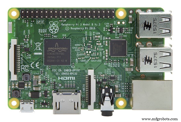
Il s'agit d'un lecteur de musique alimenté par le logiciel gratuit Volumio. Volumio comprend AirPlay, Spotify, Pandora, la radio Web et votre propre musique contrôlée depuis votre ordinateur, tablette ou téléphone - il suffit de télécharger et d'installer. Qu'est-ce que j'ai ajouté ? Un boîtier 3D, un écran LCD tactile et des LED qui s'illuminent au rythme de la musique. L'écran LCD est alimenté par un Raspberry Pi 3 ou 4. Les LED sont contrôlées par un Arduino Micro sur une carte Adafruit Perma-Proto fixée au sommet d'une pile matérielle :Raspberry Pi et IQAudio Pi Digi Amp.
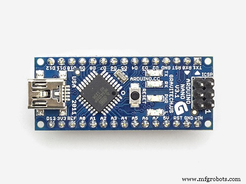
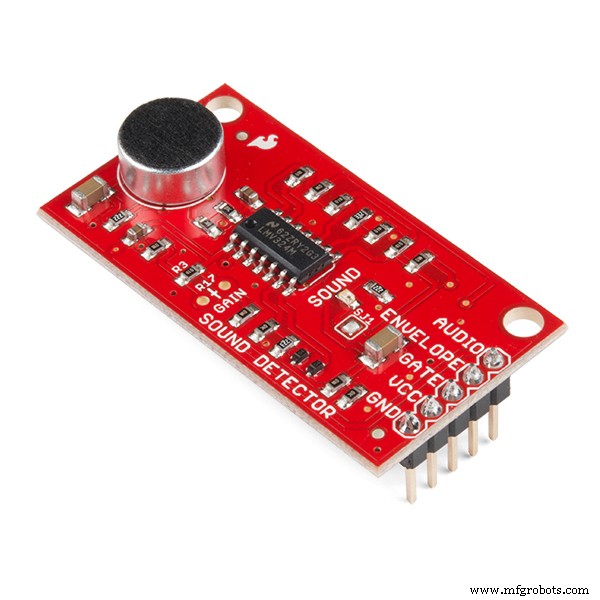
J'utilise du vieux matériel, la carte d'ampli IQAudio et un Arduino Micro, que j'avais en inventaire. Au moment d'écrire ces lignes, IQAudio fait maintenant partie de Raspberry Pi, et le Pi Digi Amp Plus est toujours disponible, ET pour moins que ce que j'ai payé pour cela. L'Arduino Micro est obsolète, mais vous pouvez utiliser un Arduino Nano ou Adafruit Itsy-Bitsy. Vous devrez effectuer des ajustements pour l'utilisation des broches analogiques et numériques et alimenter en 5 V du Digi Amp vers la carte fille (Arduino). Enfin, un détecteur de son Sparkfun transforme comme par magie le son en bits numériques.
Marco a fourni un fichier STEP pour tous les composants du jukebox que j'ai pu importer dans l'application de conception 3D Fusion 360. Ce que j'ai fait, c'est :
- Mettre à l'échelle le modèle à 25 % de la taille du modèle grandeur nature de Marco
- Examinez les composants du modèle et décidez ce qu'il faut conserver et ce qu'il faut ajouter
- Masqué les parties du modèle que je n'ai pas utilisées
- Ajouter et modifier des fonctionnalités pour créer un boîtier utile
- Imprimez les corps 3D qui forment l'enceinte
- Ajoutez de l'électronique pour alimenter Volumio et les LED
Objectifs de conception
- Mesurer environ 15 pouces/381 mm de haut
- Écran tactile qui affiche Lecture en cours/Art de l'album
- Haut-parleurs au son correct
- Lumières... Il devait avoir plein de jolies LED animées
- En fait RESSEMBLE il a été imprimé en 3D (pas de post-traitement de l'impression); cela signifiait imprimer dans différentes couleurs de filament
- Aucune impression 3D de plus de 12 heures environ (pas d'impression pendant la nuit)
- Masquer ou minimiser les joints des pièces
Niveau de compétence :avancé
- Plus de 75 heures de temps d'impression au total pour les pièces 3D
- Assemblage critique - vous devez faire les choses "juste", faire les choses dans un certain ordre
- Espace confiné pour travailler à l'intérieur du boîtier une fois terminé
Coût :cher
(Tous les frais sont en USD)
Au strict minimum :
- Si vous post-traitez, vous aurez besoin de 2 à 3 bobines de filament 3D blanc et de fournitures de finition, environ 70 à 90 $
OU
- Dépend de ce que vous avez. J'ai juste dû acheter une bobine de filament rouge, environ 30 $. J'imprime en 3D depuis 2017 et c'est un passe-temps important pour moi. J'avais du filament argent, blanc, marron et noir en stock. Ceux-ci, plus une bobine de rouge seraient au moins environ 100 $.
- Arduino Nano ou Adafruit Mini Metro, environ 20 $ (j'avais Arduino Micro en stock)
- Chapeau Adafruit Raspberry Pi Perma Proto 5 $
- Écran tactile HDMI (Uctronics) 5 pouces, 53 $
- Raspberry Pi 3B Plus 35 $ (en main)
- Enceintes Parts Express Dayton Audio RS100-8, 2 x 60 $ au total (en inventaire)
- Câble de haut-parleur Parts Express, 18AWG environ 20 $ (en inventaire)
- Tissu pour grille de haut-parleur Parts Express, 30 $ (en inventaire)
Comptez 40 $ supplémentaires ou plus pour les câbles/connecteurs HDMI, les commutateurs, le matériel de montage, les câbles de raccordement, l'embase femelle, etc. J'en avais beaucoup en inventaire. Pour moi, le coût actuel des débours était d'environ 150 $, étalé sur des mois, car j'avais tellement de fournitures sous la main. Si vous deviez sortir et acheter toutes ces fournitures... Eh bien, faites le calcul.
Pour moi, le coût en valait la peine.
Effort
Les impressions 3D prendront 75 heures ou plus, selon votre imprimante. Il y a 21 parties différentes avec environ 12 qui prennent plusieurs heures à imprimer. Les parties restantes prennent environ 1 à 2 heures chacune. Et cela en supposant que vous n'avez pas d'impressions à refaire.
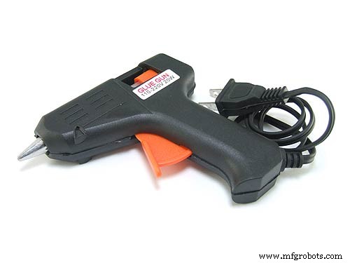
J'ai utilisé de la colle chaude pour préparer et coller les sections du boîtier ensemble, en 4 phases. Supposons 3-4 heures. pour ça. Le collage des chaînes de LED prend environ une heure pour la configuration et l'exécution. Il y a aussi un collage précis de petites pièces décoratives (avec de la colle CA) pour compléter le jukebox.
Pour l'électronique, comptez au moins 5 heures pour :
- Installer Volumio
- Installer l'esquisse Arduino
- Disposition et soudure du circuit imprimé
- Testez que tout fonctionne avant l'assemblage final !
- Montez le panneau LCD
- Montez les cartes RPi, IQAudio Digi Amp Plus et Perma Proto dans une pile
- Soudage et montage des interrupteurs et de la prise d'alimentation
- Montez les haut-parleurs et les fils des haut-parleurs
Le collage final peut prendre 1 à 2 heures.
En résumé, outre le temps nécessaire pour imprimer toutes les pièces, l'assemblage peut prendre environ 12 heures ou plus.
Téléchargements
La documentation, le code et les fichiers d'impression 3D sont disponibles sur github.
Les fichiers d'impression 3D sont également disponibles sur thingverse.
Impression 3D
Il existe au total 21 fichiers de pièces STL distincts. Certaines parties nécessiteront 2 copies/impressions.
Mise en route
Assurez-vous de lire attentivement les commentaires dans les sections « Choses ». Ils donnent les informations nécessaires sur les composants exacts à utiliser. Si vous effectuez des substitutions de pièces, vous devrez déterminer les modifications à apporter.
Pour vous assurer que tout fonctionne, testez que toute l'électronique fonctionne ensemble avant d'assembler le boîtier :
- Installer et configurer Volumio
- Souder le circuit imprimé
- Câblez les composants :NeoPixels, LED RVB à fondu lent et commutateurs
- Ajouter des composants à la carte
- Télécharger le sketch Arduino depuis github
- Télécharger le croquis sur l'Arduino, monté sur la carte
- Essayez tout
Installer Volumio
Accédez à la page de démarrage de Volumio et suivez le guide d'installation de votre Raspberry Pi. Pour commencer les tests, montez l'amplificateur numérique IQAudio Pi sur le Raspberry Pi, branchez l'amplificateur dans l'embase femelle du Pi et utilisez des entretoises entre le Pi et l'amplificateur IQAudio, comme indiqué sur la photo ci-dessous. Plus tard, reportez-vous à ce guide pour les monter dans le fond du juke-box imprimé en 3D.
_9H4kWWGtUT.jpeg?auto=compress%2Cformat&w=680&h=510&fit=max)
Connectez deux câbles de raccordement femelle à mâle aux bornes +5V et GND du Digi Amp Plus, comme illustré sur la photo ci-dessous. Ceux-ci seront connectés à la carte Perma-Proto pour alimenter les NeoPixels directement depuis le Pi Digi Amp Plus.
Le dernier modèle Digi Amp a toutes les broches d'en-tête du Pi exposées, donc les broches 5V et GND seront à l'emplacement standard des broches d'en-tête Pi.
_4dxCv32yCp.jpeg?auto=compress%2Cformat&w=680&h=510&fit=max)
Pour installer les haut-parleurs, coupez deux paires de fils de haut-parleur (14-26 AWG) d'environ 7 pouces/18 cm de long et fixez-les aux bornes de vos haut-parleurs et aux bornes à vis IQAudio. Le Pi sera alimenté par l'IQAudio - NE PAS branchez l'alimentation dans la prise d'alimentation Pi. Branchez une brique d'alimentation dans l'IQaudio et essayez de jouer une radio Web à partir de volumio.
La galerie ci-dessous montre les paramètres Volumio pour l'IQAudio Pi Digi Amp Plus et le plug-in Touch Screen (Paramètres/Plugins/Divers) :
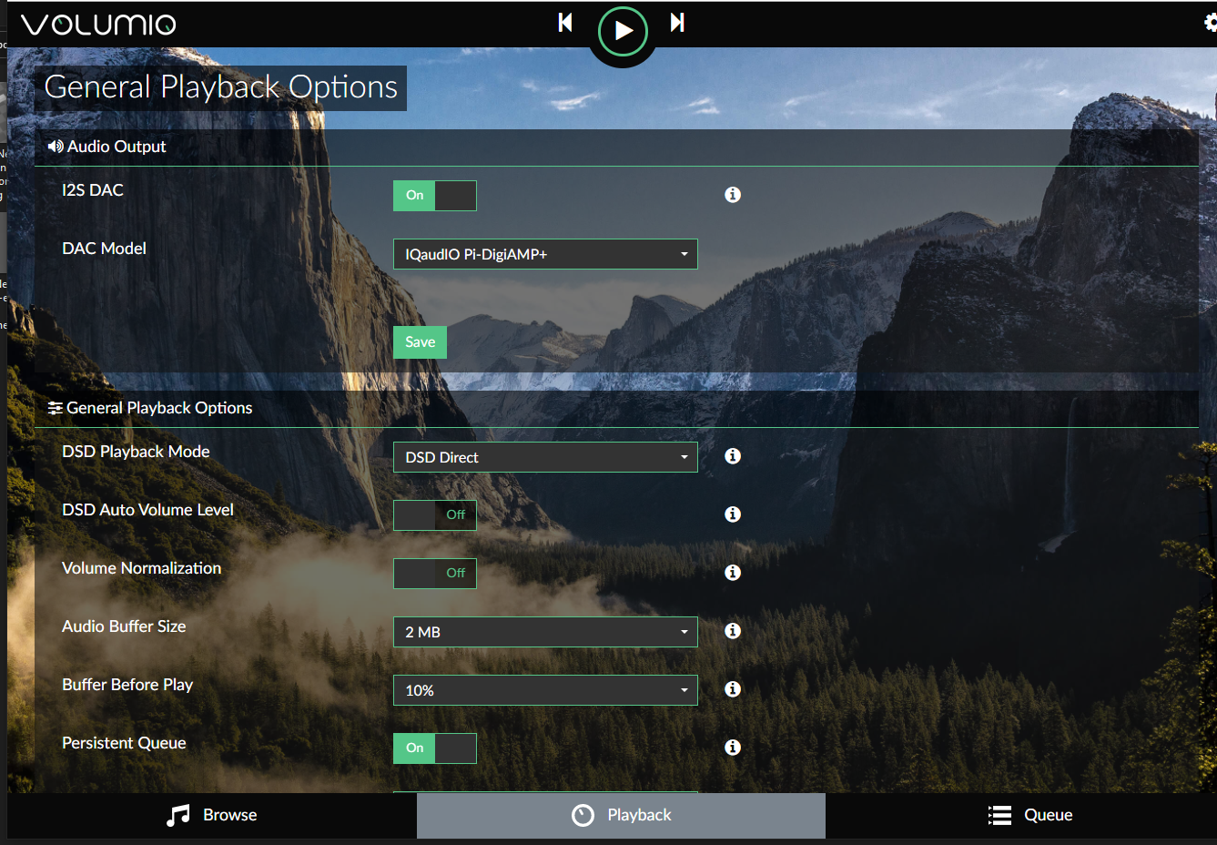
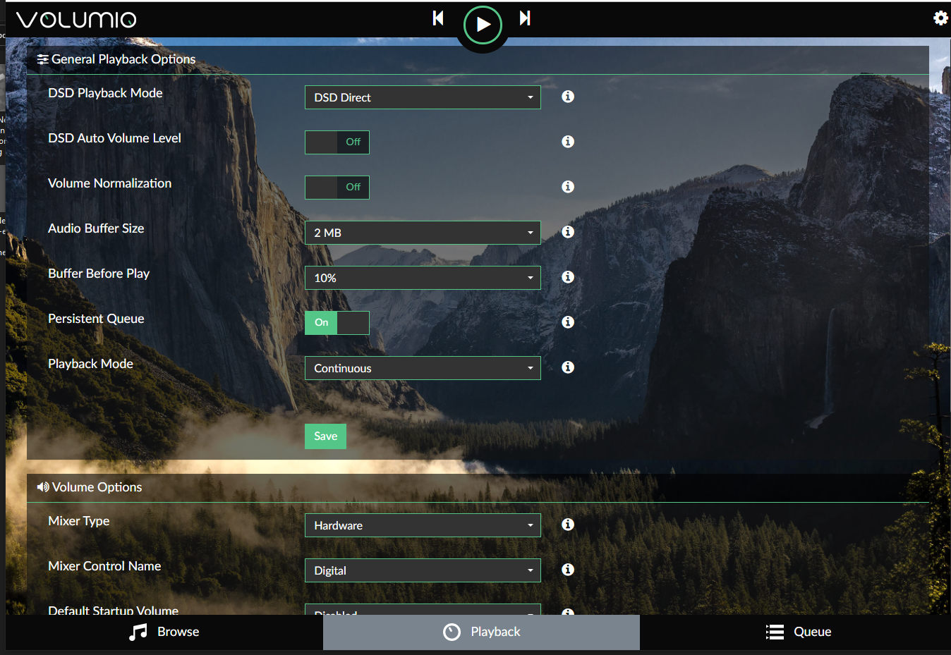
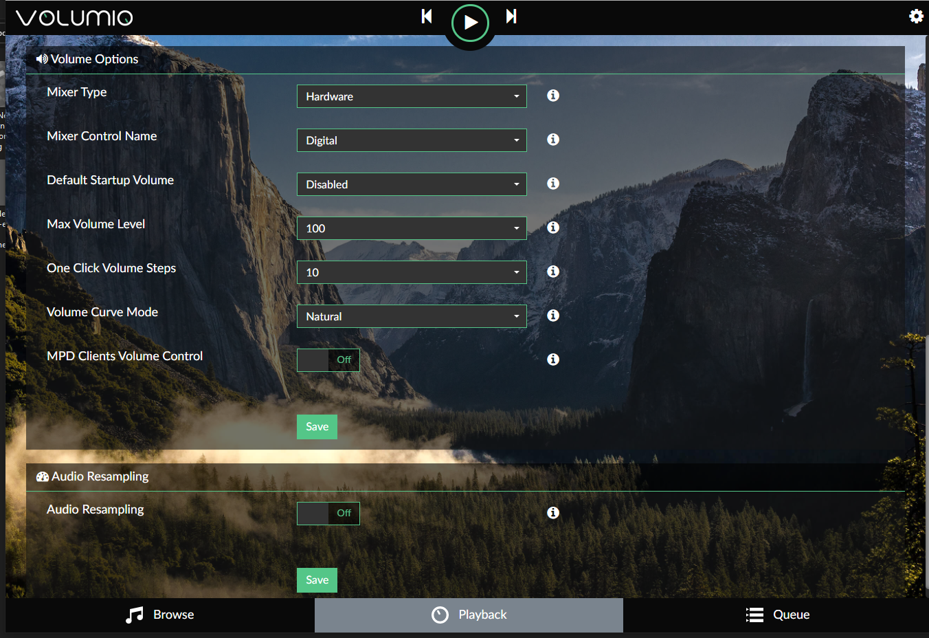
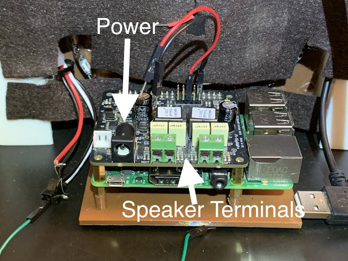
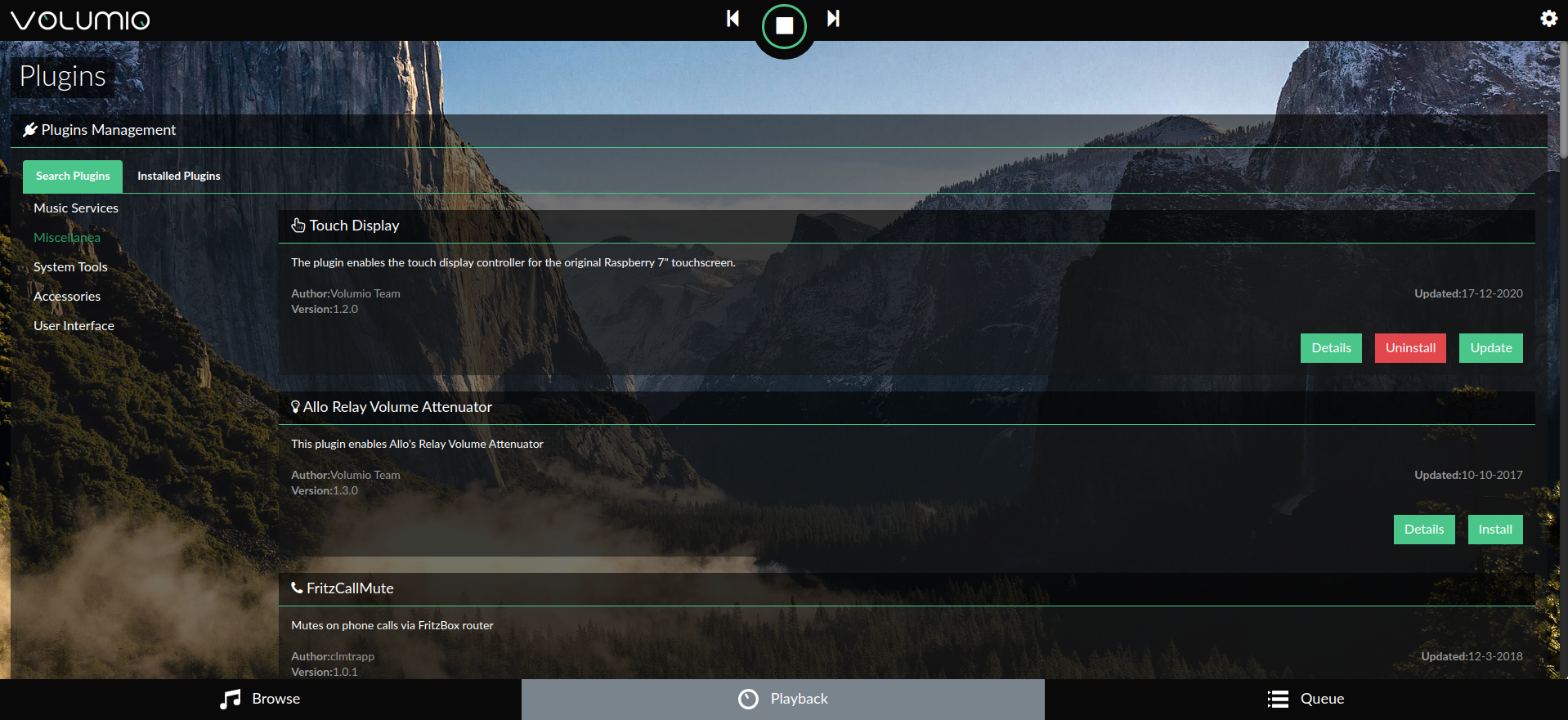
Pour commencer à utiliser Volumio, consultez le Guide de démarrage rapide et Premiers pas avec Volumio.
Préparer le circuit imprimé
Le facteur de forme de la carte Adafruit Perma-proto était un bon ajustement lorsqu'il était empilé sur le Pi et l'ampli IQAudio, et faisait une bonne carte porteuse/fille pour l'Arduino.
La carte n'est connectée qu'à l'IQAudio 5V et GND pour l'alimentation. Ainsi, l'en-tête femelle habituel pour se connecter à un Pi n'a pas été utilisé.
Pour une utilisation optimale de l'espace disponible sur la carte proto, orientez la carte de manière à ce que le rail marqué « 3.3V » soit en haut.
Je modifie la carte proto d'une manière un peu moins courante que le simple câblage point à point :
- Le rail 3,3 V sera en fait utilisé pour l'entrée 5 V .
- Traces de planche à découper pour placer plusieurs connexions à broches dans une colonne
- Découpage des traces de rail sur le rail 5V inférieur marqué par la carte, pour ajouter plusieurs broches dans une rangée
Ces éléments ont contribué à un tableau bien agencé, une fois rempli.
Consultez cette galerie de photos pour les connexions et modifications de câblage :
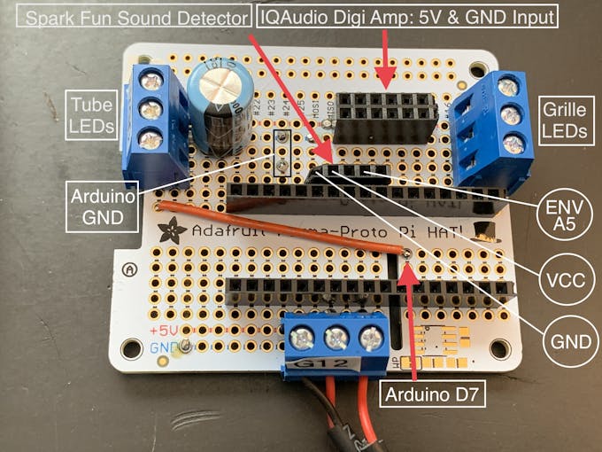
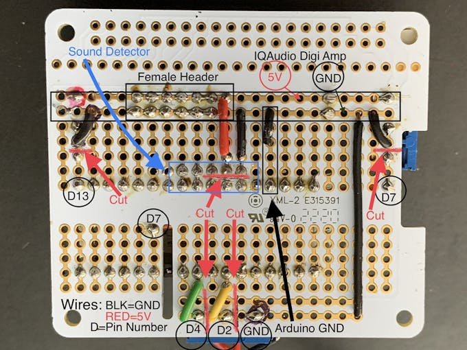
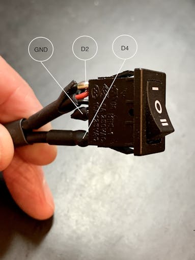
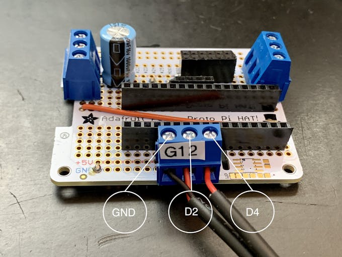
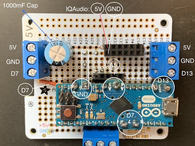
Remarque : Les bornes à 3 broches ont un pas de broche à broche de 5,08 mm. C'est exactement 2x le pas standard des vias de 2,54 mm sur la carte proto. Ainsi, les bornes à vis/broches sont séparées chacune de 2 vias de carte. La disposition de la planche et la découpe des traces dépendent de cet espacement. Vous ne pouvez pas remplacer une borne à 3 broches/2,54 mm sans changer la disposition de la carte.
Commutateur de sélection d'animation
Vous devez également câbler un interrupteur à bascule à trois positions, illustré sur les photos. Coupez 3 morceaux de fil de raccordement d'environ 7 pouces/18 cm pour cet interrupteur, de préférence deux noirs (GND) et un rouge (+V).
Plus d'informations sur ce commutateur ci-dessous.
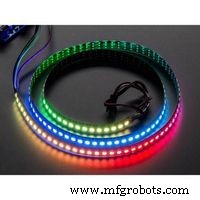
Néopixels
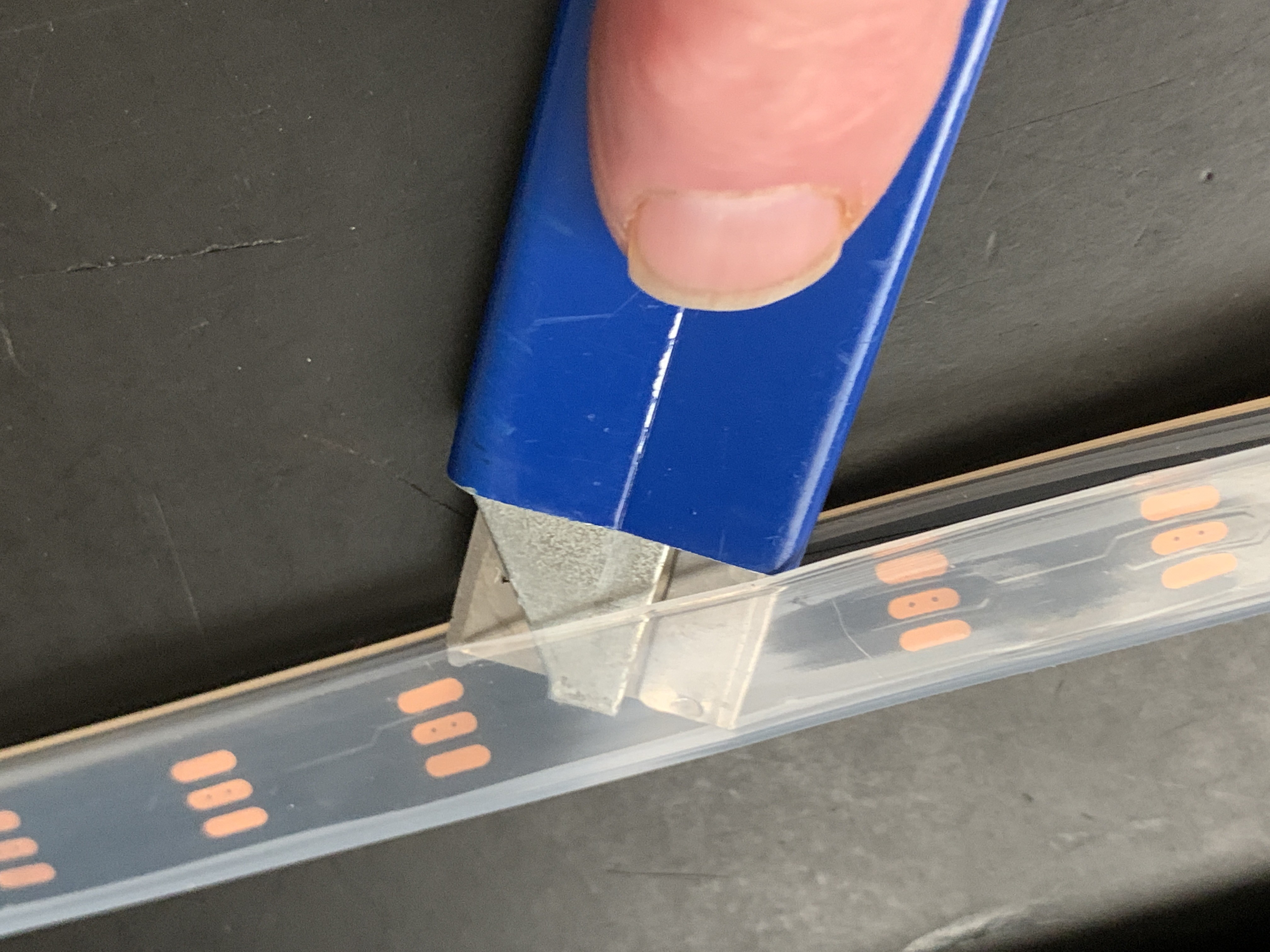
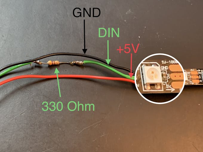
Retirez le revêtement en silicone d'une chaîne Neopixel d'un mètre. Coupez la bande Neopixel en deux sections, une de 36 LED et une de 22 LED. La bande courte entourera la calandre avant. La bande de longueur de 36 LED sera dans les tubes extérieurs (tubes néon). Coupez 3 morceaux de fil de connexion d'environ 7 pouces/18 cm pour chaque corde (vous pourrez les raccourcir plus tard). Câblez chaque section avec des fils pour GND, +V et DIN, en vous assurant de faire correspondre la direction DIN sur la chaîne. Ajoutez une résistance en ligne avec la connexion DIN (330 Ohm fonctionne).
Lumière des étoiles
Dans la calandre avant, il y a un insert imprimé en 3D en forme d'étoile à 6 branches (Star Light). Une LED RVB à fondu lent qui utilise +V et GND se monte derrière cette Star Light, insérée dans un déflecteur imprimé en 3D pour éviter les fuites de lumière. Branchez une résistance de 120 ohms en ligne sur le fil de liaison +V. Cela fera chuter le courant de 5V à environ 3,4V vers la LED. Ceci sera utilisé dans la section Assemblage/Tissu pour la grille, ci-dessous.
Arduino
Si vous n'avez pas encore installé l'IDE Arduino, téléchargez-le et installez-le en suivant ces instructions.
Vous aurez besoin de la bibliothèque Neopixel pour faire fonctionner les LED.
Les Neopixels réactifs au son sont basés sur l'esquisse Interactive LED Music Visualizer de Michael Bartlett sur Sparkfun. J'ai utilisé le "Full Visualizer" sans boutons, j'ai ajouté un interrupteur à bascule qui a trois fonctions :
- Les LED réagissent à la musique - position du commutateur 1
- DEL dans un motif "chaser" changeant de couleur, PAS de son réactif - position du commutateur 2
- Voyants éteints - position du commutateur au centre
Les LED ne fonctionneront que si l'interrupteur est connecté.
Téléchargez le sketch des LED du Jukebox depuis github.
Connexions
- Montez votre Arduino sur les en-têtes femelles de la carte proto
- Fixez la bande de 36 LED au terminal connecté à la broche numérique 7.
- Fixez la bande de 22 LED à la borne connectée à la broche numérique 13
- Insérez le détecteur de son Sparkfun.
- Fixez l'interrupteur à bascule :pôle central à GND, position 1 à la broche D2, position 2 à la broche D4
- Connectez l'IQAudio Digi Amp Plus +V et GND dans les embases femelles pour le rail 5V sur la carte Perma Proto (sur les photos ci-dessus)
- Connectez le RVB à fondu lent aux connecteurs femelles +V et GND
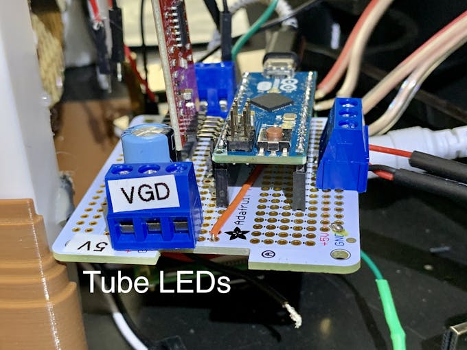
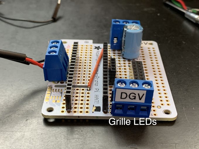
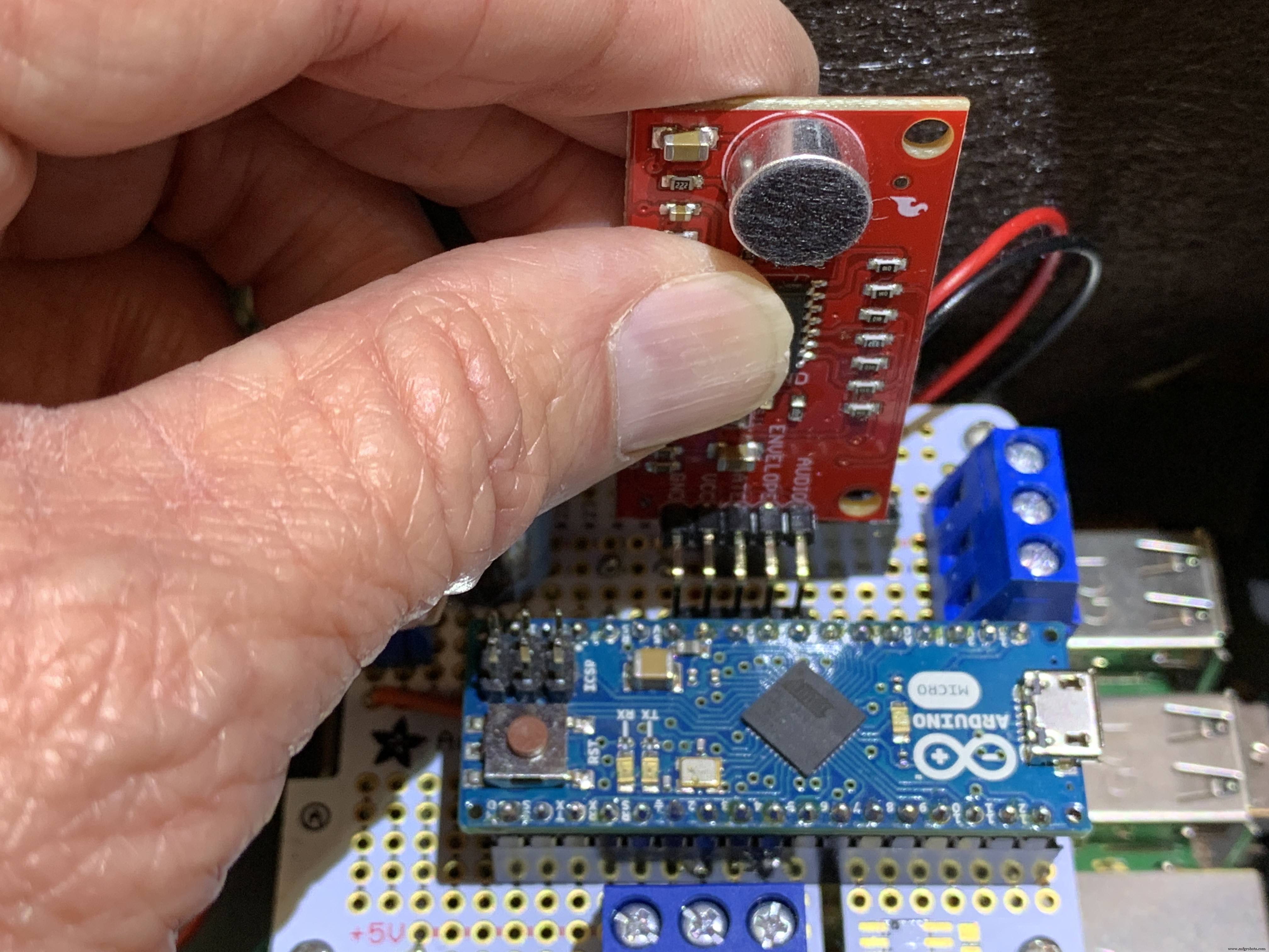
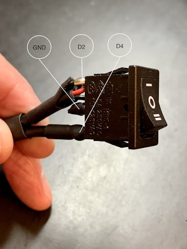
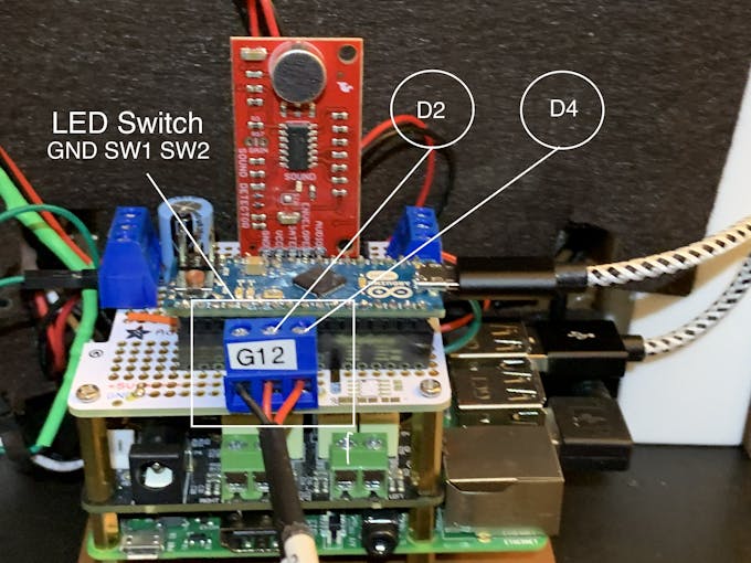
Téléchargez le croquis des LED Jukebox sur votre carte Arduino. The grille LEDs run through a RainbowCycle routine in the sketch setup function, which takes a little time. So the sound reactive LEDs won't work immediately. After the setup function runs, the grille LEDs will always remain on, unaffected by the position of the rocker switch. With music playing from Volumio, the Neon tubes should react to music with the 3-position rocker switch set to position one. Switch position two passes a color-wheel/chaser pattern through the Neon tubes. Center position on this switch turns the Neon LEDs off.
3D Printing
Check the docs folder of the github download for part identification (Parts List) and Print Times for each part. There are also screenshots of the Prusa Slicer parameters and orientation to guide how to print each part. Find those in the 3D-Prints folder.
REMARQUE : All images are of the prototype jukebox I built. These will look different from the published Fusion 360 design archive and STL files. The final release STL files include improvements for the following:
- Increase the size of the bezel on the LCD touch screen
- Increase the size of the mounting plate to allow more clearance
- Remove the 3D printed standoffs on the mounting plate and just use holes with screws inserted from the bottom of the mounting plate
- Simplified the back cover
Assembly
Tools
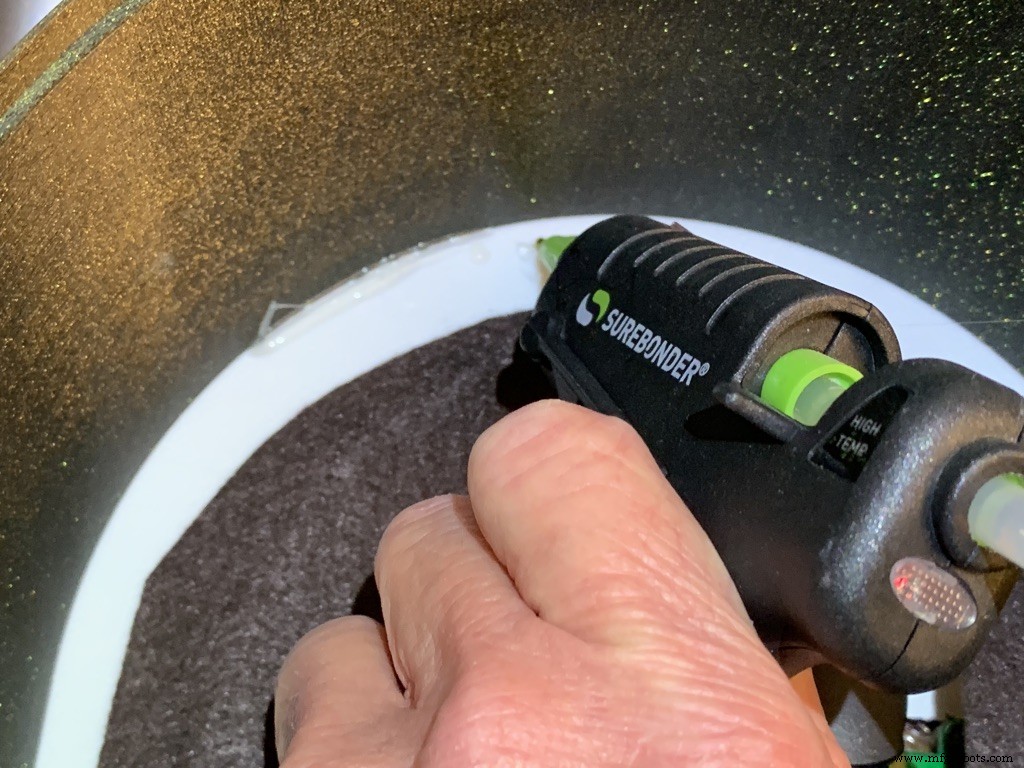
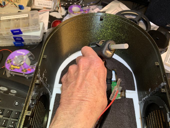
I used a fine-tipped hot glue gun so I could get into smaller spaces. These use smaller diameter glue sticks, and lots of them.
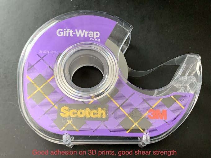
I used some tape I had on hand to temporarily hold the parts together for gluing. I found Scotch Gift-Wrap tape was actually pretty good for this. It has good adhesion and strong shear strength.
Enclosure
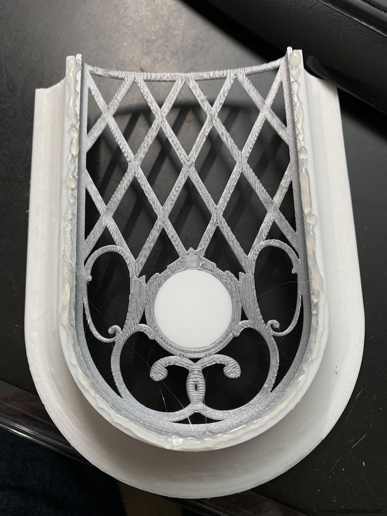
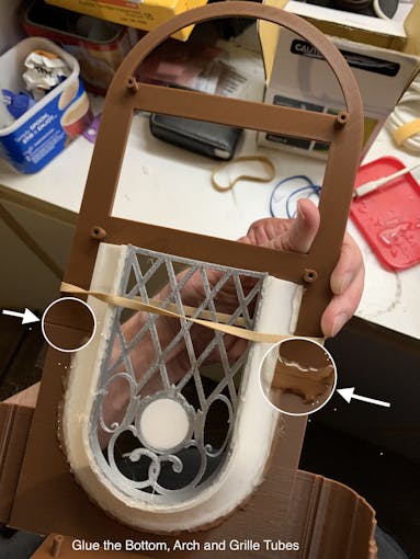
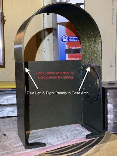
The parts are glued in starting from the inside, the Grille, and moving to the outside, the Neon Tubes, as shown in the video below.
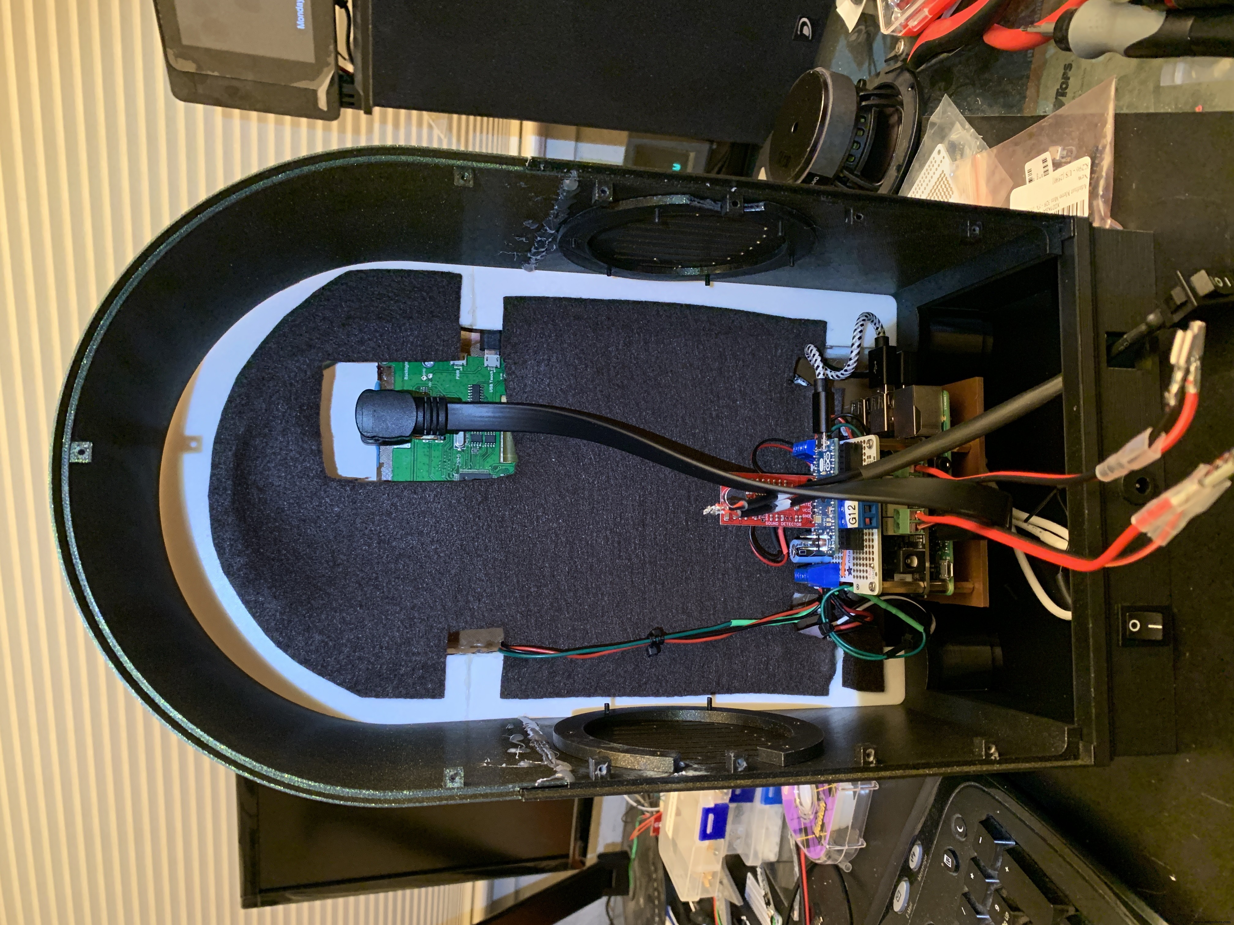
Pause after gluing the Neon Tubes and mount the following hardware. This will give you more space to work in, before you glue in the back case. Refer to the Assembly Gallery photos below for details.
- Acrylic Window with photo
- NeoPixels
- LCD Touch Screen
- Grille Cloth and Star Light Holder
- Raspberry Pi/IQAudio Pi Digi Amp/Arduino
- Adhesive Felt (or paper) backing
- Base with switches
Then continue gluing the Case and Base to the other assembled parts.
After the case is fully assembled and glued together, mount the Speakers and add Decorations.
There is an optional two-piece 3D printed case cover that screws into the back of the case.
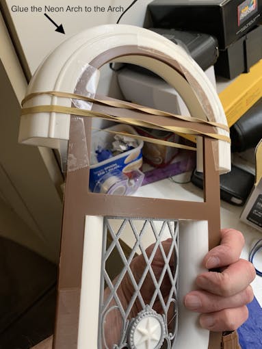
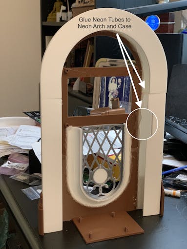
_k2oC39lKQk.jpeg?auto=compress%2Cformat&w=680&h=510&fit=max)
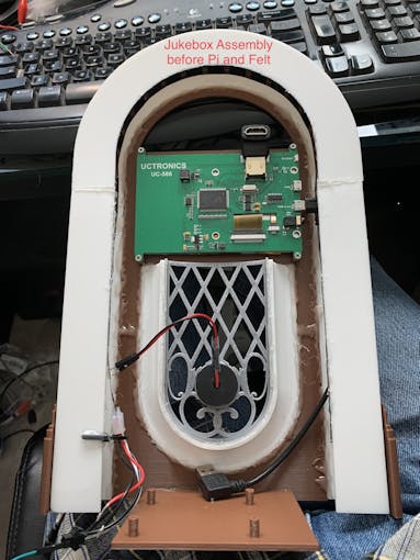
Mounting the Hardware
In the following, all the hardware mentioned is found in the "Things" section.
“Right” and “Left“ are your right and left as you face the front of the jukebox.
Acrylic Window and Photo
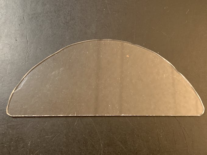
Use a rotary tool (eg., Dremel) at slow speed to cut a piece of clear acrylic. There is a template for this in the github download. Tape the template down on the acrylic and cut around the outside. Sand the edges and use CA to glue into the top of the Arch. Print a photo of your choice that will fill up the visible area and glue that in back of the acrylic.
NeoPixels
Glue the long LED strip edge-on to the Neon Tubes, so that the LEDs are facing inward to the Tubes. There is a small space between the LED and the edge of the strip that can help fit the string against the Neon Tubes. Align that to glue down.
The Grille Tube NeoPixels will be glued onto the Left and Right Bottom, with a "U" shape near the board mounting plate. Hold the strip down with pieces of tape and tack spots with hot glue. When those are solid, remove the tape and fill in the spots where the tape was with more glue.
LCD Touch Screen
Screw the Touch Screen into the mounting posts at the top of the Arch, below the Acrylic window. The HDMI Touch Screen input is on the top of the screen. You need to insert a 90 degree to 270 degree HDMI adapter there, Plug the HDMI 1 ft. Male-to-Male flat cable into the adapter. The other end plugs into a Raspberry Pi 3. (If you're using a Raspberry Pi 4, you need a different cable that has a Micro HDMI in one end). Insert the Left-angle Micro USB to the Touch port on the LCD, and the USB-A end to a Raspberry Pi port. Thread this cable through the left Neon Tube.
Grille Cloth and Star Light Holder
The Grille will be backed with "speaker cloth" to hide the inside of the jukebox. There will be an LED holder behind the Star Light to prevent light bleed, and a hole needs to be cut into the cloth for that.
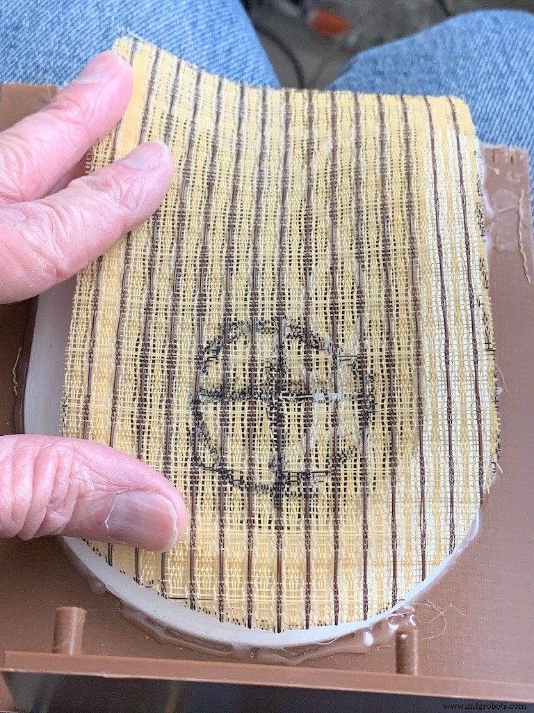
Cut a piece of speaker cloth large enough to cover the Grille and the edges of the Grille tubes. Use the Star Light LED 3D printed holder as a guide and mark the speaker cloth in a circle for the outside of the holder. Mark a cross in the center of the circle Cut the two lines of the cross to make 4 sections. Cut the rounded part of each section to make a hole for the LED holder.
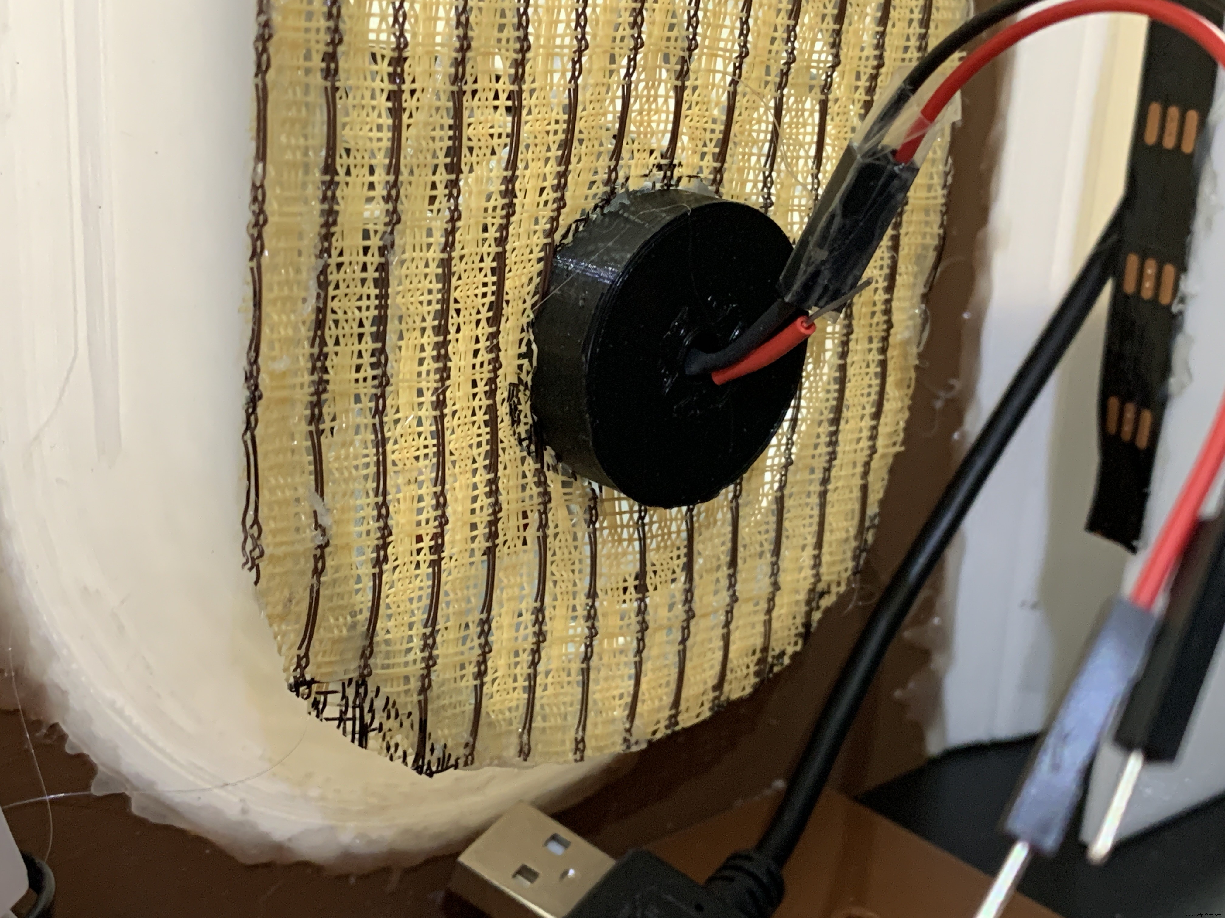
Mount the color-changing LED mentioned in the section Prepare the Circuit Board/Star Light, above. Insert the LED into the holder and glue it to the Star Light. CA will work well here.
With the LED holder glued in place, fit the speaker cloth over the holder and the Grille. Stretch and glue the edges of the cloth to the Grille Tubes.
Raspberry Pi/IQAudio Pi Digi Amp/Arduino
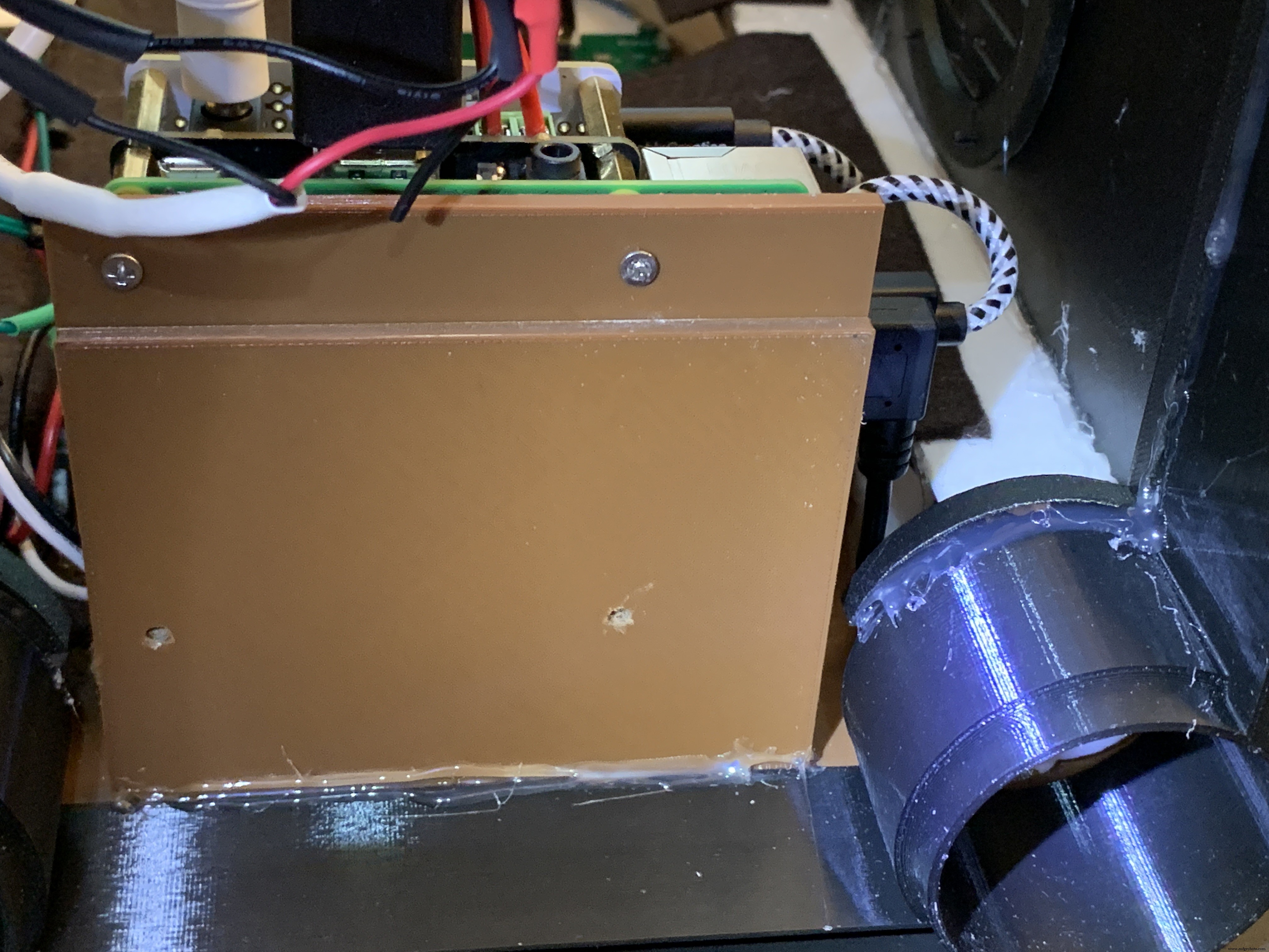
Mount the Pi and other boards (you assembled and tested it in Getting Started, Right ?) onto the mounting plate with screws into the Pi's 5mm bottom standoffs. Plug the LCD HDMI and USB cables into the mounted Pi. There's an additional 6 inch Micro USB to Micro A cable. Plug the Micro end into the Arduino and the other end into the Pi to power the Arduino.
The Star Light +5V and GND plug into the power from the Digi Amp Plus +5V/GND rails.
Adhesive Felt
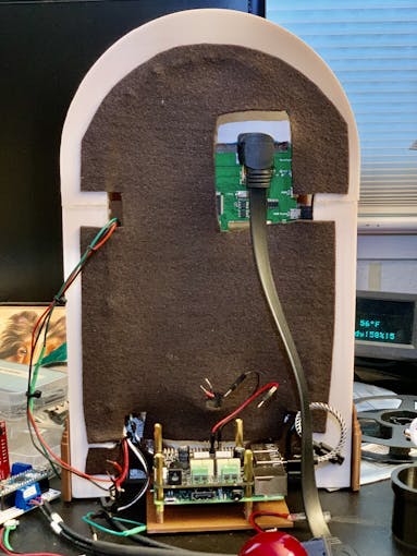
To prevent light bleed, cover the inside with craft felt, which has its own adhesive backing Test fit the felt and cut holes to allow for cables and wires to pass through.
Base with Switches
In addition to the Animation Selector Switch, there is an on-off rocker switch that is connected to a panel-mount jack.
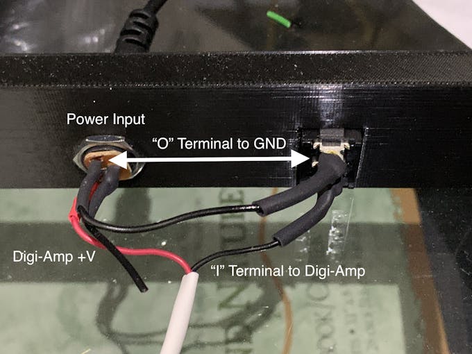
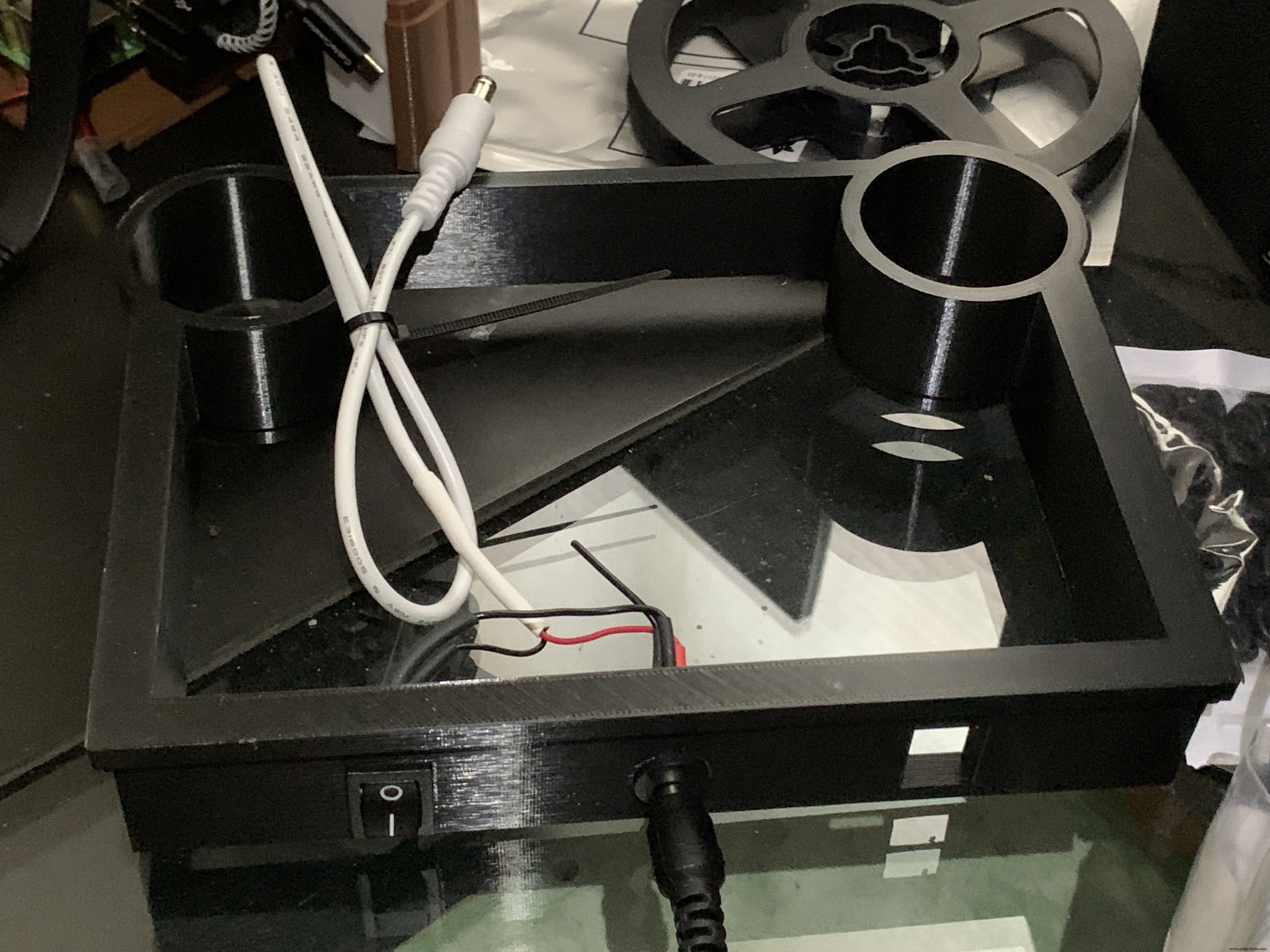
Cut one GND (black) wire at least 80 mm long for this switch. Strip the insulating jacket off the power extension cable (white) in pictures about 80 mm long to expose a red and a black wire. Insert the barrel power connector and the on-off rocker switch into the base.
Solder the cut black wire to the terminal marked "O" on one end, the other end to the active GND pin on the barrel power connector. The other terminal "I" is soldered to the GND (black) of the power extension cable for the Digi Amp Plus Finally, the +V (red) of the power extension cable is soldered to the +V terminal of the barrel connector.
Plug the extension connector into the Pi Digi Amp Plus. Glue the Base onto the Bottom and Case.
Speakers
The Dayton Audio RS100-8 speakers have a cone in the middle that prevents them from being mounted flush to a solid grille, as on this jukebox. If you're using these speakers (or some where the center protrudes), you'll have to use a mounting ring (3D file supplied) so the speakers can mount properly.
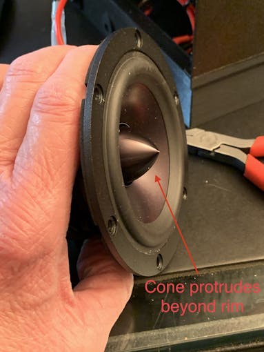
For the last step of assembly, screw the speakers in with 15 mm M2.5 metal screws and nuts.
Tip: To make assembly easier, mount the speaker rings to the case with the screws pushed in for alignment in the holes. Tack down with hot glue or CA glue. When solid, mount the speakers to the rings.
I had pretty good luck holding the tiny nuts down with my index finger and turning the screw to get the nuts started.
However, there is one screw hole straight back on each side that has very little clearance. It is hard to get the nut started on that screw. Putting blu-tack or tape on the nut may help position it to get it started.
Eventually, I did get all the nuts fastened.
Decorations
There are decorations on top and the two sides of the jukebox, with details in the github 3D Parts List document:
- Neon Tube Red Cover
- Neon Tube Fan Decoration
- Neon Tube Ornament
- Case Joint Cover
- Top Red Ornament
- Top Ornament
Repeat for Left &Right:
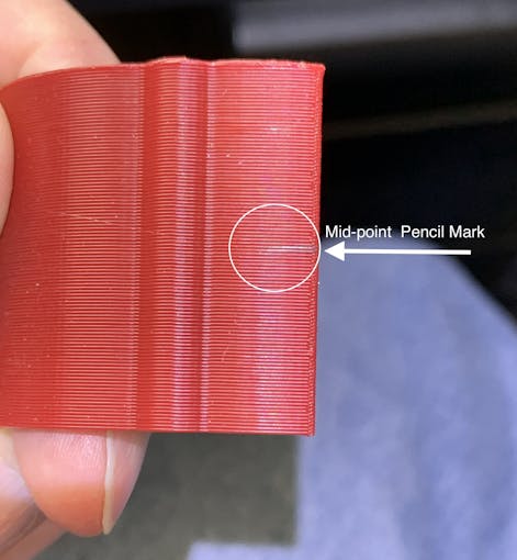
For the Neon Tubes, use a small ruler to mark the halfway point on the side of the Red Cover with a pencil. Then, match that to the Neon Tube joints and glue with CA.
The long Case Joint Cover aligns to the Neon Tube Red Cover and glues down to the case.
Gllue the Fan Decoration and Ornament at the top and bottom of the Red Cover
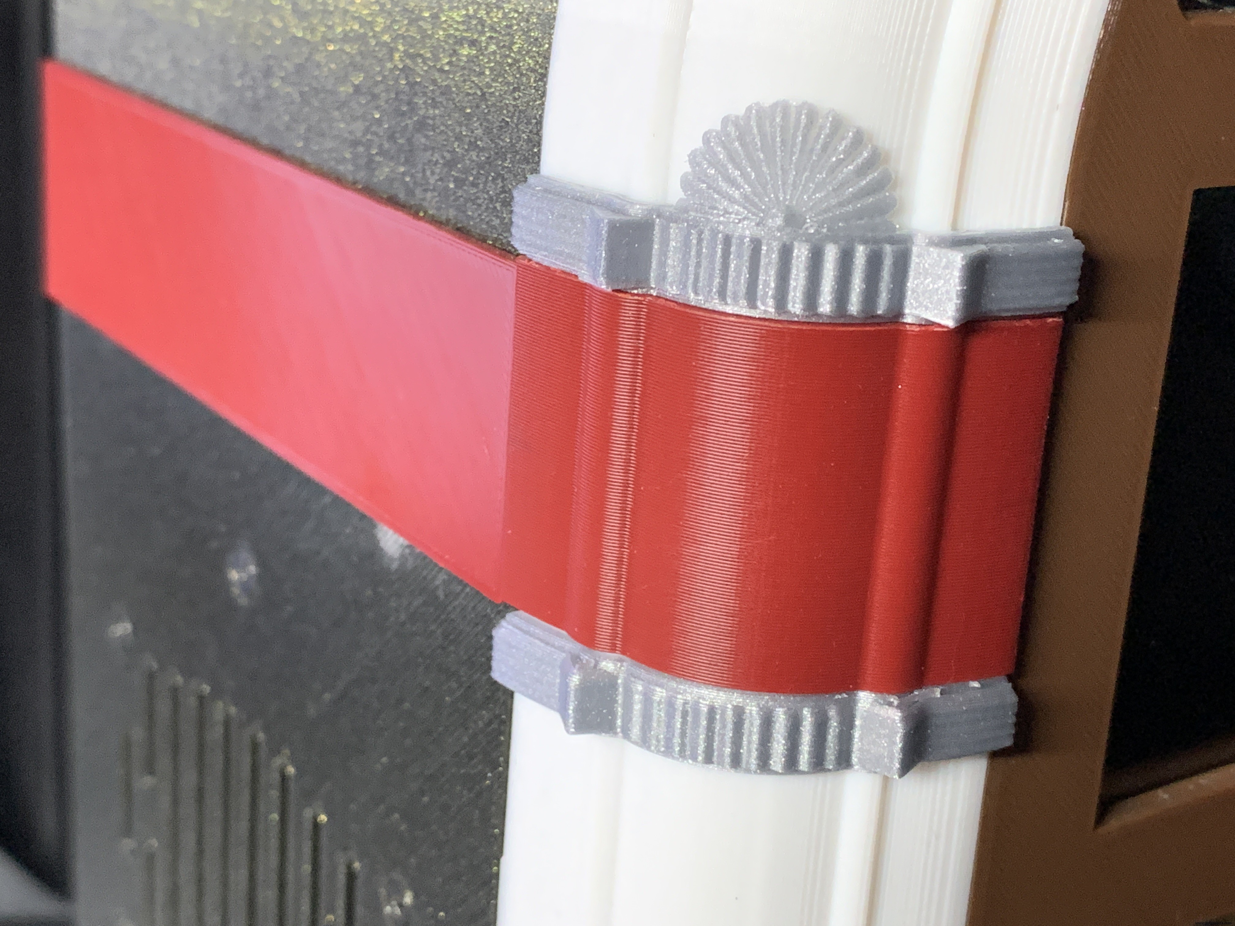
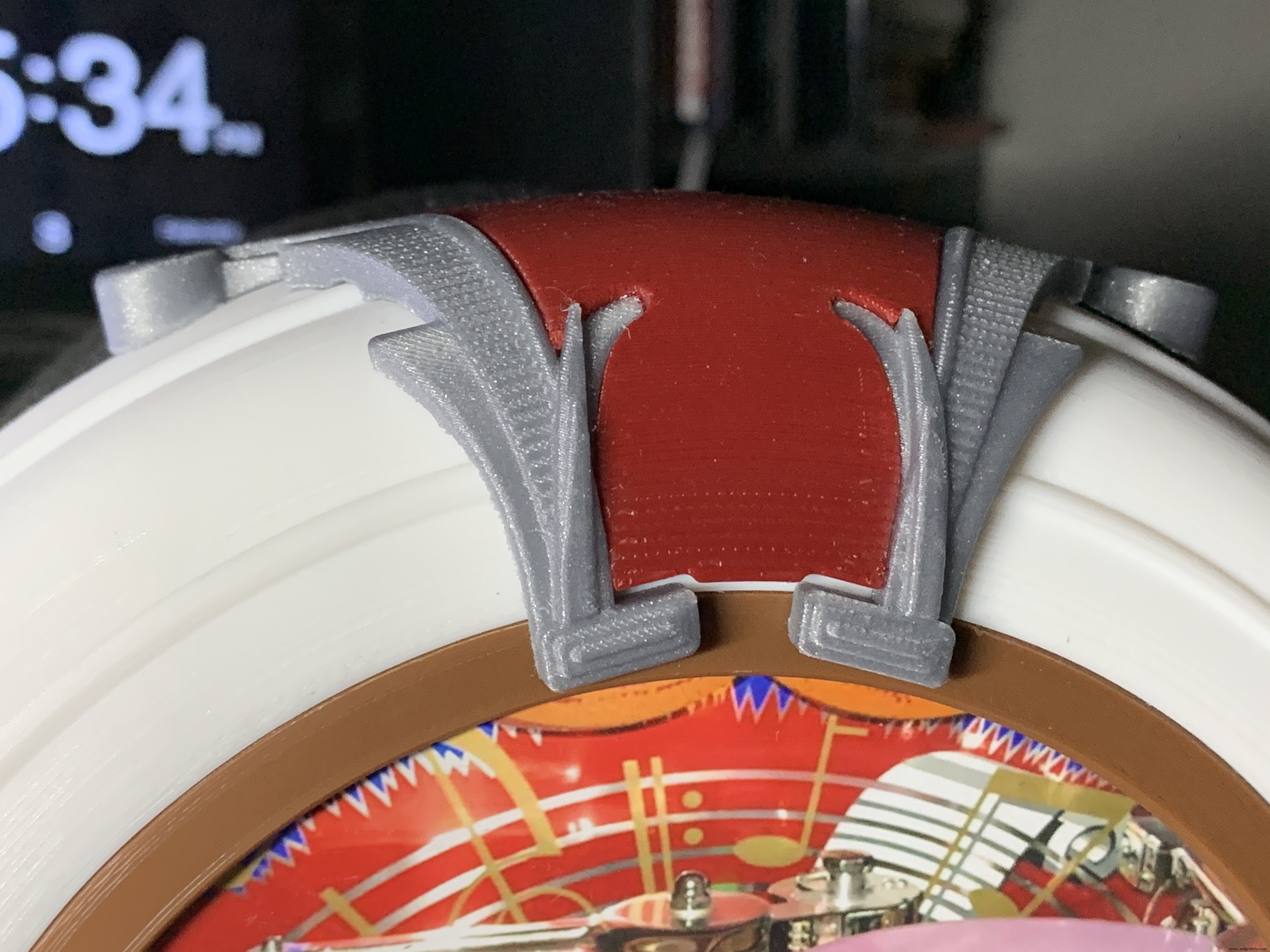
The Top Ornament (2 separate pieces) fits into the Top Red Ornament and is glued together as an assembly.
For alignment, make a pencil mark midway at the top of the Arch and another mark midway on the Top Red Cover. Align these two marks and glue.
Operation
Volumio has a fairly intuitive user interface that's easy to use.
To get started, press/select the 'Home' icon or the 'Browse' button from the 'Playback' window..You'll see something like the image below, depending on what options you have installed.
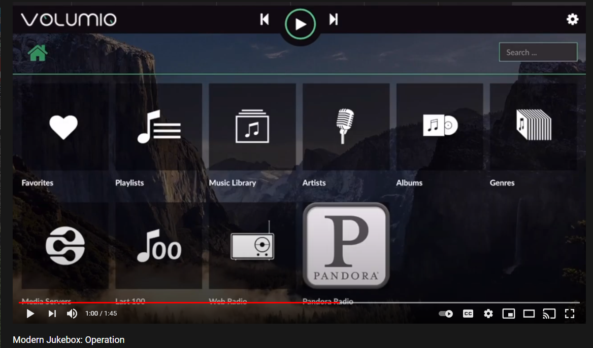
For Pandora and Spotify (paid subscription required), go to Settings/Plugins/Music Services. You can connect to Volumio from AirPlay with the Apple Music player.
Update September 20, 2021:
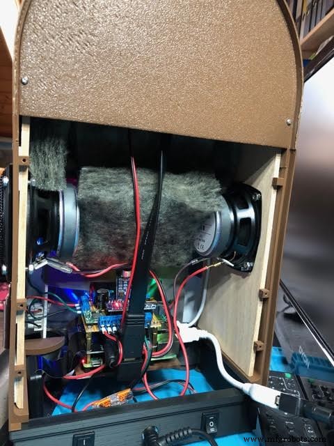
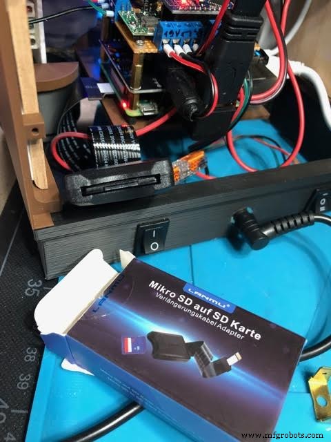
Raimund Trierscheid made a version of the Modern Jukebox, with improvements! Raimund added 5mm wood panels to the sides of the case to hold the heavy speakers and improve the sound.
Here are some photos:
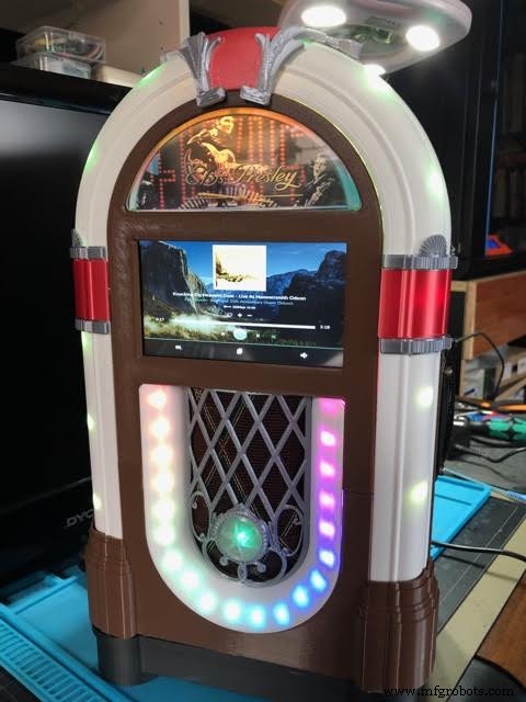
Code
Modern-Jukebox on github
https://github.com/thisoldgeek/Modern-JukeboxPièces et boîtiers personnalisés
Fusion 360 design modern_jukebox_r1_v2_dccOE3MSIQ.f3dProcessus de fabrication


