


Développez-le vous-même | GIY
Composants et fournitures
 |
| × | 1 | |||
 |
| × | 1 | |||
 |
| × | 1 | |||
 |
| × | 4 | |||
 |
| × | 1 | |||
 |
| × | 1 | |||
 |
| × | 1 | |||
 |
| × | 1 | |||
 |
| × | 1 | |||
 |
| × | 1 |
Outils et machines nécessaires
| |
| |||
| |
|
Applications et services en ligne
 |
| |||
 |
|
À propos de ce projet
Présentation
J'ai été grandement inspiré après avoir regardé le TED Talk sur l'agriculture numérique, prononcé par le directeur de l'Open Agriculture Initiative du MIT, Caleb Harper, qui a abordé le sujet :Cet ordinateur fera pousser votre nourriture dans le futur . La question la plus importante abordée dans son discours qui m'a vraiment inspiré était Et si nous pouvions cultiver de délicieux aliments riches en nutriments, à l'intérieur n'importe où dans le monde ? Et voilà l'idée est née !
Donc, ce que j'essaie de faire, c'est quelque chose comme une boîte ou un incubateur, qui est capable de créer les conditions climatiques idéales nécessaires à la croissance, fournissant exactement la quantité de lumière et de nutriments dont une plante a besoin. Je souhaite créer un émulateur de lumière solaire, un système d'irrigation et un contrôleur de climat intégrés dans un design élégant et moderne.

Je prévois d'atteindre les résultats souhaités en mettant en œuvre la technologie suivante :
Faire pousser la lumière LED - la chlorophylle des plantes ne répond principalement qu'à deux longueurs d'onde, représentées par 450 nm et 650 nm. Le système LED que je prévois d'utiliser aura une combinaison de lumières LED rouges et bleues pour fournir le mélange parfait pour aider à la fois à la croissance végétative et à la floraison.
Atomiseur à ultrasons (fabriquant de brouillard) - Je souhaite utiliser une nouvelle méthode d'irrigation, que j'ai découverte par moi-même récemment, appelée aéroponie (FogPonics) qui arrose les plantes à l'aide d'un brouillard infusé d'engrais.
Dosage automatique des nutriments - Ce système dosera automatiquement les nutriments pour les plantes exactement quand elles en ont besoin.
Système de détection d'eau - Je souhaite équiper mon système de capteurs de pH et de TDS (Total Dissolved Solids) pour aider à maintenir une valeur de pH équilibrée dans le réservoir d'eau qui conviendra le mieux aux plantes ainsi que de savoir et d'alerter quand doser les nutriments.
Système d'échange d'eau - le système doit être équipé d'un branchement pour les changements d'eau automatiques. Je veux rendre ce processus facile et contrôlé par un simple clic.
Système de contrôle d'air - Il permet d'avoir un contrôle précis de la température et de l'humidité à l'intérieur du système, jusqu'au degré près. La technologie derrière implique l'utilisation d'un capteur de température/humidité comme le DHT22 ou le DHT11 pour recevoir les données, et un ventilateur avec un serpentin pour le réguler en conséquence.
Application mobile - Je veux vraiment créer une application pour la première fois de ma vie ! Cette application doit inclure des informations en temps réel sur le niveau de pH, la température, l'humidité, les nutriments, les ppm, etc. et une représentation graphique dans le temps afin de suivre les statistiques et de partager les progrès de la croissance sur les réseaux sociaux. Je souhaite également mettre en place des alertes intelligentes qui me permettront de savoir quand le système aura besoin de mon implication. Je veux aussi non seulement recevoir la représentation des données sur mon téléphone, mais aussi pouvoir configurer les conditions climatiques à l'intérieur du système !
Malheureusement, je ne suis pas le premier à avoir eu ce genre d'idée, mais la meilleure façon de trouver une idée créative est d'améliorer celles qui existent !
Il existe plusieurs projets similaires sur le marché, cependant, malgré tous les avantages individuels, ils présentent également des inconvénients tels que prendre trop de place ou être trop petits, trop chers, ne cultiver qu'une seule culture à la fois, etc. rechercher et analyser soigneusement les forces et les faiblesses des projets disponibles, et compte tenu de la réponse du marché, je souhaite proposer un nouveau système open source avancé, qui réduira les inconvénients et n'implémentera que les meilleures fonctionnalités.
Très ambitieux, n'est-ce pas ? Mais essayez-le
Expériences
Traiter avec les plantes prend beaucoup de temps ! Ils ont généralement besoin de plusieurs semaines à plusieurs mois pour pousser, et je dois être prêt pour cela !
Parce que je sais déjà ce que je veux construire pour mon projet final, je dois m'en occuper en amont et ne pas tout laisser au dernier moment. C'est pourquoi, je vais commencer à tester et à expérimenter dès que possible !
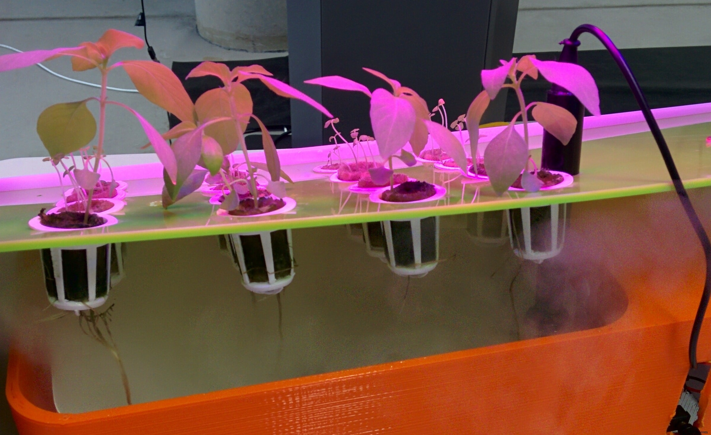
La première chose que je veux découvrir, c'est le fait que faire pousser des plantes en utilisant une brume riche en nutriments et faire pousser des lumières LED c'est mieux qu'un système conventionnel dans le sol et la lumière naturelle du soleil ! En théorie, cela devrait être exactement le cas, mais je ne crois rien tant que je ne l'ai pas essayé !
J'ai donc décidé de lancer ma propre expérience, qui va me demander du temps, et elle consiste à diviser les plantes en plusieurs groupes :
- (Sol + Soleil) - ce groupe poussera dans des conditions absolument naturelles, planté dans le sol et placé sur le rebord de la fenêtre.
- (Brouillard + Soleil) - ce groupe sera placé dans un récipient, qui contiendra une brume riche en nutriments, et également placé sur le même rebord de fenêtre
- (Lumière LED Sol + Culture) - ce groupe sera dans le sol, mais utilisera la lumière artificielle Grow LED au lieu de la lumière du soleil
- (Fog + Grow LED light) - c'est censé être le HÉROS groupe) Parce que mon futur système mettra en œuvre ces deux fonctionnalités, la lumière LED de croissance et le nuage de brouillard riche en nutriments, j'espère découvrir que cette combinaison donnera les meilleurs résultats !
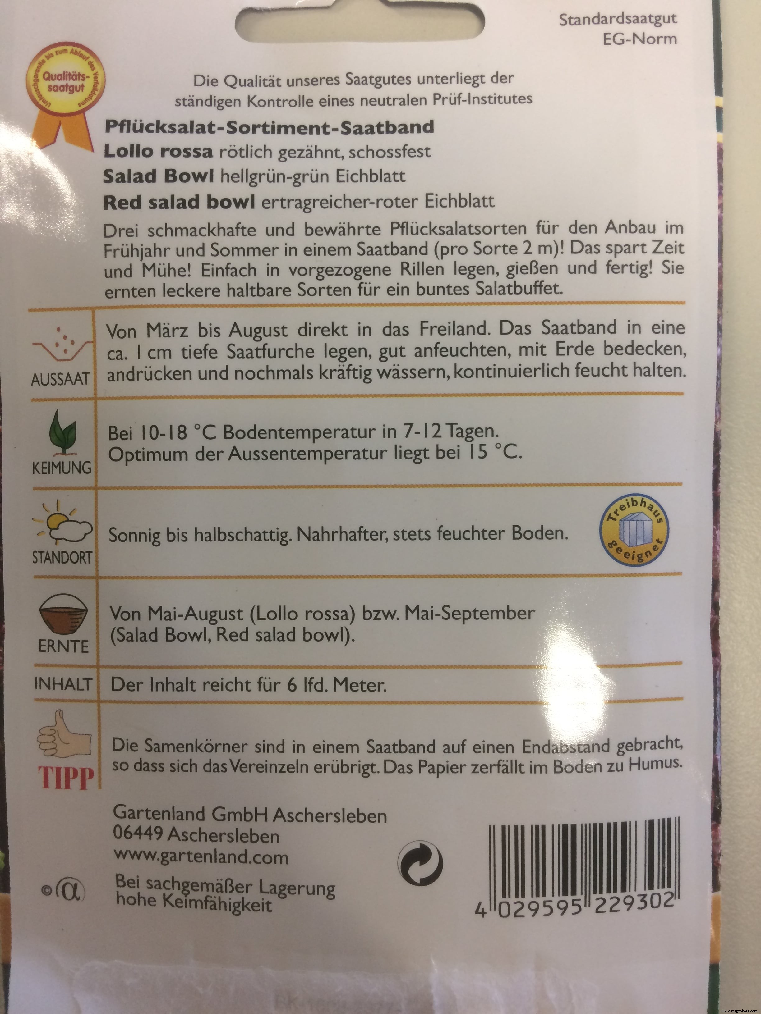
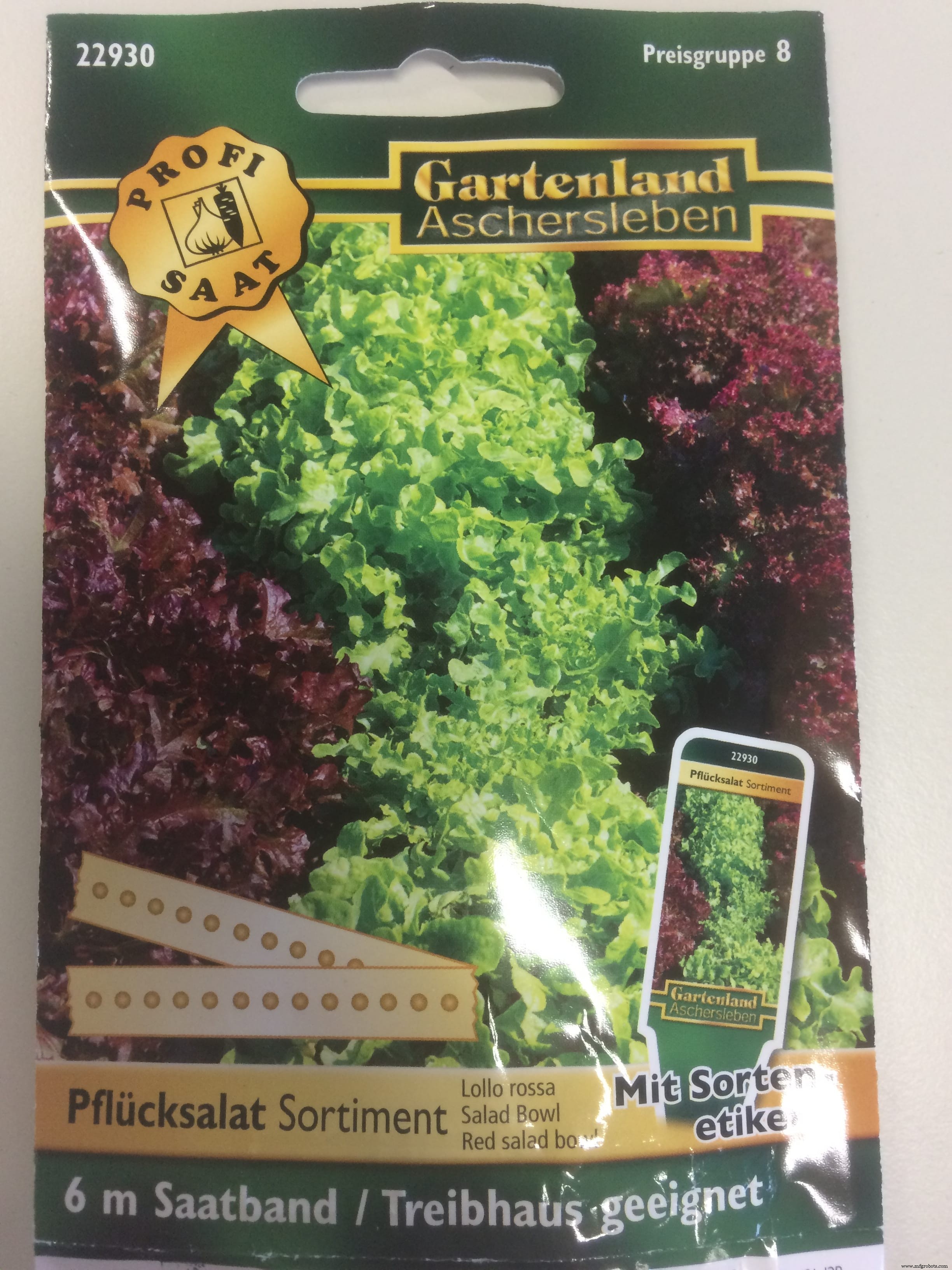
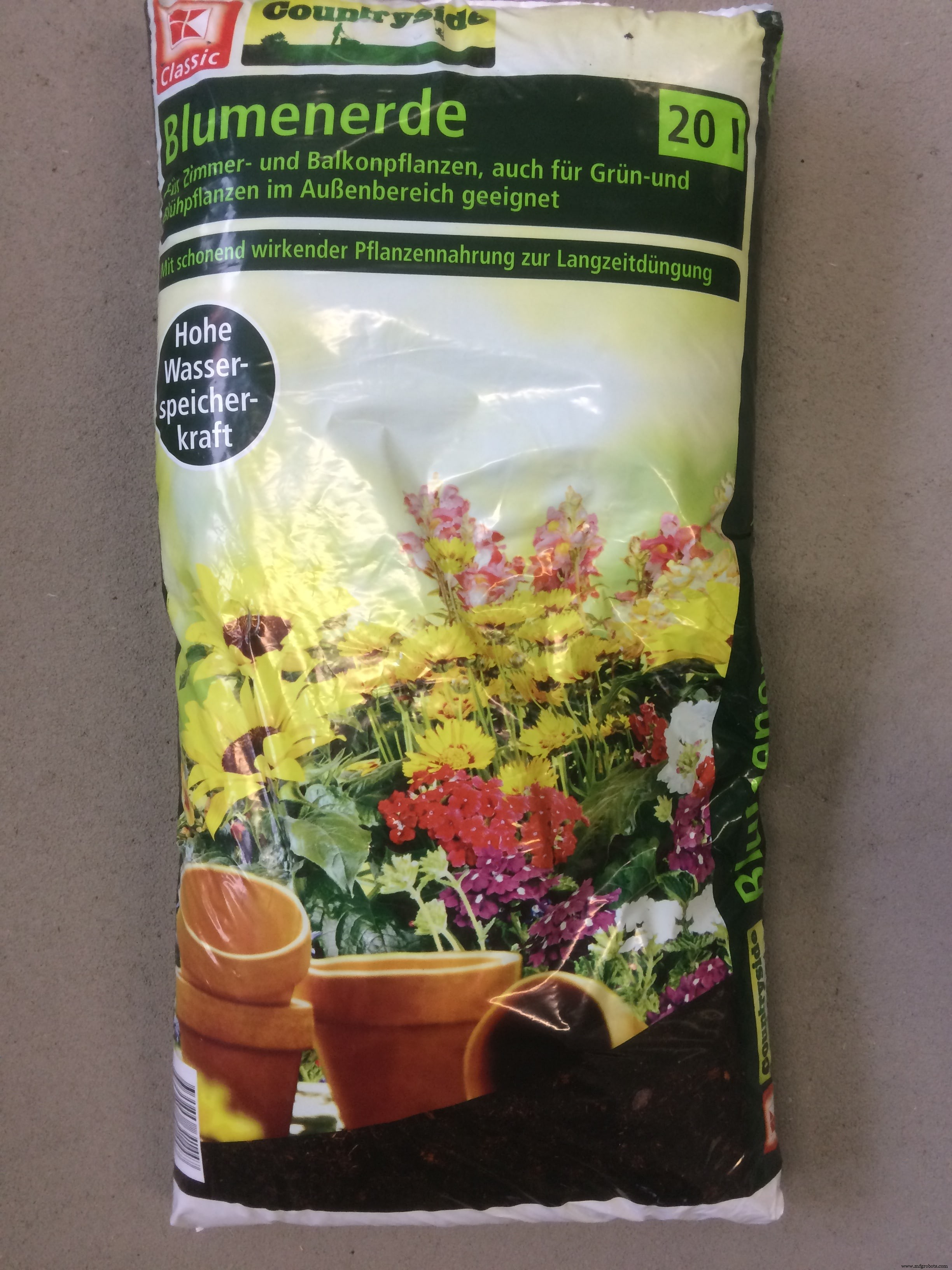
Dans le magasin allemand local Kaufland, au rayon des plantes, j'ai acheté les graines d'herbes mélangées. Ce seront mes bébés de test :p
C'était la première fois de ma vie que je plantais quelque chose :D ne me juge pas si j'ai fait quelque chose de mal !)
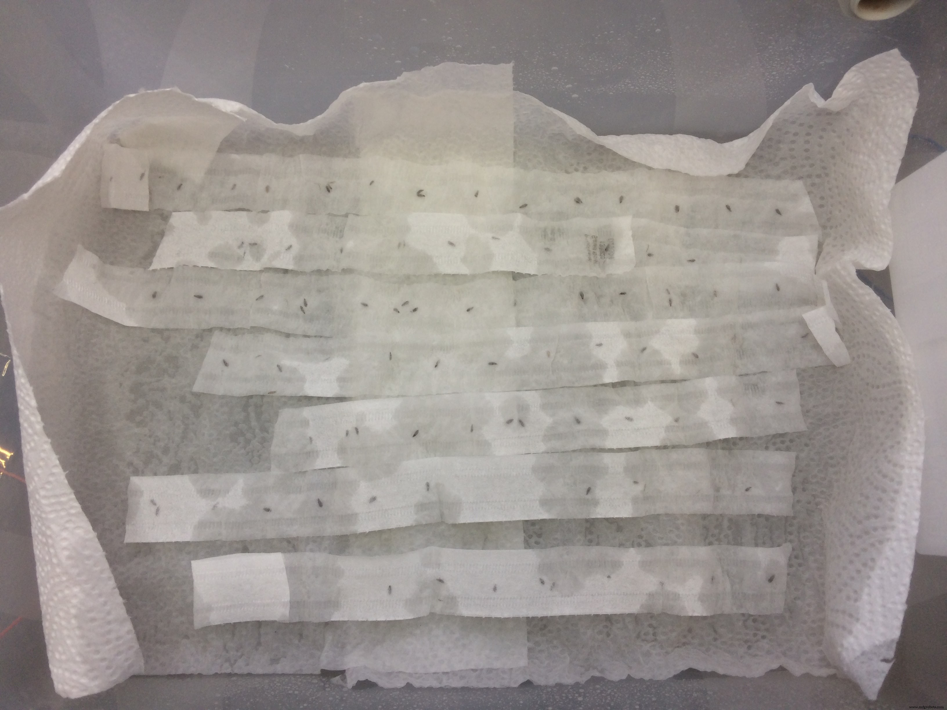
J'ai consulté plusieurs tutoriels auparavant et j'ai appris que je devais d'abord faire germer les graines. J'ai eu un récipient en plastique, où j'ai placé les graines, et les ai recouvertes d'une serviette en papier. A ce stade, ils ont besoin de presque 100% d'humidité, c'est pourquoi j'ai utilisé un spray pour arroser les serviettes en papier, et j'ai recouvert le récipient avec le sac en plastique, afin que l'eau ne s'évapore pas.
J'ai laissé les graines pendant 1,5 semaine, et quand j'ai ouvert le récipient, j'ai été vraiment surpris !
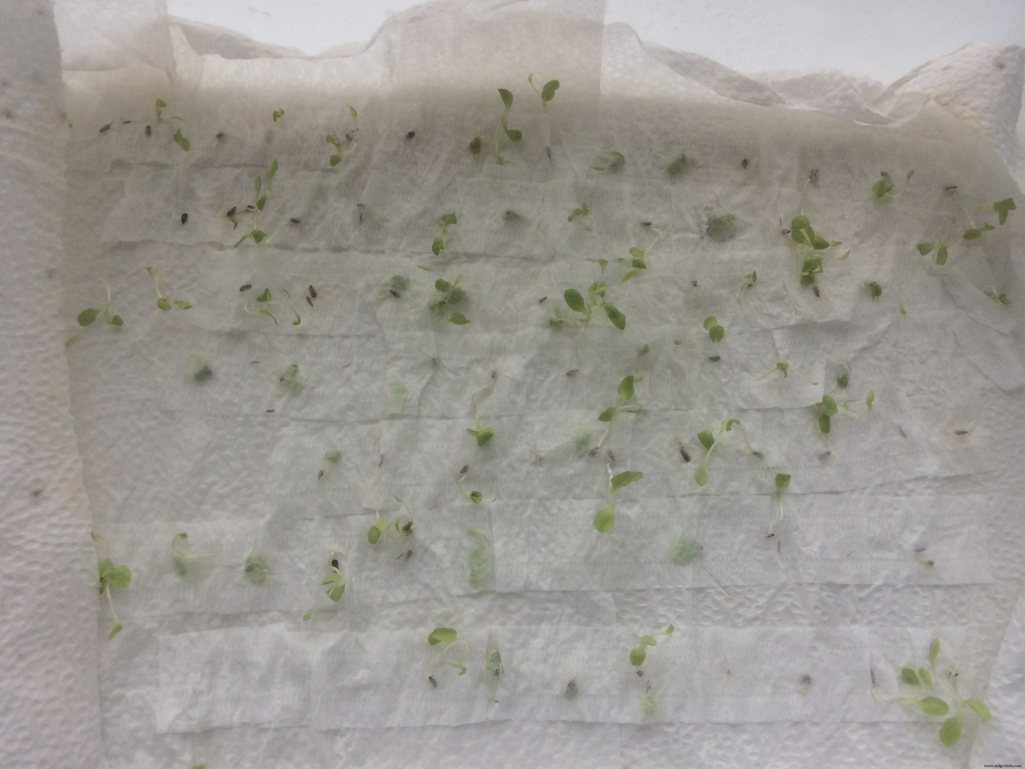
Presque toutes les graines ont germé ! J'étais heureux comme un enfant)
Ensuite, je devais sélectionner les meilleures petites plantes, celles qui avaient la tige la plus épaisse et qui avaient l'air plus grosses et meilleures dans l'ensemble.
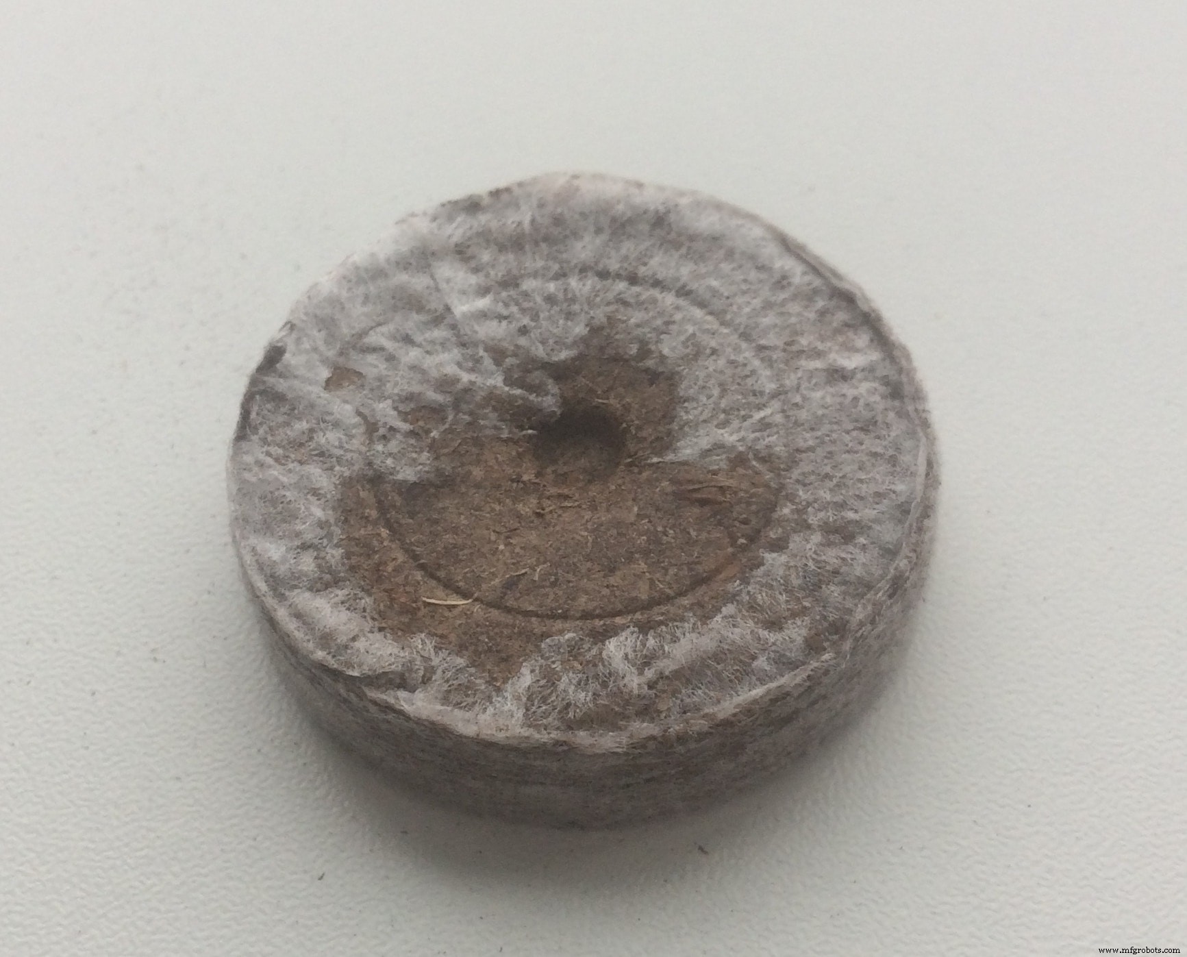
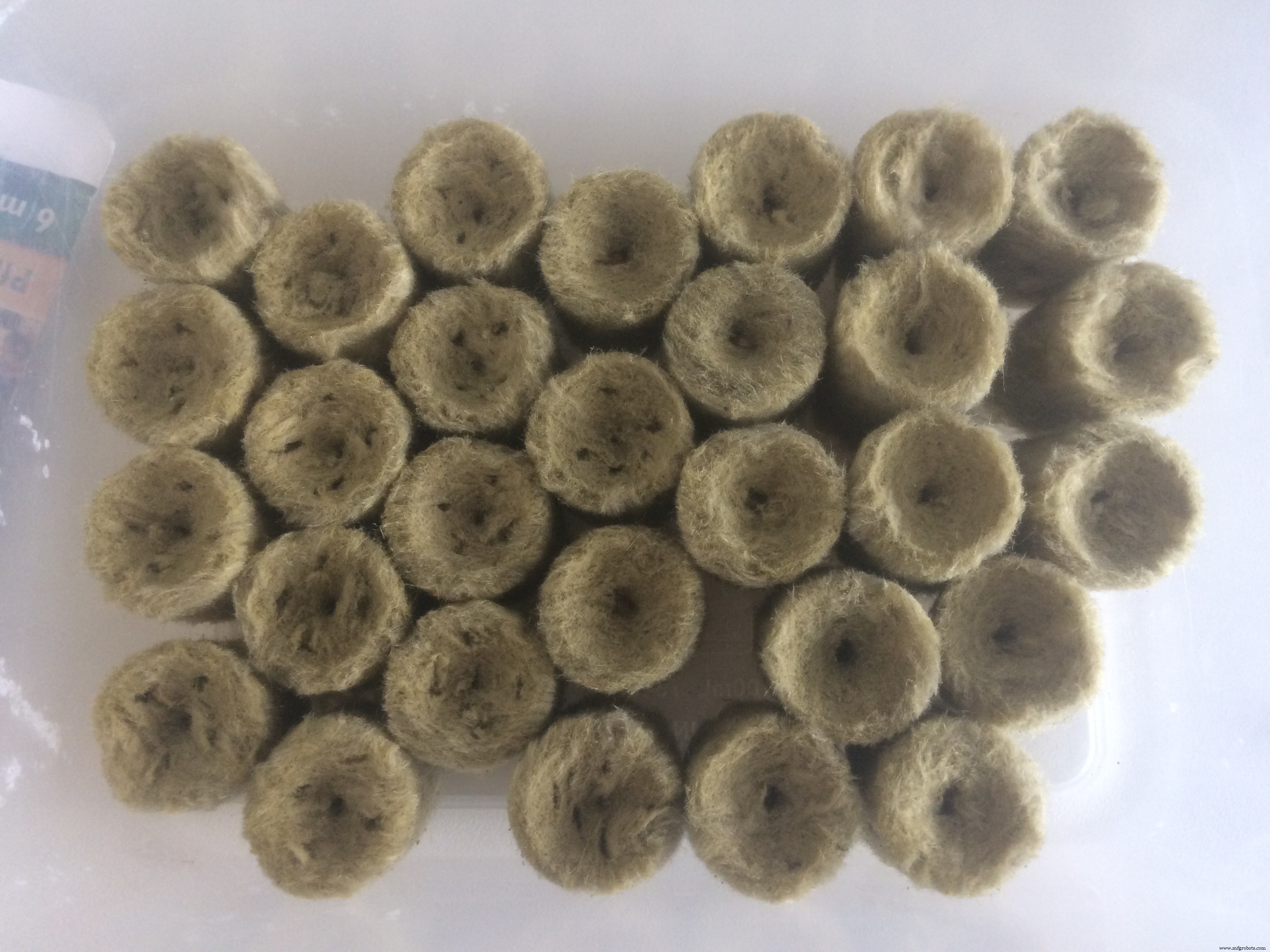
Dans le tutoriel que je suivais (blogueur YouTube), le gars a recommandé de planter les petites plantes dans n'importe quel type de support, jusqu'à ce qu'elles donnent ce qu'on appelle des "secondes feuilles". Sur Amazon j'ai commandé des granulés de coco coco . Ils sont organiques, ont des propriétés similaires à celles du sol, et ce qui est cool, c'est que lorsque les granulés sont arrosés, ils deviennent 6 fois plus gros.
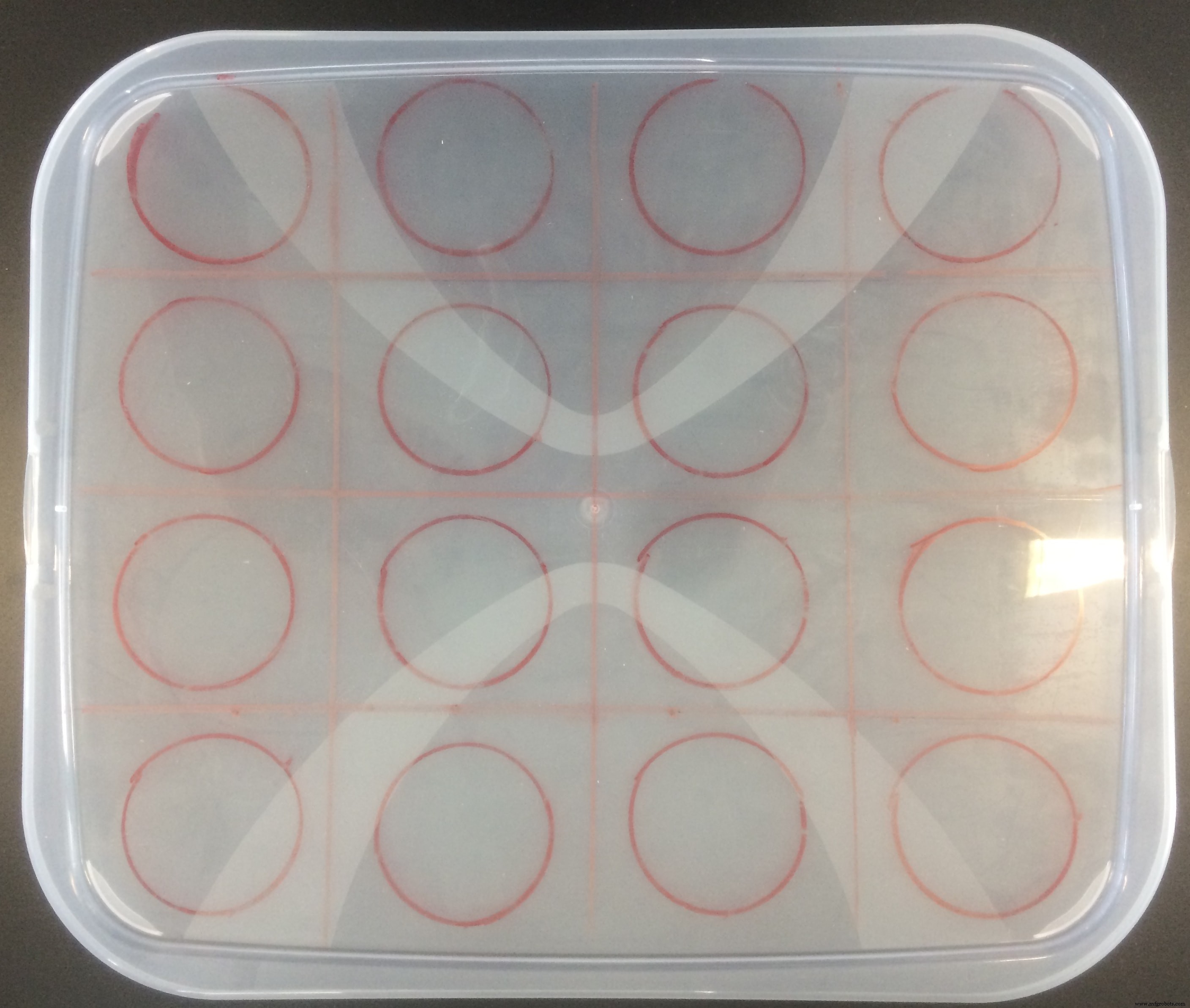
J'ai aussi acheté une boîte, qui a des séparateurs spécialement pour la plantation ! Je l'ai eu pour seulement 2 euros, et cela a rendu les choses beaucoup plus organisées. J'ai placé les boulettes de noix de coco à l'intérieur des séparateurs de la boîte, je les ai arrosées jusqu'à ce qu'elles soient complètement hydratées, j'ai placé les petites plantes au milieu et j'ai recouvert la boîte d'un morceau de plastique transparent fourni avec le kit de la boîte.
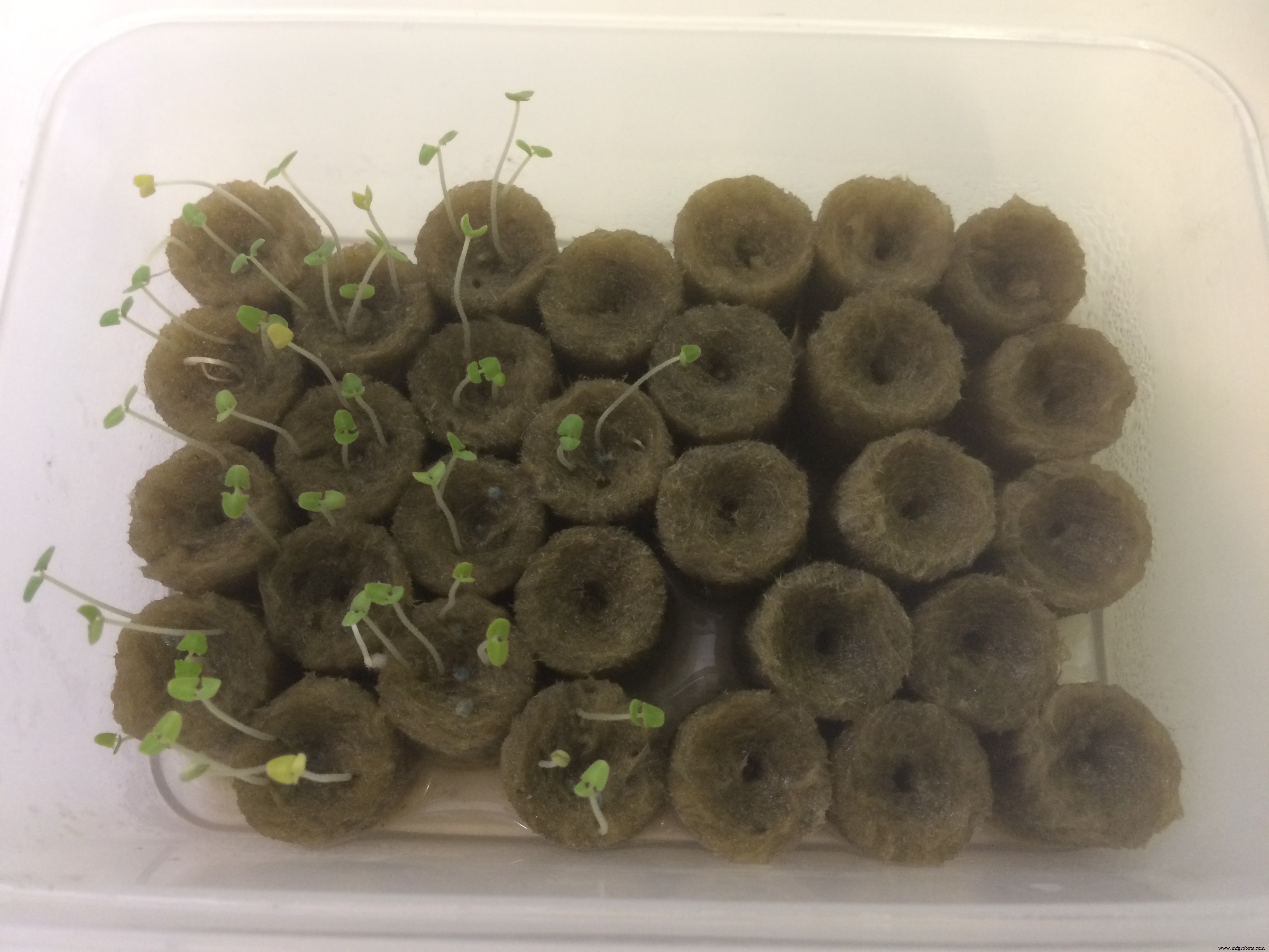
Ma petite serre ressemblait à ceci :
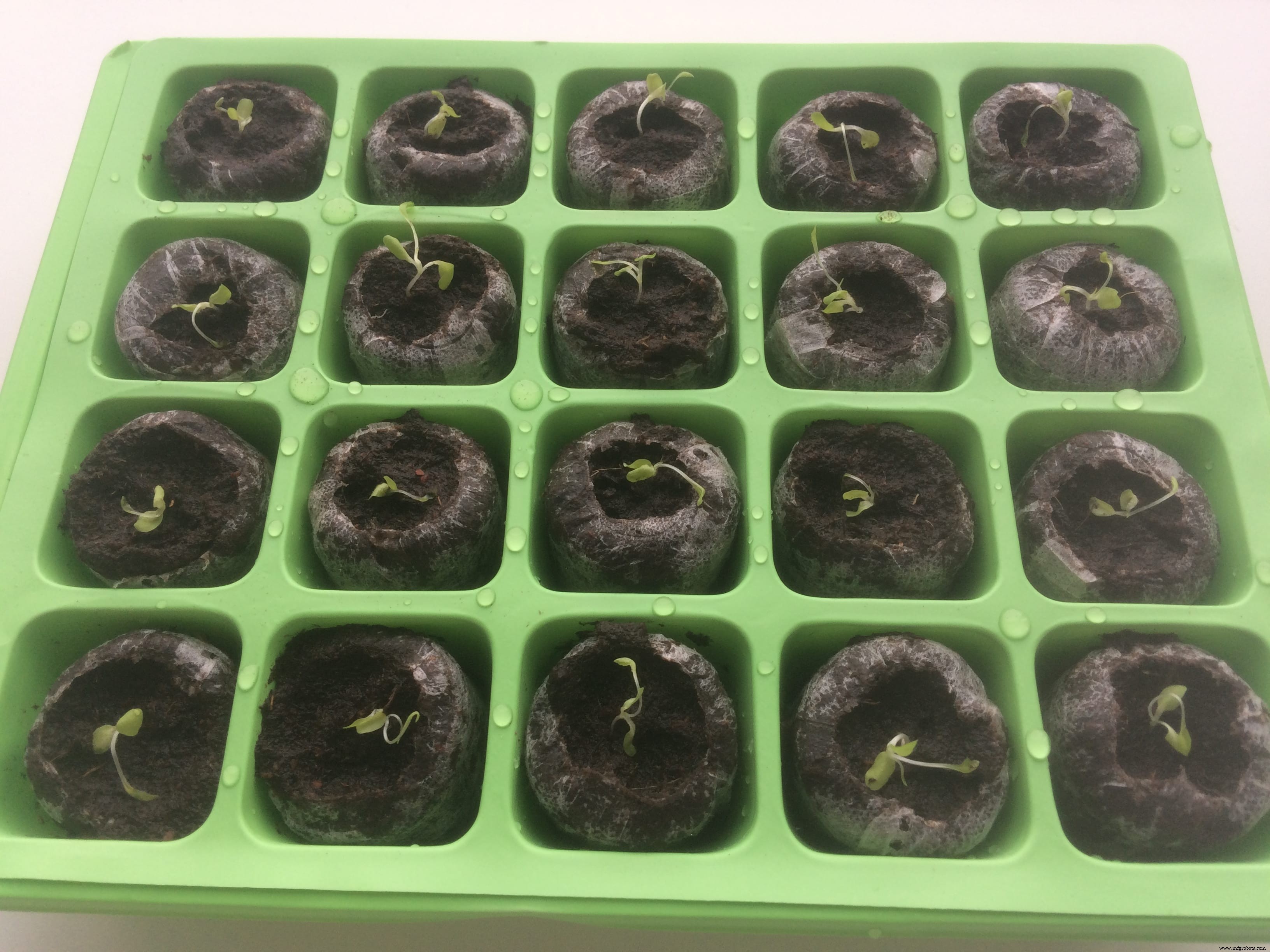
J'ai fermé la boîte et je l'ai laissée une semaine !
Et encore une fois quand je l'ai ouvert, j'ai été surpris ! En fait, ils sont devenus plus gros ! Je n'aurais jamais pu imaginer pouvoir faire pousser des plantes, j'arrive à peine à prendre soin de moi :D
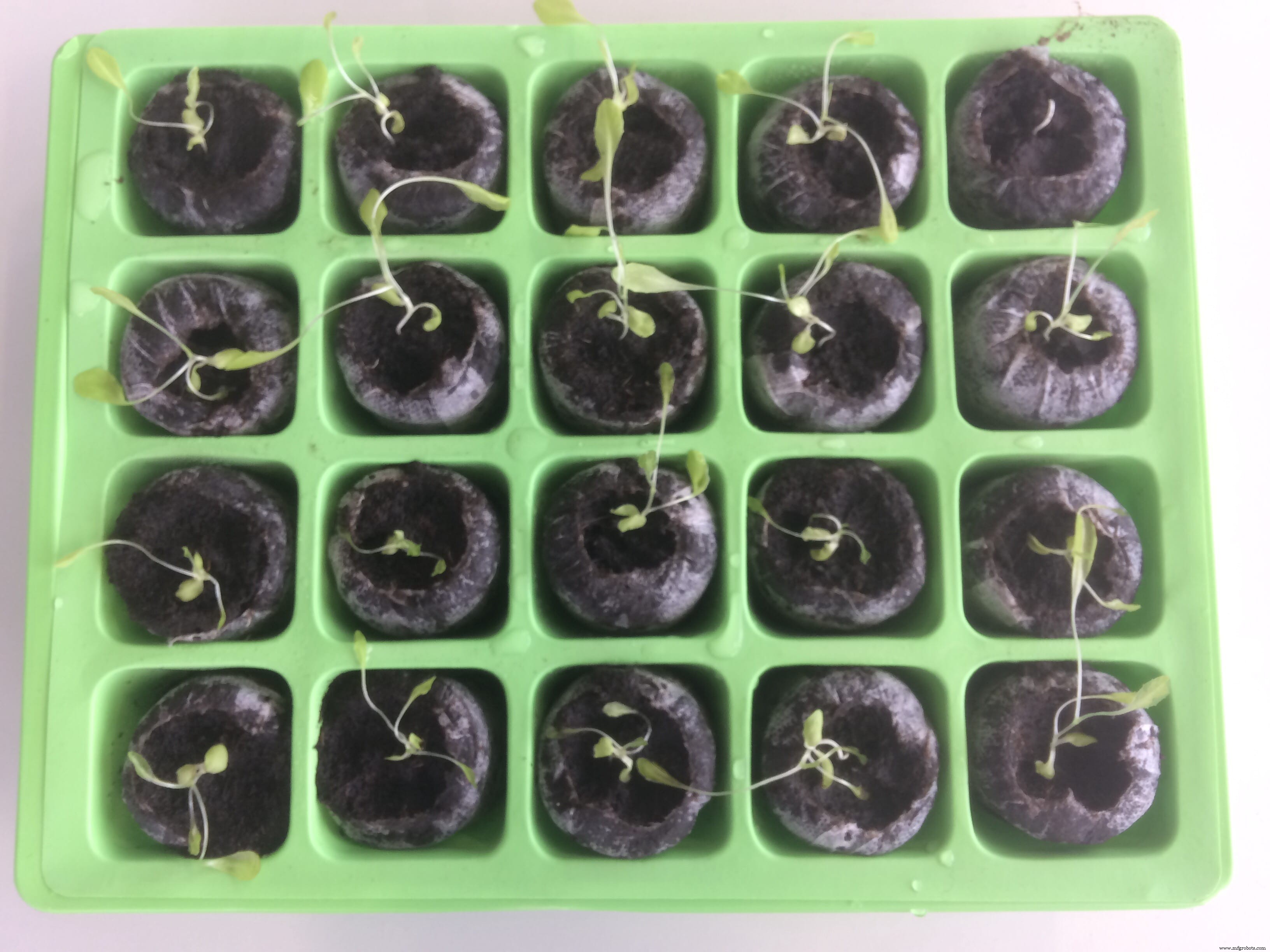
Au bout d'une semaine, la différence est notable !
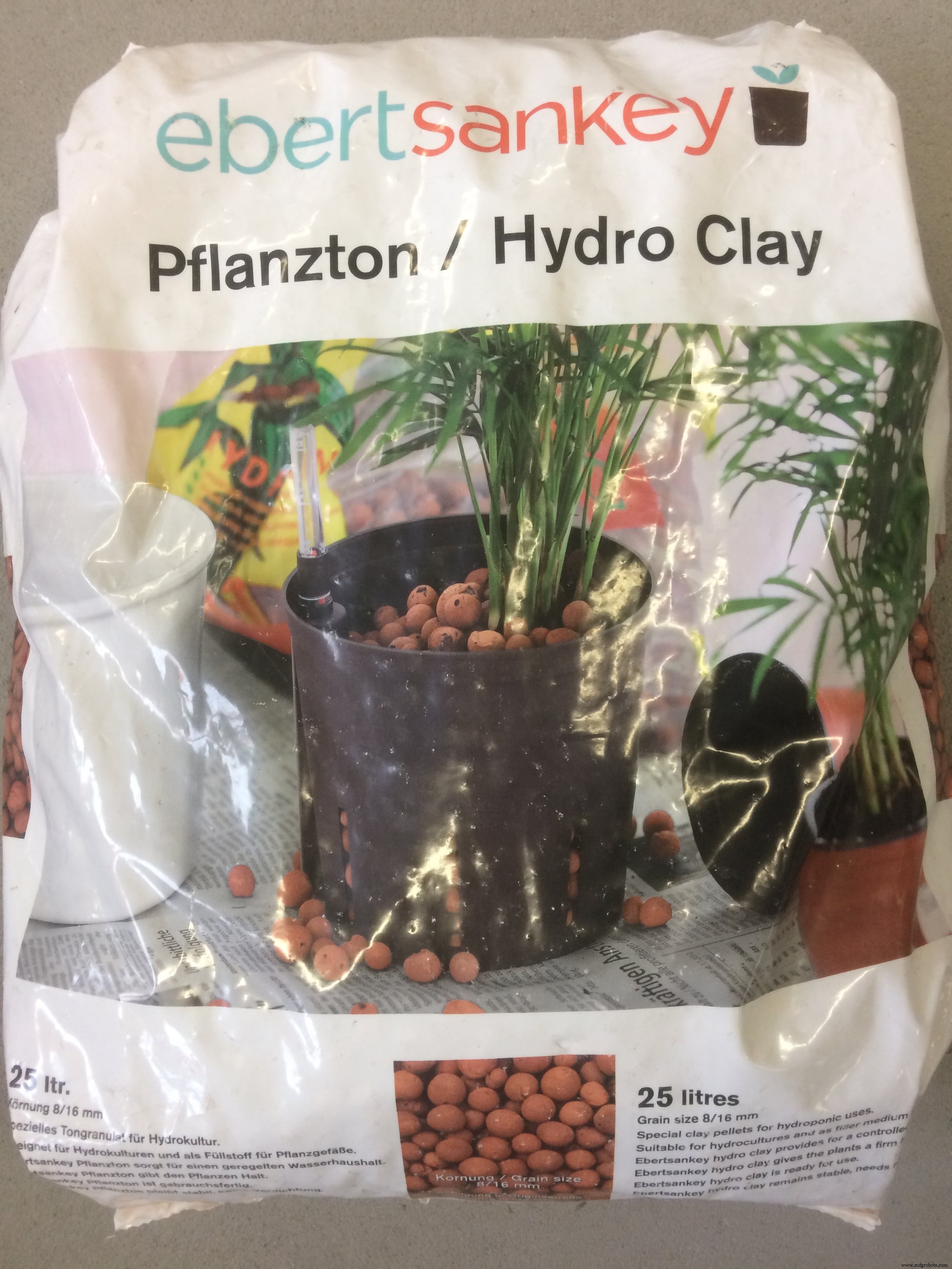
Maintenant, quand je vois les premières racines, je peux les placer dans de la terre et des boules d'argile, et commencer à expérimenter avec le brouillard !
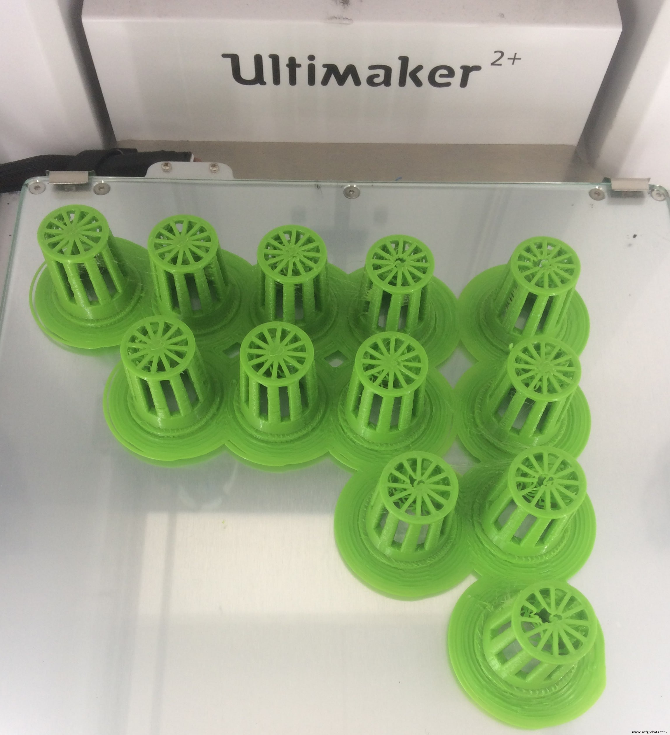
Pendant la semaine de Conception Assistée par Ordinateur, j'ai conçu les coupelles en filet, que j'ai utilisées pour placer les plantes
J'ai également acheté dans un magasin local un récipient en plastique avec les dimensions approximatives dont j'ai besoin, et esquissé les trous à percer !
Et voici mon système de test assemblé, avec les plantes à l'intérieur des boulettes de noix de coco, et des boules d'argile, ainsi que de la terre !
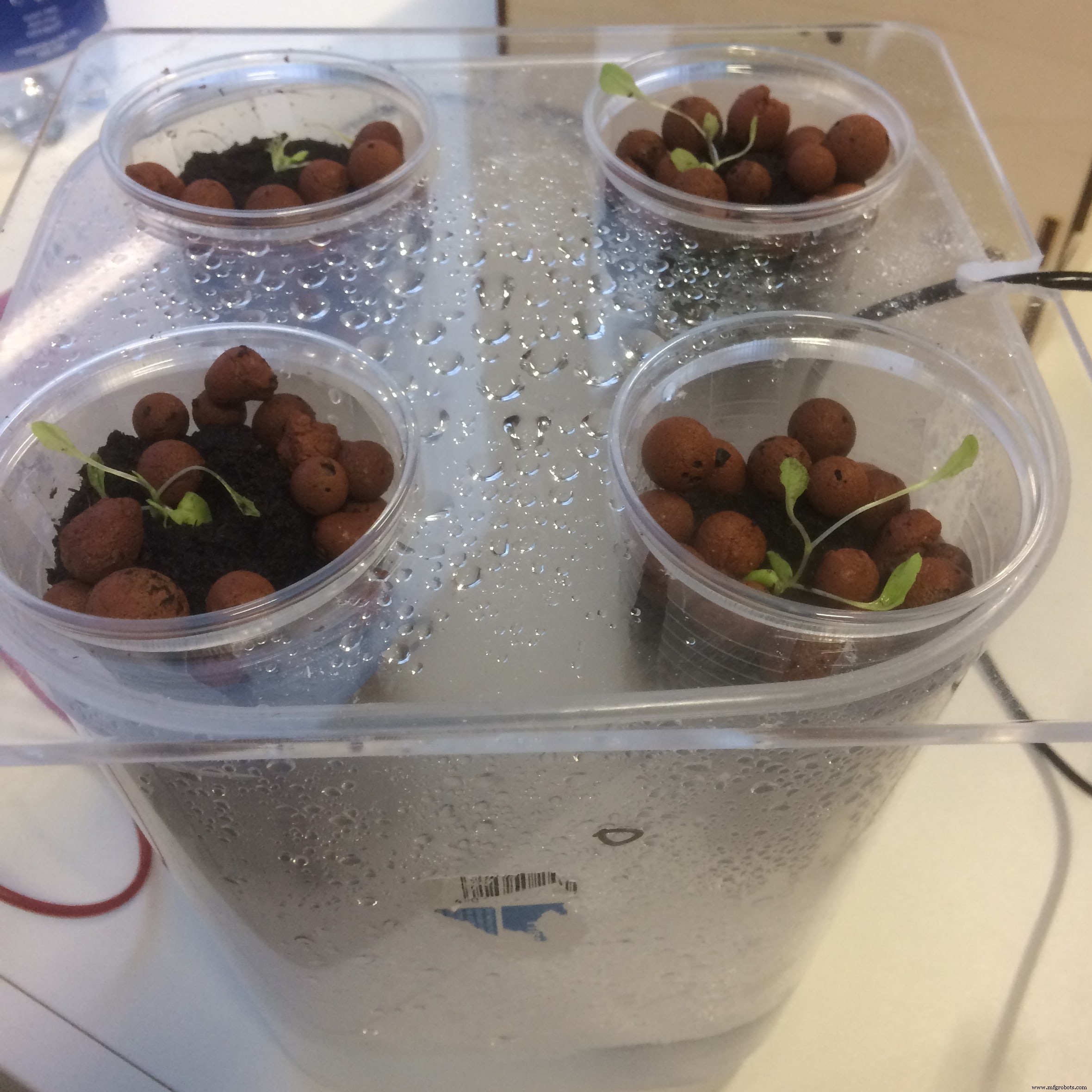
Pour être honnête, les résultats pourraient être meilleurs :D
Seules quelques plantes ont survécu dans mon système de brouillard. Je suppose que c'est à cause du milieu de culture ! Le brouillard n'est pas assez fort pour garder les boules d'argile humides, ni le sol.
Pâques !
Pendant les vacances de Pâques, je n'ai rien fait, et comme le laboratoire était fermé, tout le système était également éteint. Donc, mes plantes sont toutes mortes
Avec un esprit frais, j'ai décidé de faire un autre système, mais cette fois en utilisant un autre milieu de culture basé sur les observations précédentes
Le substrat de culture que j'ai choisi pour ce système est la Laine de roche . Je l'ai acheté dans notre magasin IKEA local. J'ai aussi acheté quelques graines de leur département

Et j'ai placé les nouvelles graines dans la laine de roche pour la germination pendant une semaine !
Au bout d'une semaine, j'ai coché ma case et j'ai remarqué qu'un type de graines avait réussi, un autre a échoué ! Faute de temps, j'ai continué avec les graines qui ont germé
En attendant, j'ai mis en place un autre système de brouillard, et je vais essayer d'augmenter son temps de travail, pour voir si je peux faire germer des graines avec du brouillard, UNIQUEMENT DU BROUILLARD !
Je vais continuer à expérimenter avec différents paramètres et réglages, et voir jusqu'où je peux aller !)
Conception et production électronique
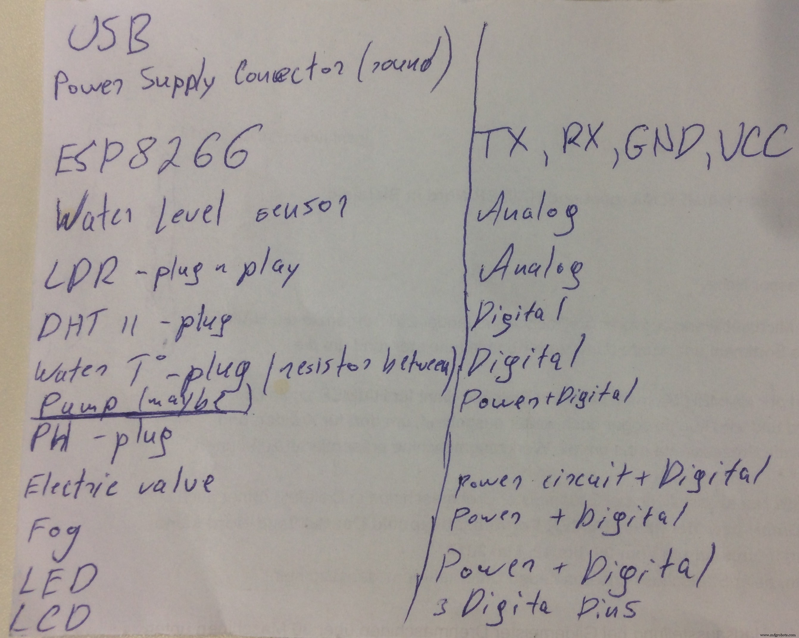
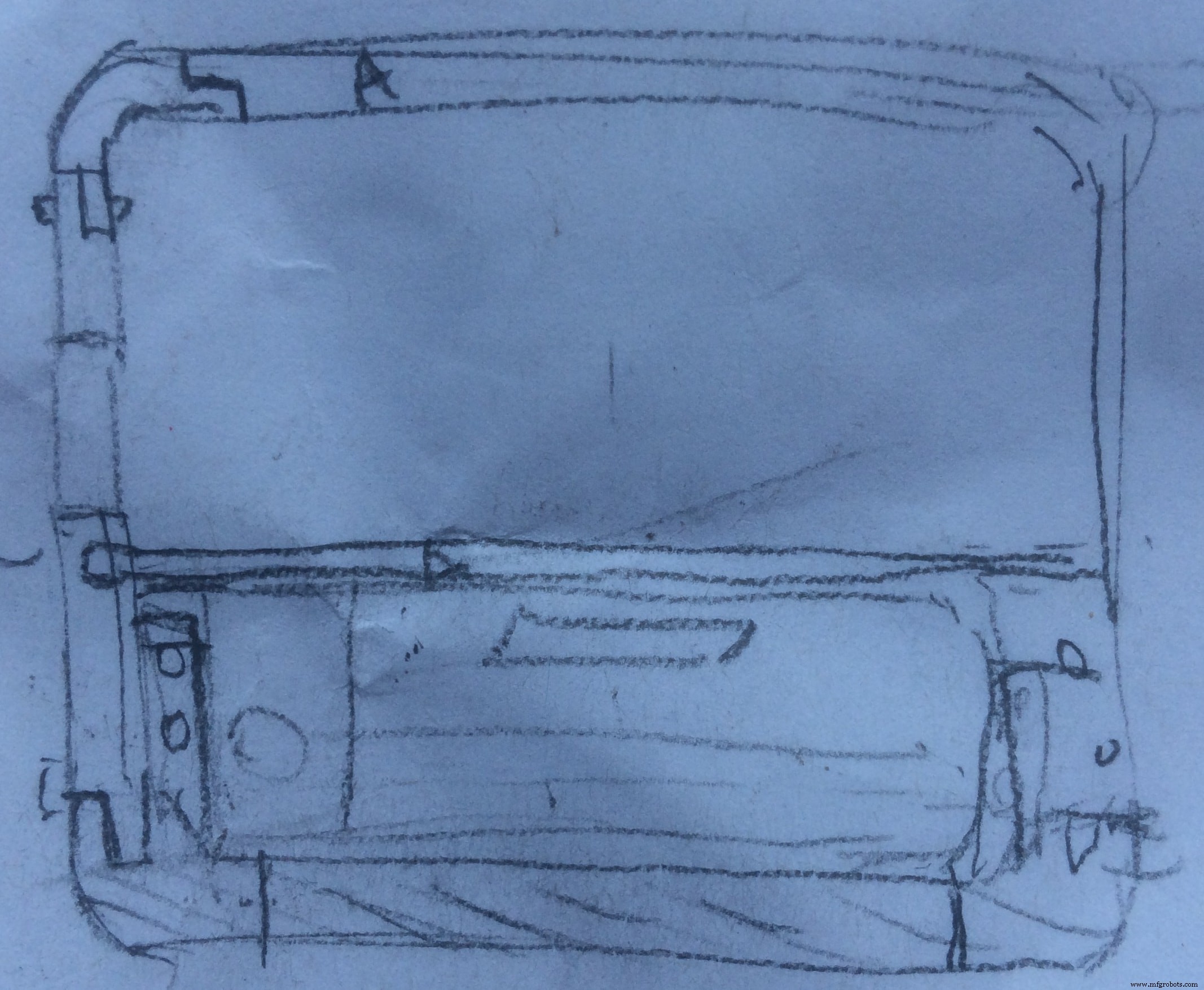
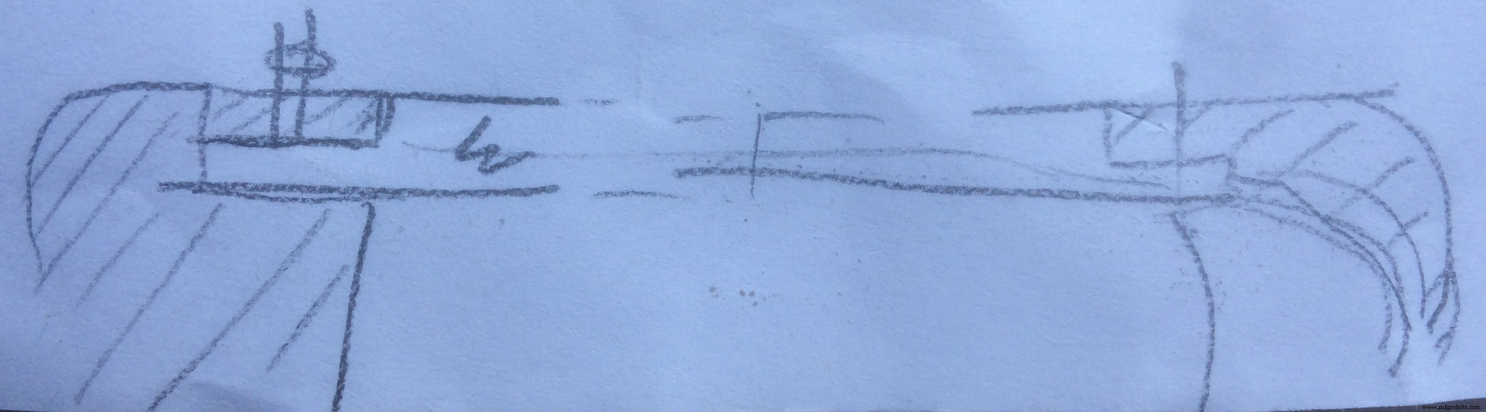
Avant de me lancer dans la conception du tableau final, je me suis assis pour dessiner sur un morceau de papier toutes les fonctionnalités et exigences que le tableau doit mettre en œuvre et remplir ! Je garde également une trace du nombre de broches qui vont être utilisées, afin de mieux estimer et décider quel sera le microprocesseur final
Voici le croquis de ce qui devrait être au tableau :
Le choix final sur la carte à utiliser était entre satshakit de Daniele Ingrassia et FABLEO par Jonathan Grinham
satshakit est une carte 100% compatible Arduino IDE et bibliothèques, fabbable et open source, ainsi qu'une version améliorée de Fabkit.
Les principales améliorations et fonctionnalités par rapport à Fabkit sont :
- 16Mhz au lieu de 8Mhz
- cristal au lieu de résonateur
- coûte moins cher (7-9 euros contre 13 euros)
- 100% compatible avec l'IDE Arduino par défaut (satshakit est reconnu comme Arduino UNO)
- ADC6/7 connecté au lieu d'ADC6/7 non connecté (laser satshakit et cnc)
- espace plus grand pour une soudure facile (laser satshakit et cnc)
En revanche, le FabLeo a des fonctionnalités très similaires, en plus du matériel USB ! Comme j'utilisais déjà l'ATmega328p plus tôt, je voulais essayer quelque chose de nouveau et j'ai décidé d'utiliser le design FabLeo comme point de départ
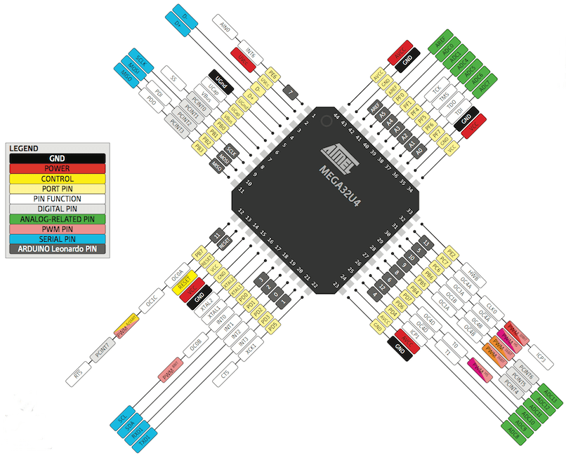
Ma bible et le guide n°1 pour cette tâche était le brochage ATmega32u4
Pour concevoir la carte, le logiciel que j'utiliserai pour cela est EAGLE (Easly Applicable Graphical Layout Editor) est un programme flexible et extensible de capture schématique EDA, de mise en page PCB, d'autorouteur et de FAO. EAGLE est populaire parmi les amateurs en raison de sa licence de logiciel gratuit et de la grande disponibilité de bibliothèques de composants sur le Web.
Eagle a deux fenêtres qui sont utilisées simultanément pour concevoir une planche :
- Schéma (.sch) - composants logiques
- Mise en page du tableau (.brd) pour la planche que nous fraisons
Après avoir installé EAGLE, la première chose que je veux faire est de Créer un nouveau schéma . Un schéma en électronique est un dessin représentant un circuit. Il utilise des symboles pour représenter des composants électroniques du monde réel. Le symbole le plus basique est un simple conducteur (traces), représenté simplement par une ligne. Si les fils se connectent dans un schéma, ils sont indiqués par un point à l'intersection.
Afin de placer mes composants sur les schémas, je dois télécharger et utiliser des Bibliothèques spéciales . Eagle a beaucoup de bibliothèques intégrées de composants que nous pouvons utiliser. Le réseau fab maintient également une bibliothèque qui est constamment mise à jour :
fab.lbr
Pour installer la bibliothèque, dans l'environnement EAGLE, allez dans la barre d'outils supérieure et sélectionnez la Bibliothèque menu. Sélectionnez ensuite utiliser et ouvrez le .lbr fichier que je viens de télécharger.
Maintenant, je peux aller à Ajouter un composant et en sélectionnant la bibliothèque, je choisis le composant que je veux placer.
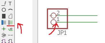
Lorsque j'ai placé tous les composants sur mes schémas, je dois connecter chacun d'eux aux broches du microprocesseur. Dans le menu de gauche EAGLE, je clique sur Net , commande qui me permet de tracer des lignes vertes et de connecter les broches. L'important est de démarrer la connexion à partir du petit trait sur la broche (je l'ai marqué sur la photo)
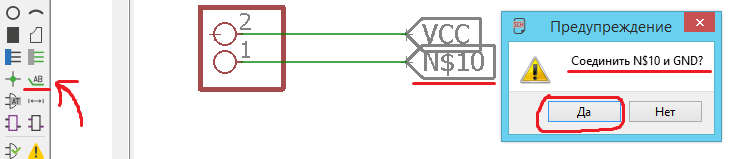
Pour éviter plusieurs connexions, j'utiliserai des étiquettes. . Dans le menu de gauche d'EAGLE, j'appuie sur Ajouter une étiquette et l'ajouter à la fin de ma ligne de connexion. Si j'appuie sur le clic droit puis choisissez nom , je peux attribuer à l'étiquette le même nom que j'ai utilisé pour la broche du microprocesseur, et les connecter de cette manière !
Si j'ai tout fait correctement, un message devrait apparaître :Êtes-vous sûr de vouloir connecter votre étiquette (10 $N) avec GND ?
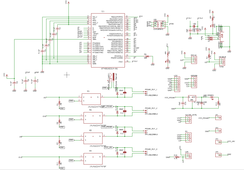
A ce stade, dans la chimie, l'important est la Logique de toutes les connexions, pas à quoi il ressemble. Après avoir fini de placer tous les composants et de les avoir connectés de manière logique, voici à quoi cela ressemble :
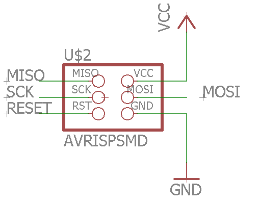
J'ai ajouté l'AVRISP têtes d'épingle, et les a placés dans l'ordre approprié pour le connecteur. Ces broches seront utilisées pour programmer ma carte.
Voici les schémas de l'USB circuit avec le cristal
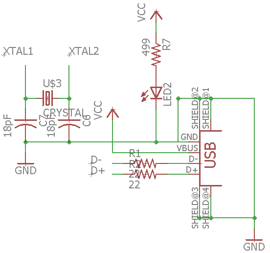
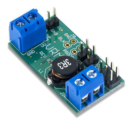
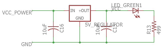
J'ai également ajouté un régulateur de tension circuit qui alimentera toute la carte en transformant l'entrée 12V en 5V
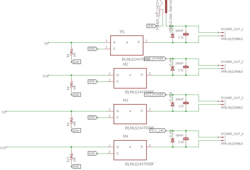
L'une des caractéristiques importantes de cette carte est le MOSFET circuits, j'en ai ajouté 4, 3 connectés directement à l'entrée (12V), et un sera connecté à un régulateur de tension élévateur. Le dernier servira à alimenter le brouillard qui fonctionne en 24V
Après avoir revérifié toutes les connexions, je peux passer à l'étape suivante, qui est la mise en page du tableau . Dans le menu du haut, j'appuie sur Generate/Switch to Board .
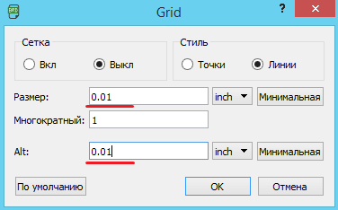
La première chose que je fais est d'augmenter la Grille résolution. Je vais dans Afficher menu, et appuyez sur Grille , et remplacez les valeurs par 0.01 . Cela me permettra d'être plus précis lors du tracé des lignes de route.
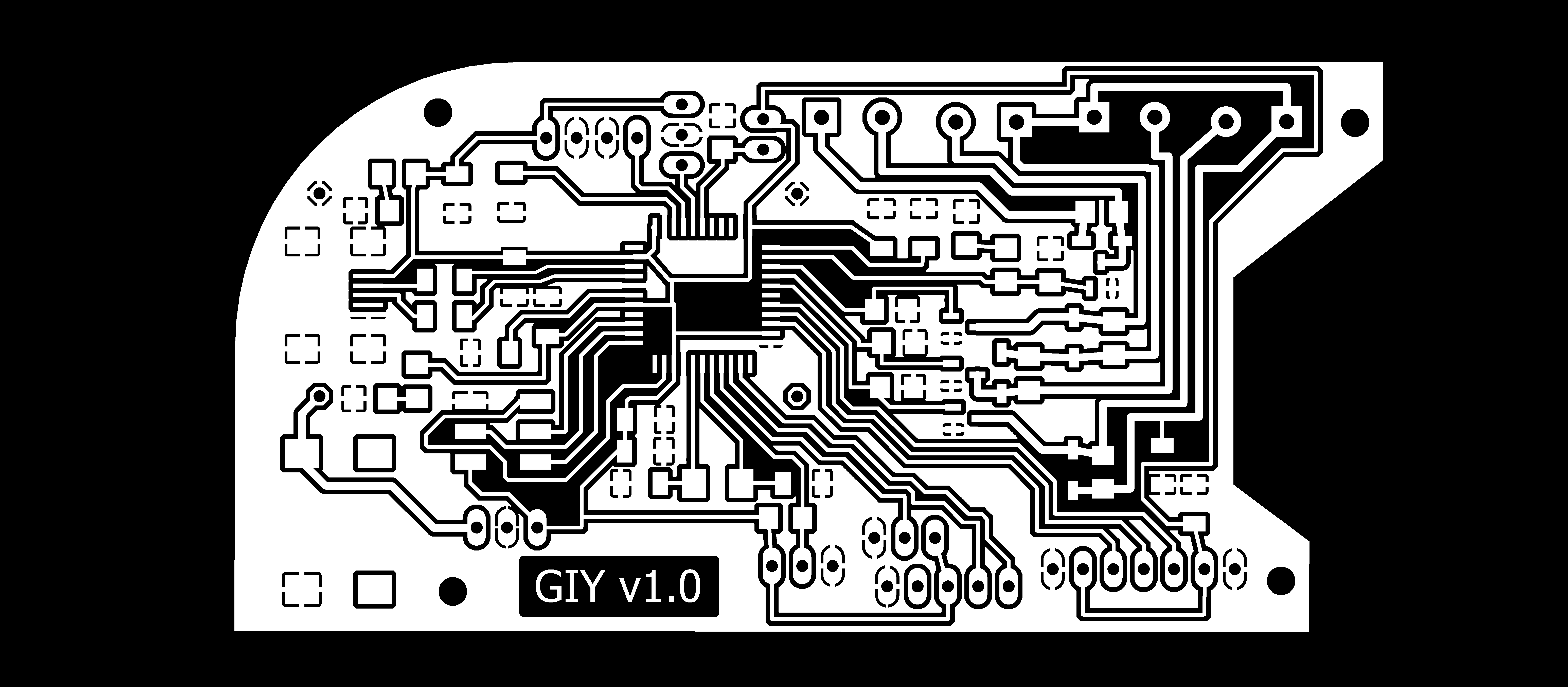
Étonnamment, le routage de la planche la plus complexe que j'ai faite jusqu'à présent était aussi le plus rapide !) Je suis fier de moi. L'expérience de la fabrication de planches a eu une bonne influence sur l'amélioration de la vitesse. Une fois le routage terminé, voici à quoi ressemble la petite bête :
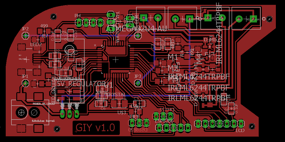
Pour cette planche, j'utilise aussi le truc que j'ai appris plus tôt. Je dessine un polygone autour de mes composants, et en appuyant sur le clic droit sur la ligne polygonale, je change le nom en GND. Cela remplira toute la zone à l'intérieur du polygone et en fera le GND.
Cela permettra d'économiser beaucoup de temps, d'espace et d'efforts
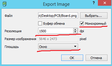
Lorsque je vérifie tout, je peux Exporter mon fichier au format .png image.
Dans la fenêtre qui apparaît, j'augmente la résolution à 1500 dpi , cliquez sur monochrome , et sélectionnez fenêtre mode.
Pour éditer l'image.png, je vais utiliser J'ouvre mon image dans GIMP , et en utilisant l'outil de sélection rectangulaire , je sélectionne l'image en laissant un peu d'espace de tous les côtés. Après avoir appuyé sur Fichier et Copier la zone sélectionnée. Pour continuer à travailler avec l'image sélectionnée, je clique à nouveau sur Fichier , et Créer à partir du presse-papiers
Voici ce que j'obtiens après toutes les modifications :
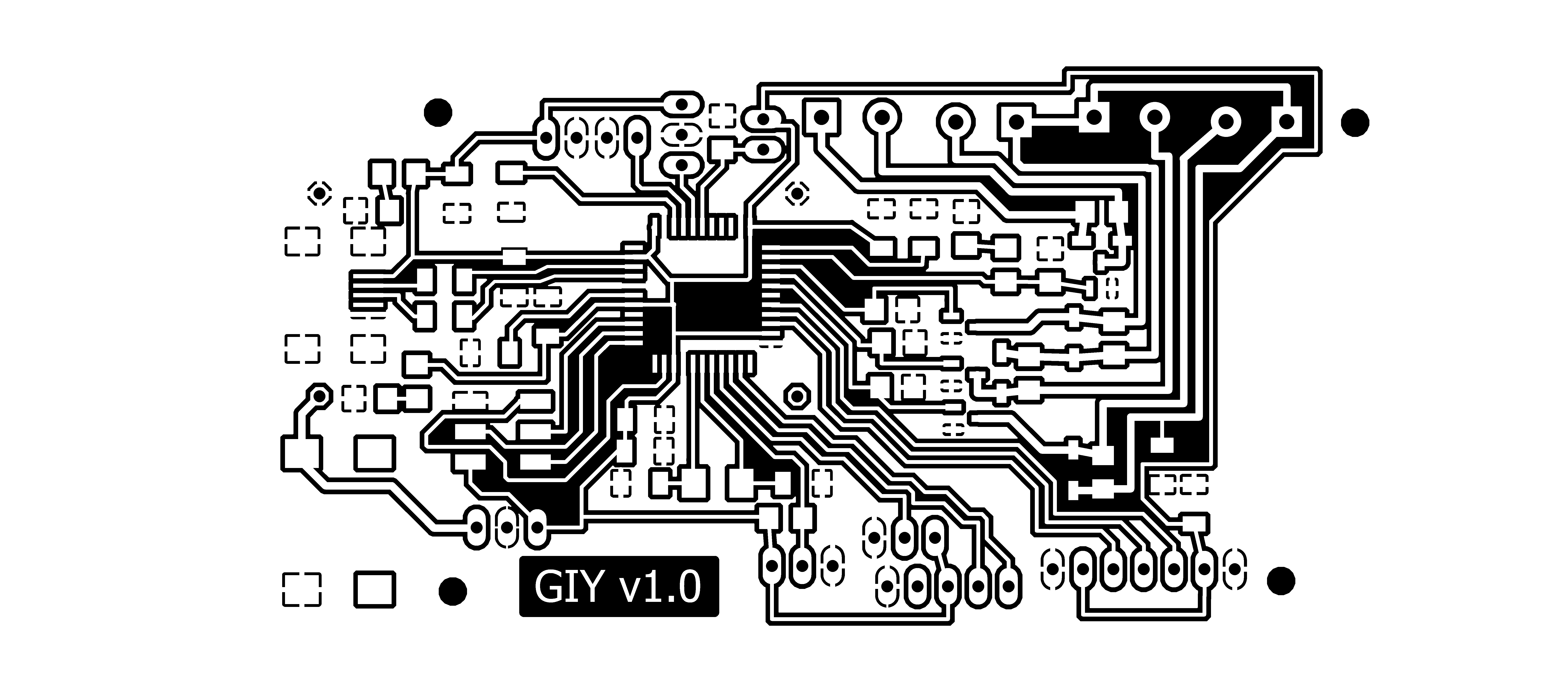
Cette image est prête à être imprimée, et je l'appellerai Inside_Cut
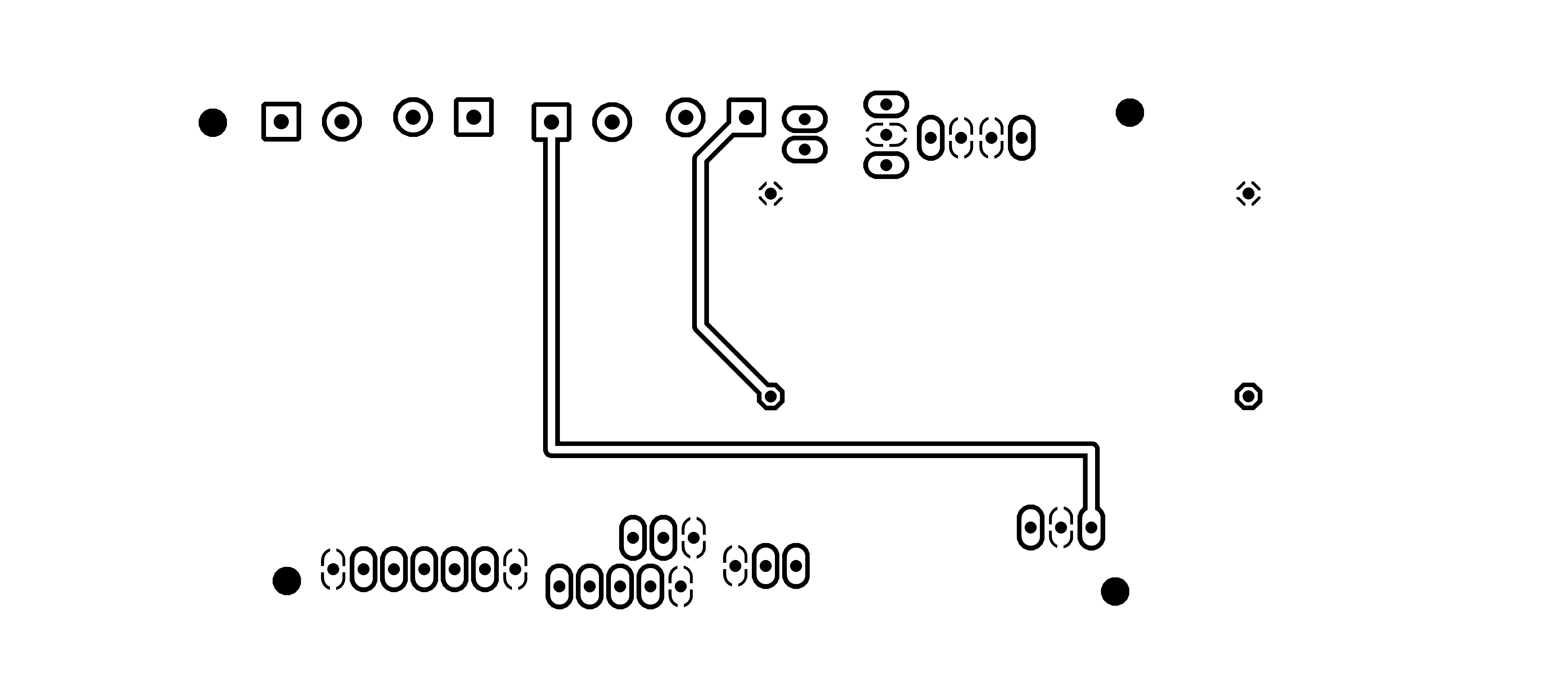
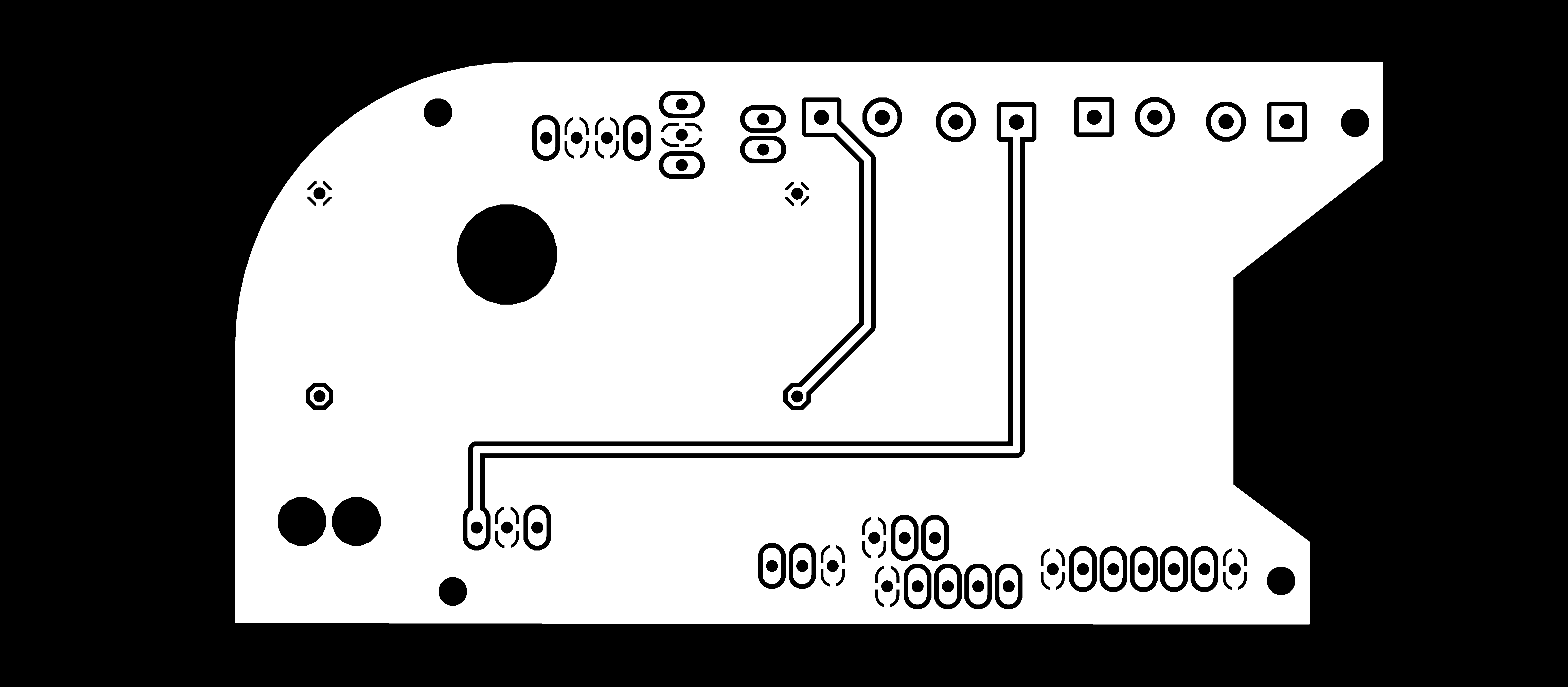
Je prépare le processus pour la Outside Cut , et voici ce que j'obtiens :

Parce que ma planche est double face, je dois fraiser deux pièces, puis les coller ensemble. La seule chose à garder à l'esprit est que la partie inférieure doit être en miroir horizontalement
Partie inférieure Inside_Cut

Partie inférieure Outside_Cut
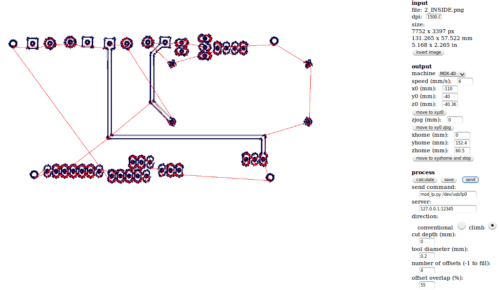
Je peux maintenant passer à la fraiseuse CNC. Donc, encore une fois, j'ai utilisé FabModules pour convertir les fichiers .PNG en Gcodes pour la machine Roland.
Commençons à travailler avec les modules Fab. Lorsque j'introduis l'adresse IP dans la fenêtre du navigateur, la première interface qui apparaît est :

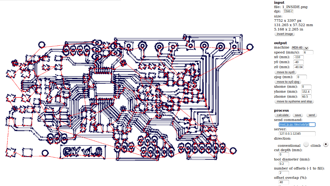
Après avoir appuyé sur le bouton gris format de saisie , un nouveau menu devrait apparaître avec la possibilité de charger l'image .PNG. Ici, je télécharge la première image, qui est la gravure intérieure. Après cela, l'aperçu de l'image apparaîtra dans les modules Fab et également d'autres champs et d'autres paramètres apparaîtront
Sur le côté droit de la fenêtre, nous avons de nombreux paramètres d'entrée. Afin de pouvoir déplacer la machine, nous devons saisir les paramètres suivants :
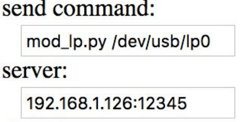
mod_lp.py /dev/usb/lp0 dans la commande d'envoi champ
hostname_of_your_machine dans le serveur field (just the address without http or /)
In order to move the machine I just enter in the respective fields the x, y and z position coordinates. Before moving the machine I have to make sure that the zjog parameter is always set to 0, even if it will change automatically. To move the machine I have to press the move to xyz0 button.
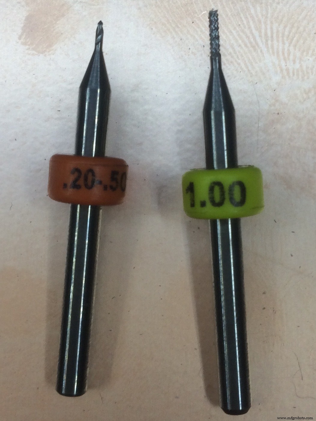
* A small life hack is to use the multimeter and check if there is connection between the tool and the surface. As a tool to engrave PCB is suggested to use diameter from 0.2 mm and below, while for cutting we can use a 1 mm tool.
So my final settings look like this:
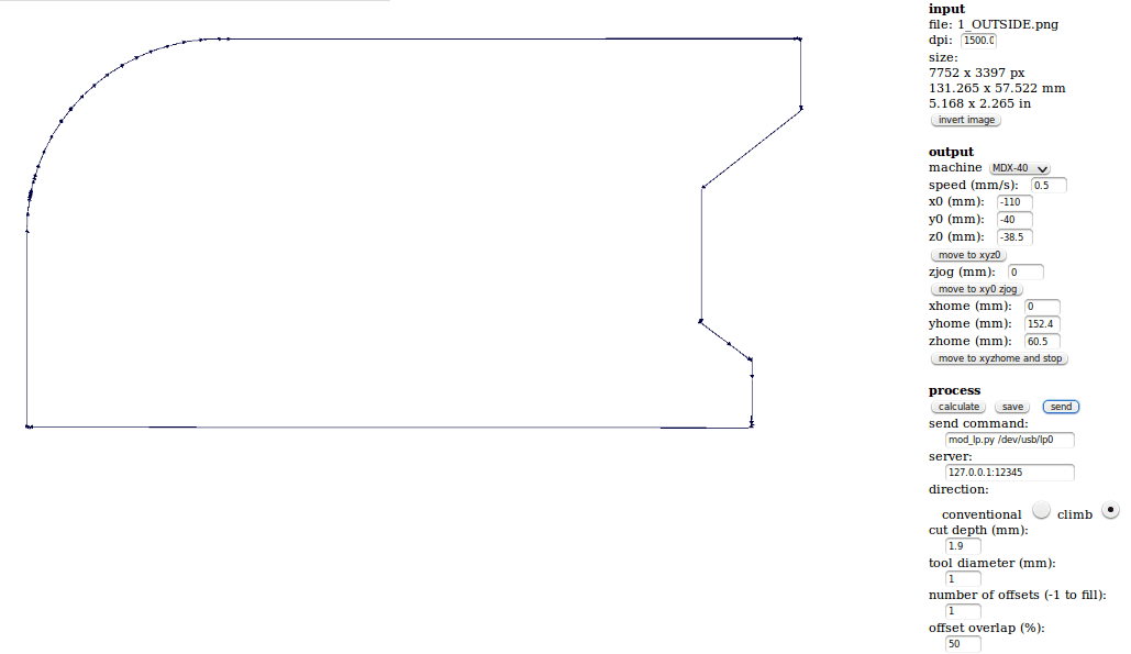
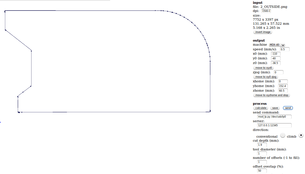
For the outside cut the settings remain the same with the exception of the value of the Z-Axis, as I replaced the 0.2mm tool with the 1mm tool. This is how it looks:
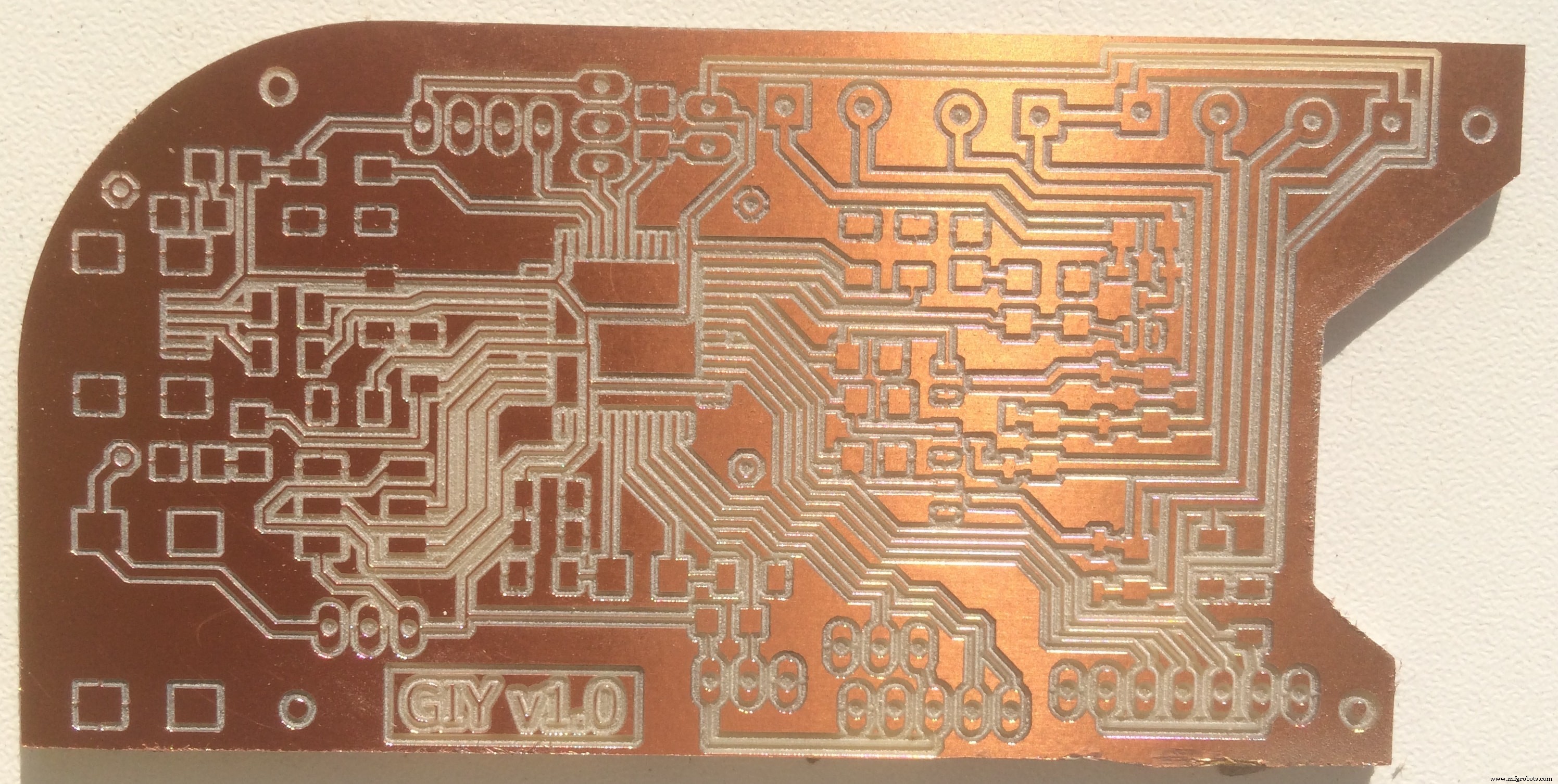
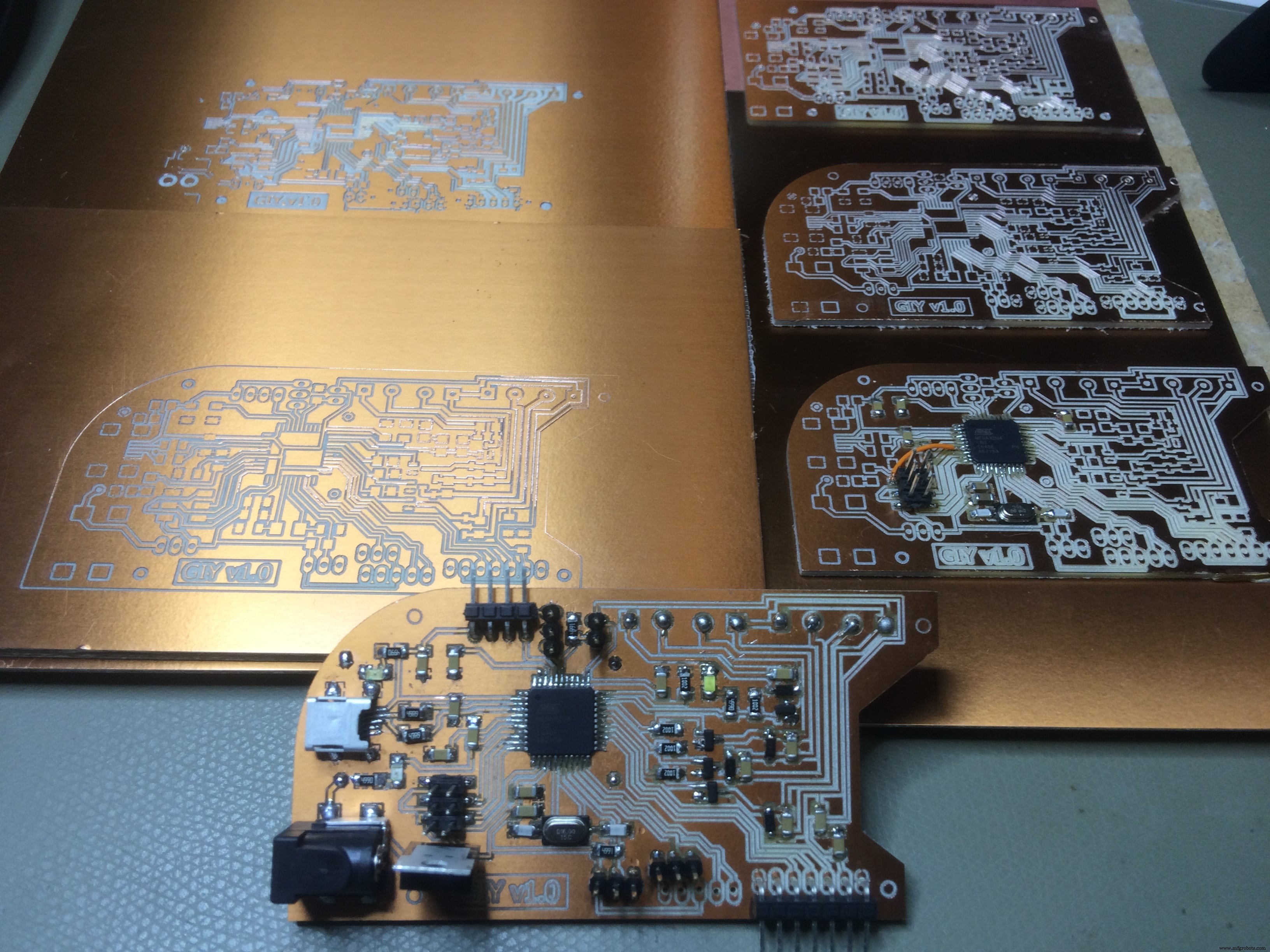
Repeat the same process for the Bottom part and mill the Inside and the Outside parts:
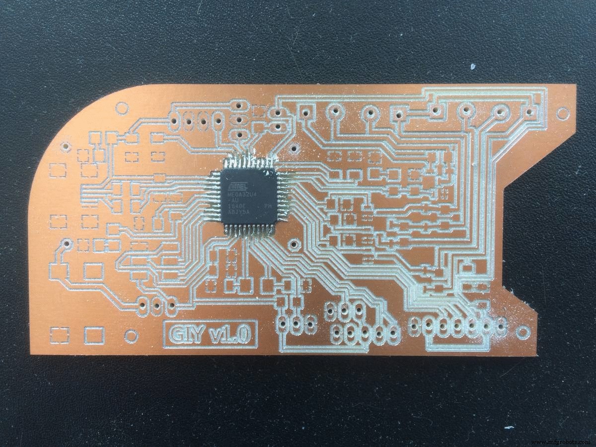
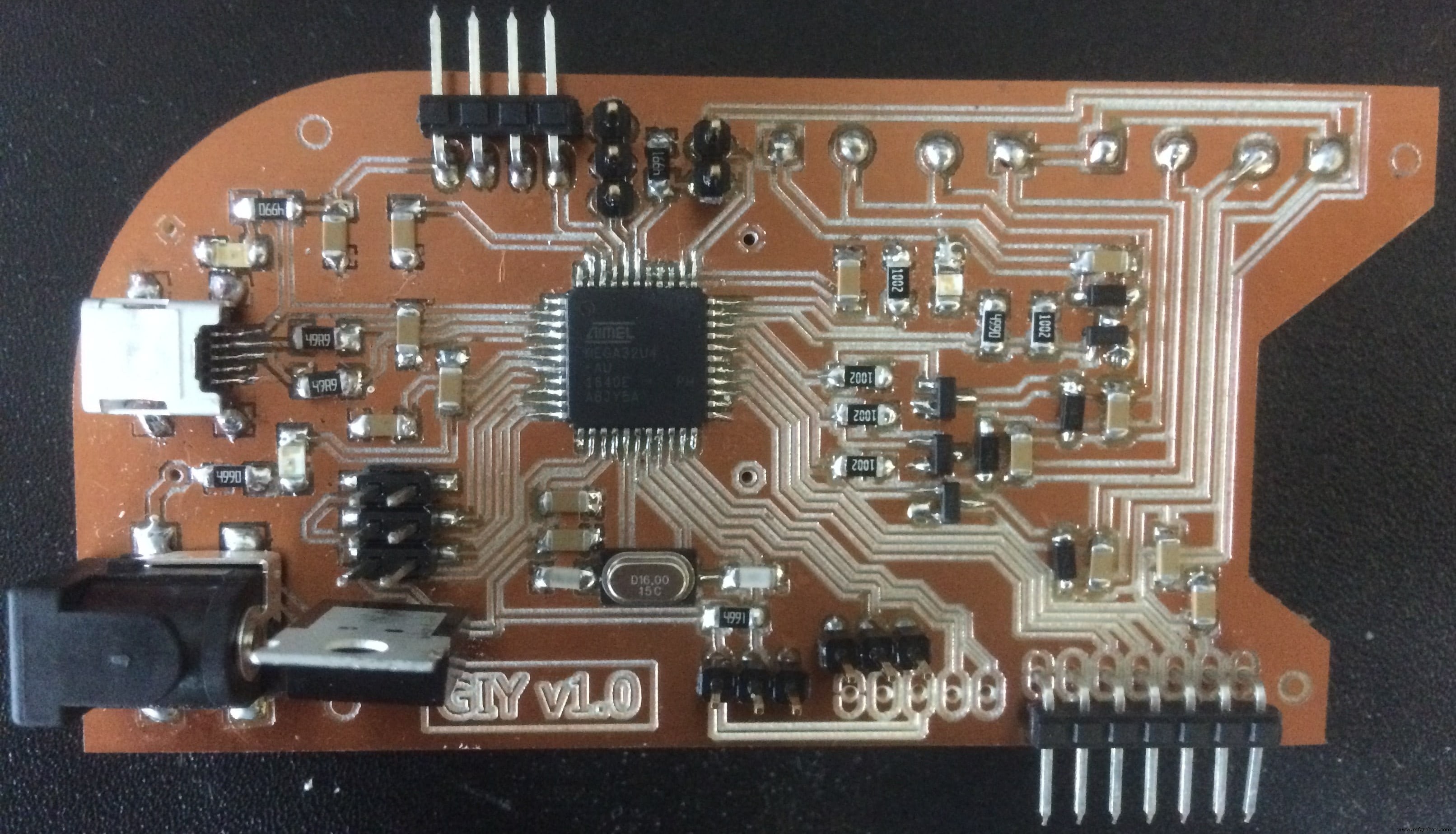
This is the final result for the Top part:
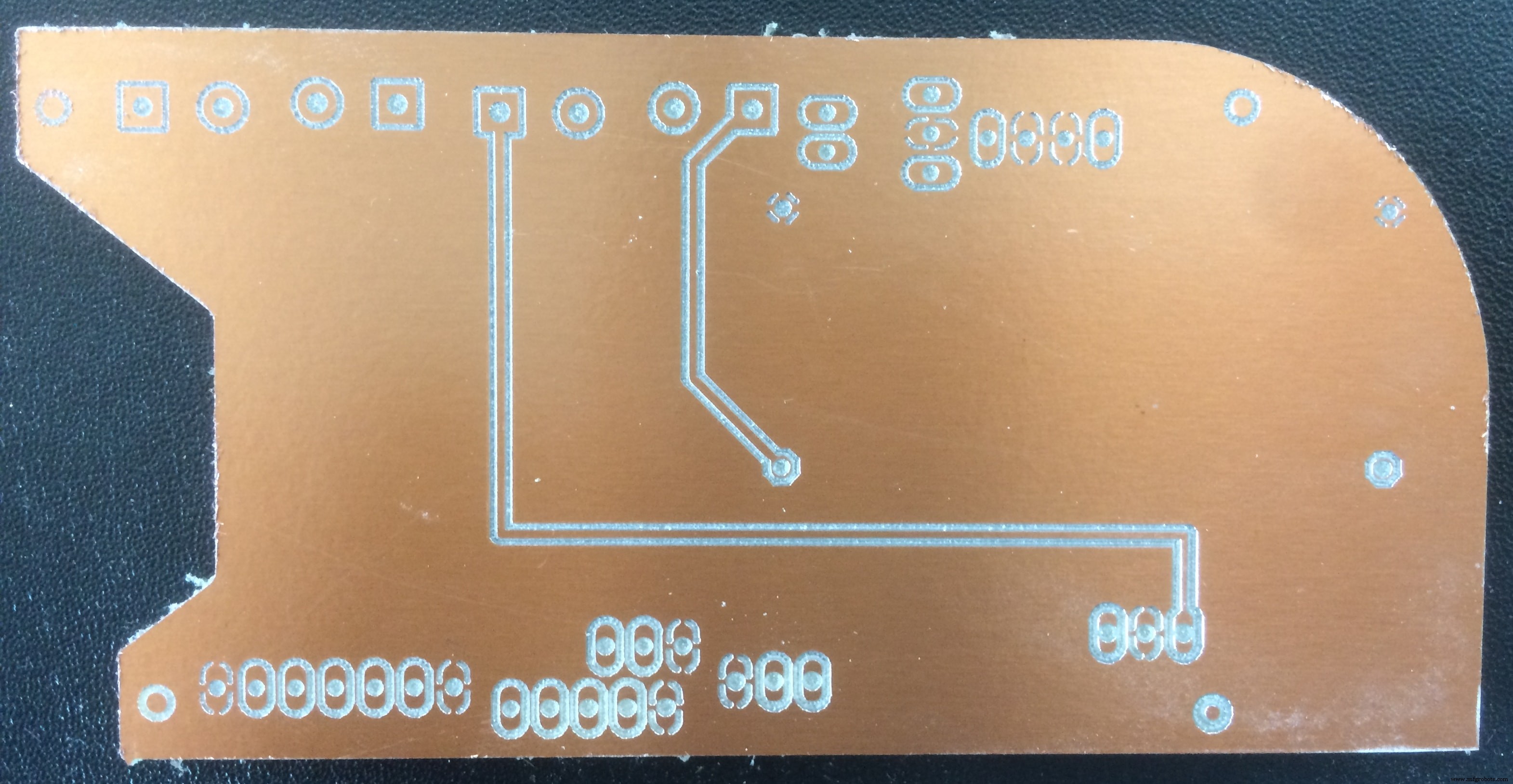
And the Bottom part:
And now Let's solder this!
In order to make sure that I soldered everything in a right way, after each component soldered, I used the multimeter to check if there is conductivity between the component and the traces.
Short animation of the process:
When I plugged in the PCB board to check if everything is fine, I noticed an error. From experience, I know that the error was from a short circuit, because the computer was disconecting the Arduino all the time I connect the VCC and GND to it. So my guess was that somewhere on the board VCC and GND are connected, and using the multimeter, I confirmed that I was right.
It was late, and I got so f*ckin' mad because of that, took me one hour under the microscope to find that little mistake. Here it is:
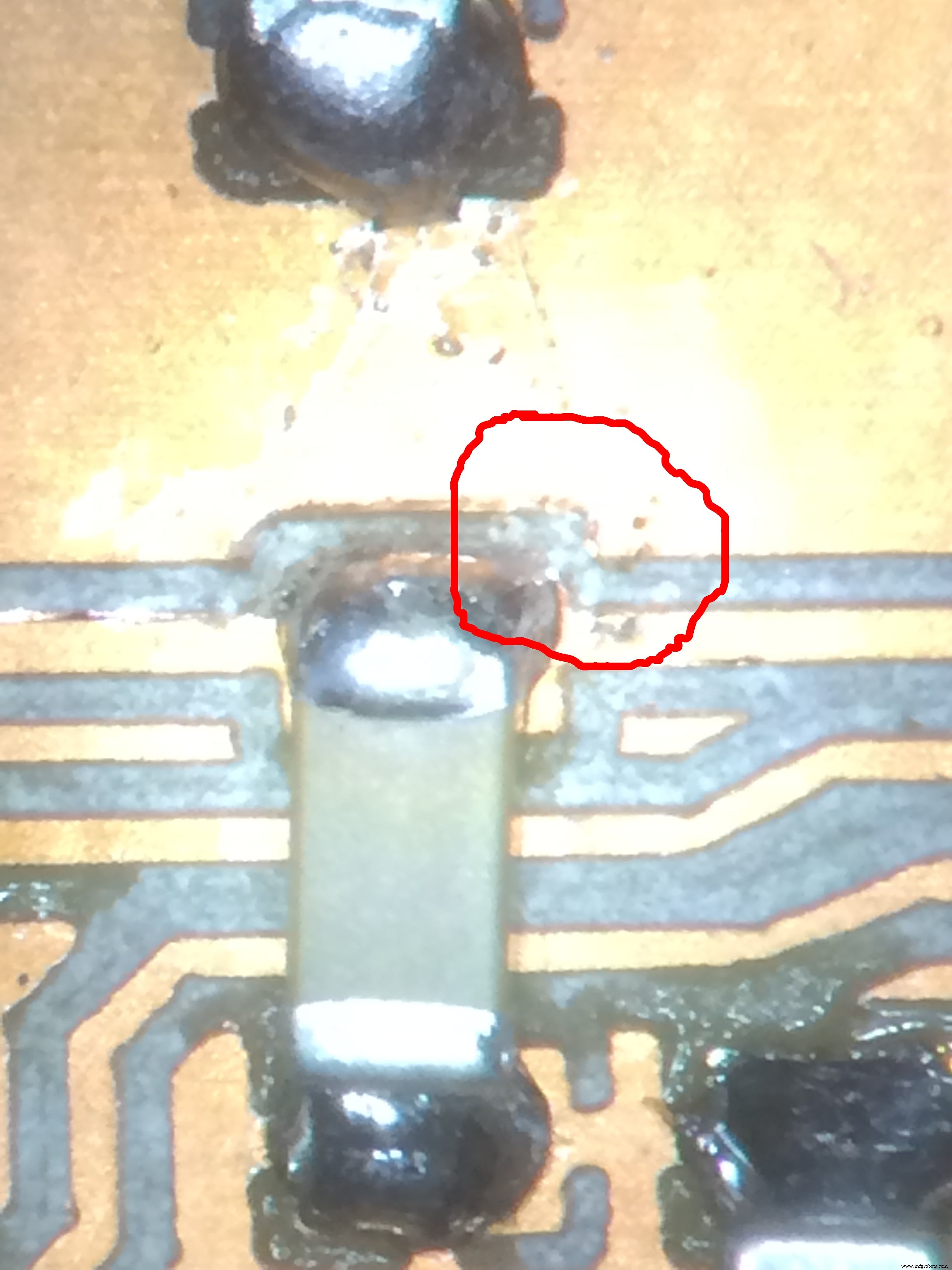
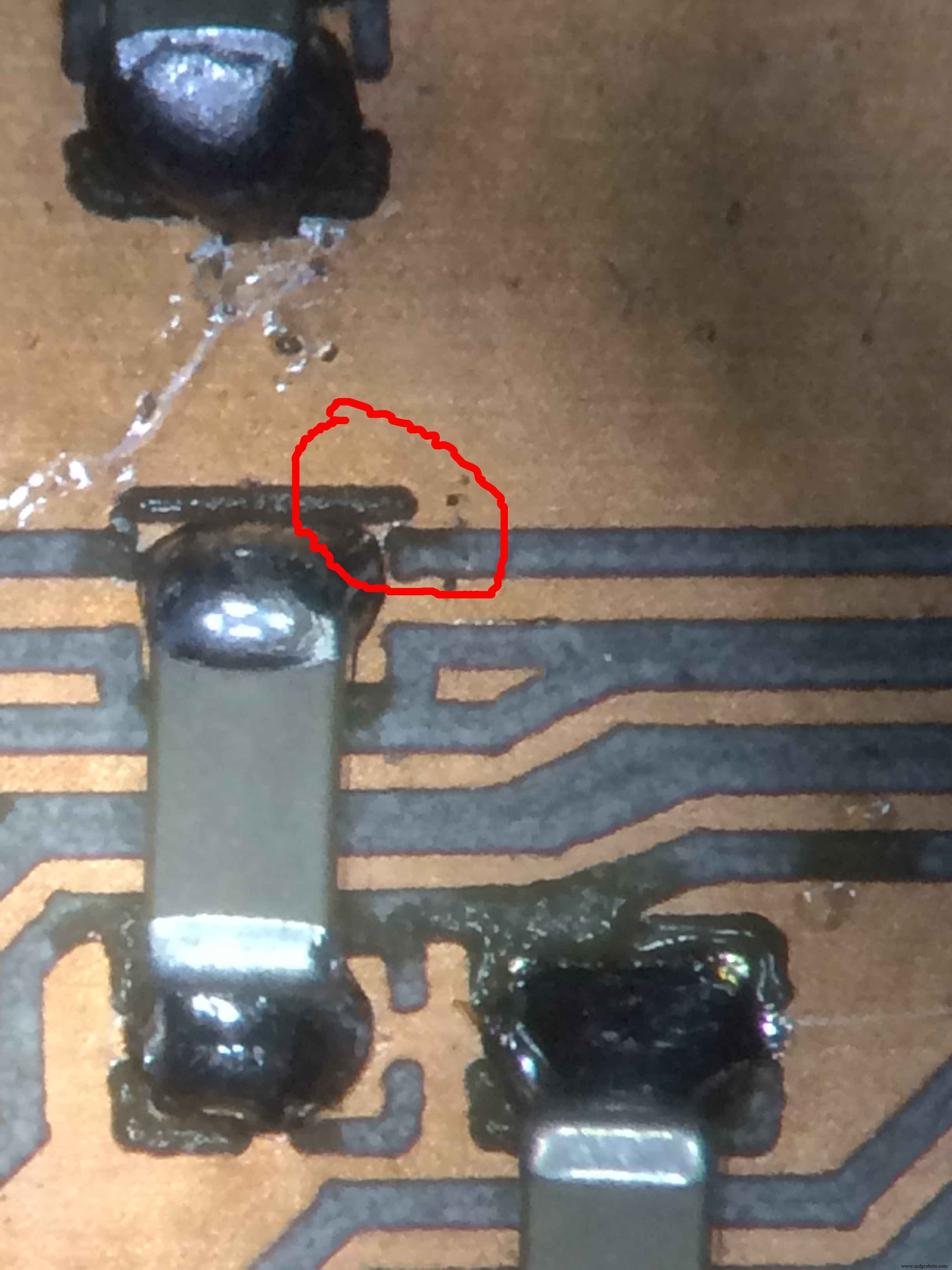
I fixed it by scratching with a knife, and increasing the isolation!
Another thing is placing the Step Up Voltage Reguator on the back side of my board.
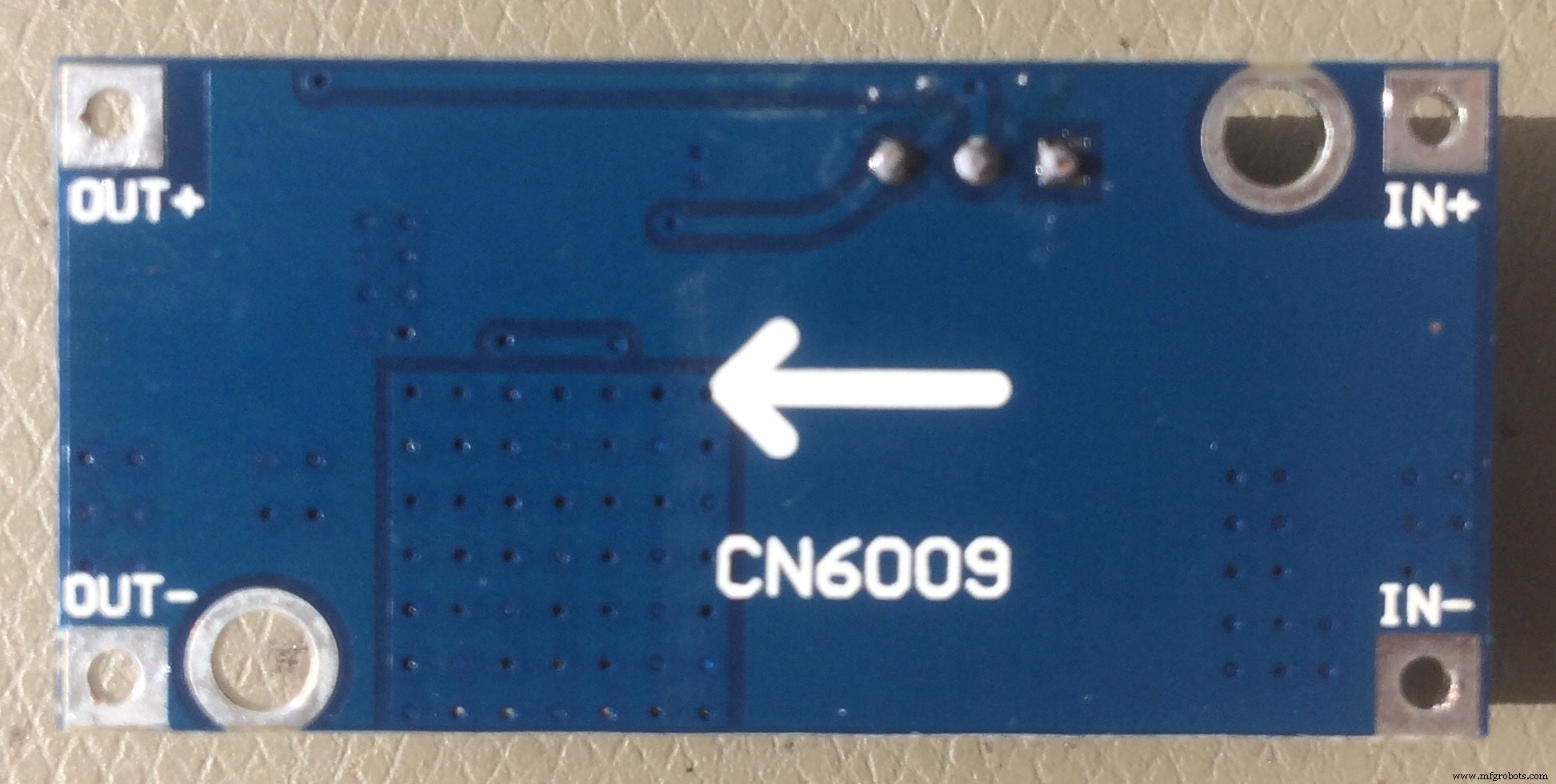
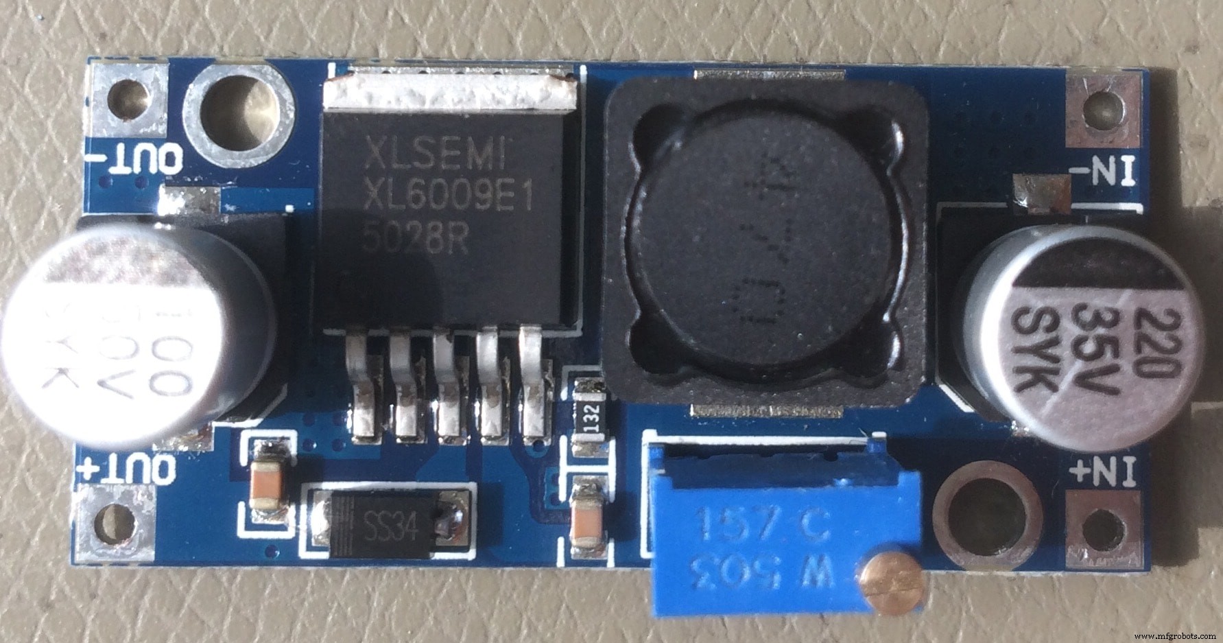
I measured the dimensions in advance, and designed predrilled holes to fix it with the pinheaders. But before soldering it on the back side, I have to calibrate it.
The idea is that when I power the board with 12V, the step up will output 24V necessary for the Ultrasonic Atomizer, which is connected to the MOSFET circuit
I used the bench power supply, with a fixed 12V, to measure the output voltage using a multimeter.
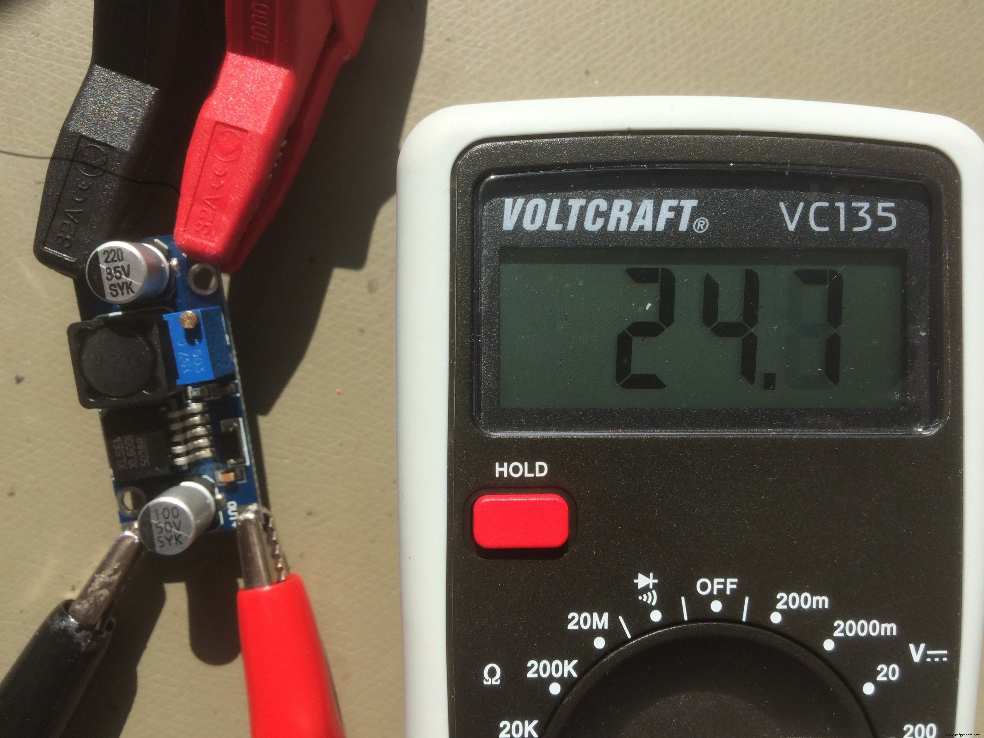
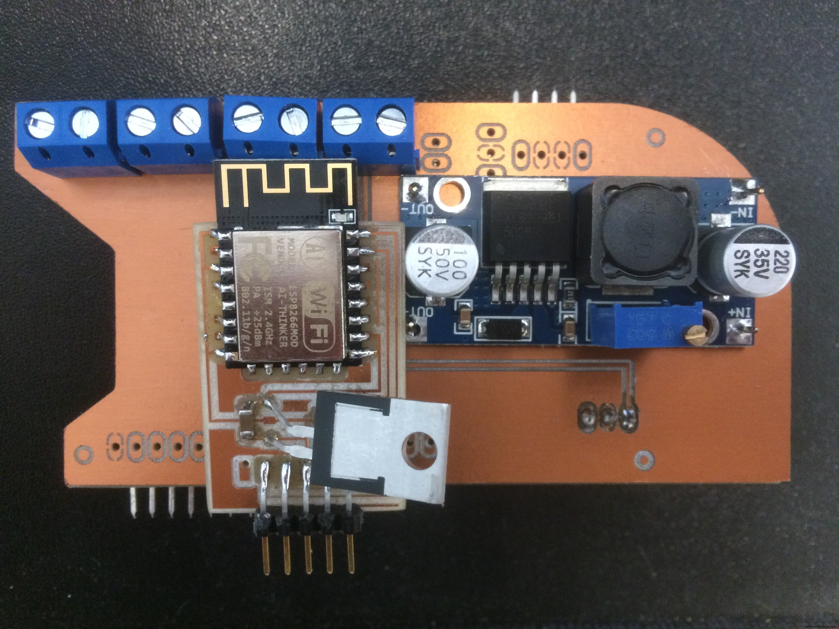
After I adjust the output to the one that I need, 24V in my case, I can solder it to the back side of my board!
Also on the back side, I placed the WiFi board which I made during the Networking and Communications week!
So, here is The BEAST :
A HERO picture for those who may think that it was easy, and everything went smooth :D
Download Files:
GIY Schematics (.sch)
GIY Layout (.brd)
Board#1 Internal Cut(.png)
Board#1 External Cut (.png)
Board#2 Internal Cut (.png)
Board#2 External Cut (.png)
Wiring &Embedded programming (I/O Devices)
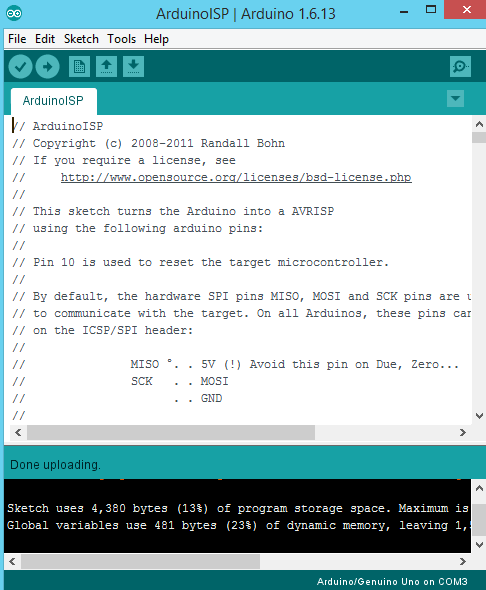
To program my board I used Arduino IDE . I connect the arduino board to the USB hub, in the tools menu select the right board (Arduino Leonardo) and the port, after go to File --> examples and open the Arduino as ISP sketch. Upload the code.
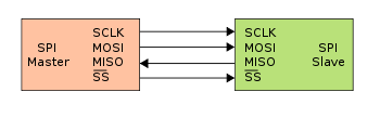
After I see done uploading, which means that the code is uploaded to the board, I disconnect the arduino from the PC. The next step is to connect my PCB board to Arduino using some wires. The connection scheme is this one:
- SCLK:Serial Clock (output from master) ----------> Arduino Pin 13
- MOSI:Master Output Slave Input ----------> Arduino Pin 11
- MISO:Master Input Slave Output ----------> Arduino Pin 12
- VCC:Positive supply voltage ----------> Arduino VCC
- GND:Ground ----------> Arduino GND
- RST:----------> Arduino Pin 10
I connect the arduino board to the USB hub. Under Tools select the right board, select Arduino as ISP programmer, double check the parameters, and press the Burn Bootloader button.
And I see Done Uploading! Good sign)
To test the board, I upload the basic Blink example code:
Ohh, I LOVE that BLINK :D Now let's go to sensors!
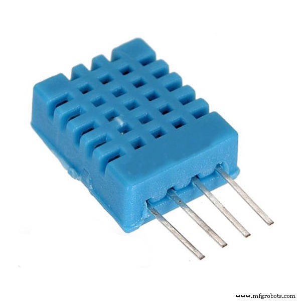
First sensor that I want to use is DHT11 - Temperature &Humidity Sensor
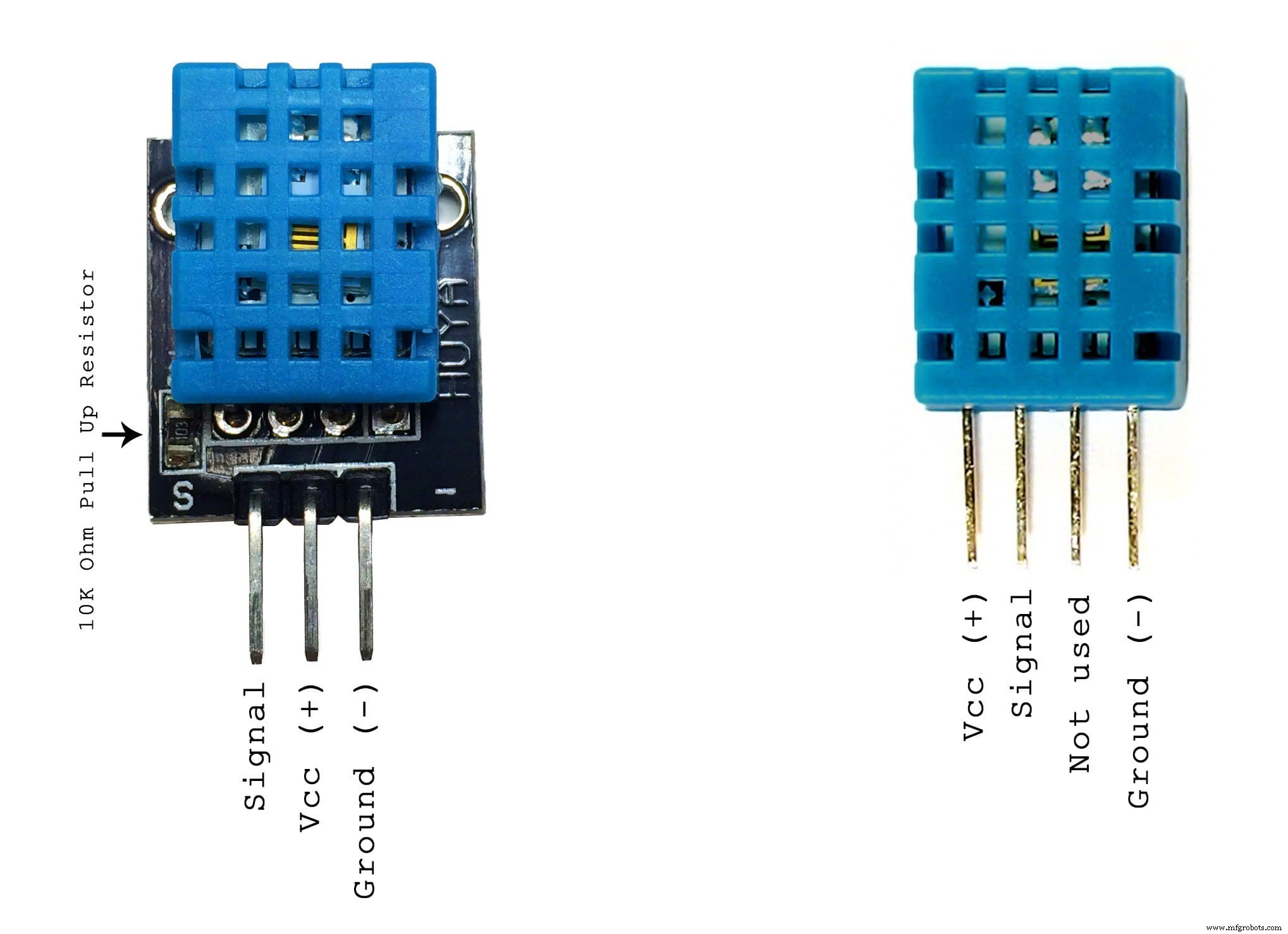
These sensors are very basic and slow, but are great for hobbyists who want to do some basic data logging. The DHT sensors are made of two parts, a capacitive humidity sensor and a thermistor. There is also a very basic chip inside that does some analog to digital conversion and spits out a digital signal with the temperature and humidity. The digital signal is fairly easy to read using any microcontroller.
Some characteristics:
- Ultra low cost
- 3 to 5V power and I/O
- 2.5mA max current use during conversion (while requesting data)
- Good for 20-80% humidity readings with 5% accuracy
- Good for 0-50°C temperature readings ±2°C accuracy
- No more than 1 Hz sampling rate (once every second)
- Body size 15.5mm x 12mm x 5.5mm
- 4 pins with 0.1" spacing
The wiring is pretty easy, just VCC, GND, and any Digital Pin! In my case, I designed in advance the connection for this sensor.
To test it, I will upload a simple sketch. The sketch includes the library DHT.h
So here is the code:
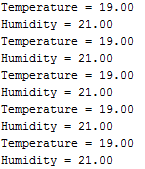
// DHT11 Temperature and Humidity Sensors Example#include "DHT.h" //include DHT library#define DHTPIN 2 //define as DHTPIN the Pin 2 used to connect the Sensor#define DHTTYPE DHT11 //define the sensor used(DHT11)DHT dht(DHTPIN, DHTTYPE); //create an instance of DHTvoid setup() { Serial.begin(9600); //initialize the Serial communication dht.begin(); //initialize the Serial communication}void loop() { float h =dht.readHumidity(); // reading Humidity float t =dht.readTemperature(); // read Temperature as Celsius (the default) Serial.print("Temperature ="); Serial.println(t, 2); //print the temperature Serial.print("Humidity =");; Serial.println(h, 2); //print the humidity delay(2000); //wait 2 seconds } When I open the Serial Monitor, this is what I get:
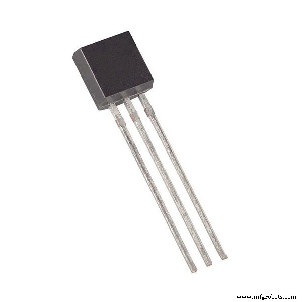
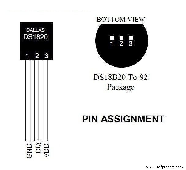
Another sensor which I want to use is DS18B20 - One Wire Digital Temperature Sensor
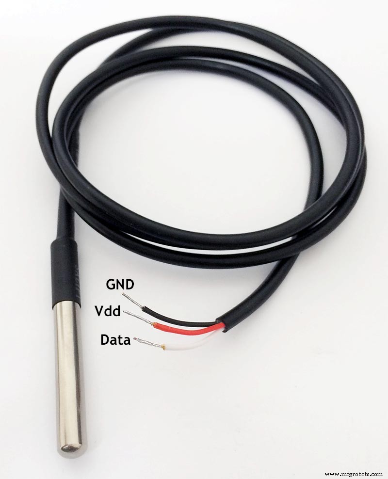
DS18B20 is 1-Wire digital temperature sensor from Maxim IC. Reports degrees in Celsius with 9 to 12-bit precision, from -55 to 125 (+/-0.5). Each sensor has a unique 64-Bit Serial number etched into it - allows for a huge number of sensors to be used on one data bus.
This is by far one of the most simple digital sensors to hookup. Aside from power and ground, it has a single digital signal pin that I will be connecting to digital pin which I designed in advance. It also requires a 4.7k pull-up resistor between the signal and power pin, which unfortunately I forgot to place on my PCB. That is why, I will solder it manually directly to the sensor cables.
Before I start, I have to download the libraries:OneWire.h and DallasTemperature.h
Upload the following sketch:
// First we include the libraries#include #include #define ONE_WIRE_BUS 3 // Setup a oneWire instance to communicate with any OneWire devices, (not just Maxim/Dallas temperature ICs) OneWire oneWire(ONE_WIRE_BUS); // Pass our oneWire reference to Dallas Temperature. DallasTemperature sensors(&oneWire);void setup(void) { // start serial port Serial.begin(9600); sensors.begin(); } void loop(void) { // call sensors.requestTemperatures() to issue a global temperature (request to all devices on the bus)sensors.requestTemperatures(); // Send the command to get temperature readings Serial.print("Temperature is:"); Serial.print(sensors.getTempCByIndex(0)); //You can have more than one DS18B20 on the same bus. 0 refers to the first IC on the wire delay(1000); } The funny thing is that after I successfully programmed the sensor, It stopped working while I was integrating all the sensors together! I spend quite a long time trying to figure out why it does not work, but due to the limited time, I decided to use another DS18B20 sensor which was available in our FabLab stock, and waterproof it by myself!
So I took the sensor, and used the datasheet to properly solder the cables, and isolate them from each other using shrink tubes
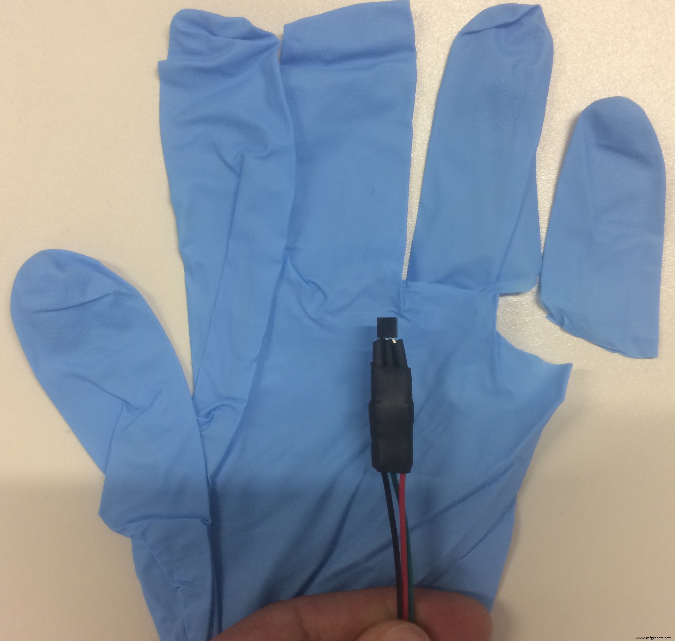
I guess you have got the idea how I am going to waterproof it, right? :D Mama ama engineer!
Said &DONE!
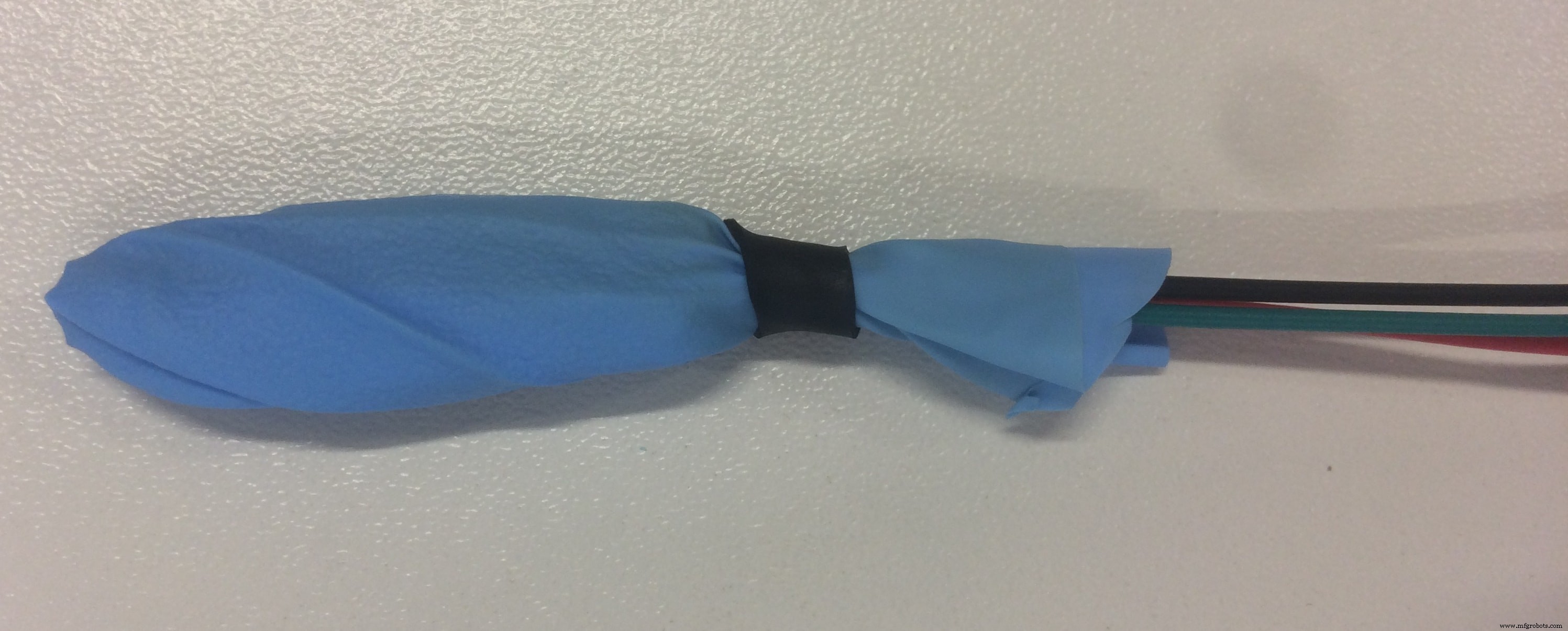
Yeah, I know what it looks like :D but I assure you, its just a hand waterproof sensor. The most important is that it works, and does not leak when submerged in water!
And we go to the next sensor which is LDR =Light Dependent Resistor
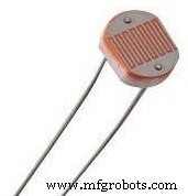
LDR is a passive electronic component, basically a resistor which has a resistance that varies depending of the light intensity. The resistance is very high in darkness, almost high as 1MΩ but when there is light that falls on the LDR, the resistance is falling down to a few KΩ (10-20kΩ @ 10 lux, 2-4kOmega; @ 100 lux) depending on the model.
The LDR gives out an analog voltage when connected to Vcc (5V), which varies in magnitude in direct proportion to the input light intensity on it. That is, the greater the intensity of light, the greater the corresponding voltage from the LDR will be. Since the LDR gives out an analog voltage, it is connected to the analog input pin on the Arduino. The Arduino, with its built-in ADC (Analog to Digital Converter), then converts the analog voltage (from 0-5V) into a digital value in the range of (0-1023). When there is sufficient light in its environment or on its surface, the converted digital values read from the LDR through the Arduino will be in the range of 800-1023.
Here is the sketch code to test the sensor:
int sensorPin =A0; /* select the input pin for LDR */int sensorValue =0; /* variable to store the value coming from the sensor */void setup(void) { Serial.begin(9600); /* start serial port */} void loop(void) { sensorValue =analogRead(sensorPin); // read the value from the sensor // We'll have a few threshholds, qualitatively determined Serial.print("LDR Value ="); Serial.print(sensorValue); if (sensorValue <100) { Serial.println(" (Dark)"); } else if (sensorValue <200) { Serial.println(" (Dim)"); } else if (sensorValue <500) { Serial.println(" (Light)"); } else if (sensorValue <800) { Serial.println(" (Bright)"); } else { Serial.println(" (Very bright)"); } delay(3000);} Next is Water Level Sensor
I want to have a water level sensor in order to receive an alarm when the water container is empty, and its time to add some water. Because I did not think about it in advance, and we did not have any water level sensor in our stock, I decided that I can make my own water sensor!
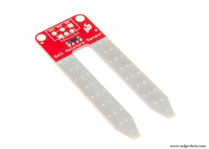
I decided to use the materials available, in my case the Soil Moisture Sensor . The basic principle of the water level sensor is to measure electric conductivity, which is the same for the soil moisture sensor. I thought that If I can calibrate the sensor in a way that will fulfil my requirements, I can use the moisture sensor like an water level sensor) In principle, this is an analog sensor and the data that we will read will be values from 0 to 1024, and the rest is just math!
But as it often happens, the reality is slightly different. When the sensor is not in touch with the water, the analog value is 0, and when I submerge only the tip, the value goes to 800. I used the following sketch to read the values:
/* Print values from analog pin A4 to serial monitor */void setup(){ Serial.begin(9600); }void loop(){ Serial.println(analogRead(A4)); delay(100);} After I can read the values, I calibrated the sensor to give out three different responses:EMPTY! - when the value is 0, LOW when the values are around 800, and Full when the values are more than 900!
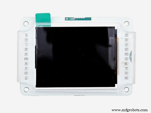
Graphic LCD Display
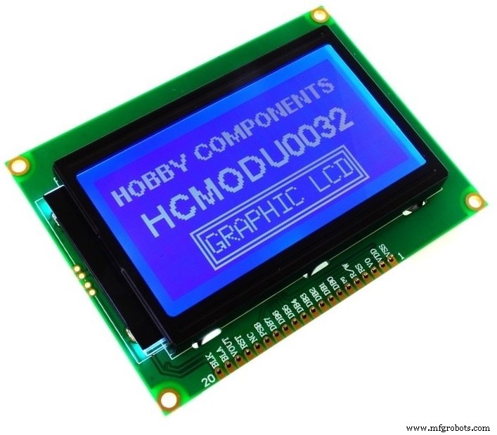
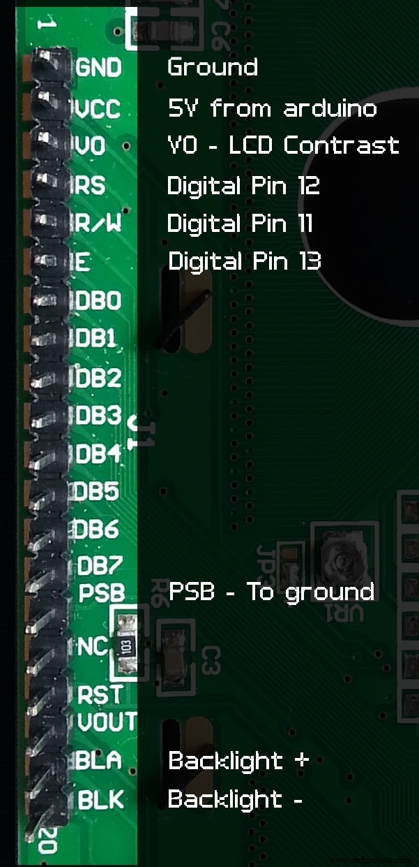
Because usually the LCD displays use a lot of pins, I had to find a way to connect the 128×64 screen in another way, and I DID!!! This way alows using only 3 Digital Pins on the board which is awesome because I may need the rest of the pins for other stuff, and it does not create a mess of wires. I premade the pins for the LCD on my PCB, and this is how I connected everything:
After I connect the LCD, It's time to programm it!
First of all, I have to download the U8glib library from HERE. Another important thing is the declared pins used in the code. The one I used are the following: U8GLIB_ST7920_128X64 u8g(4, 12, 6, U8G_PIN_NONE)
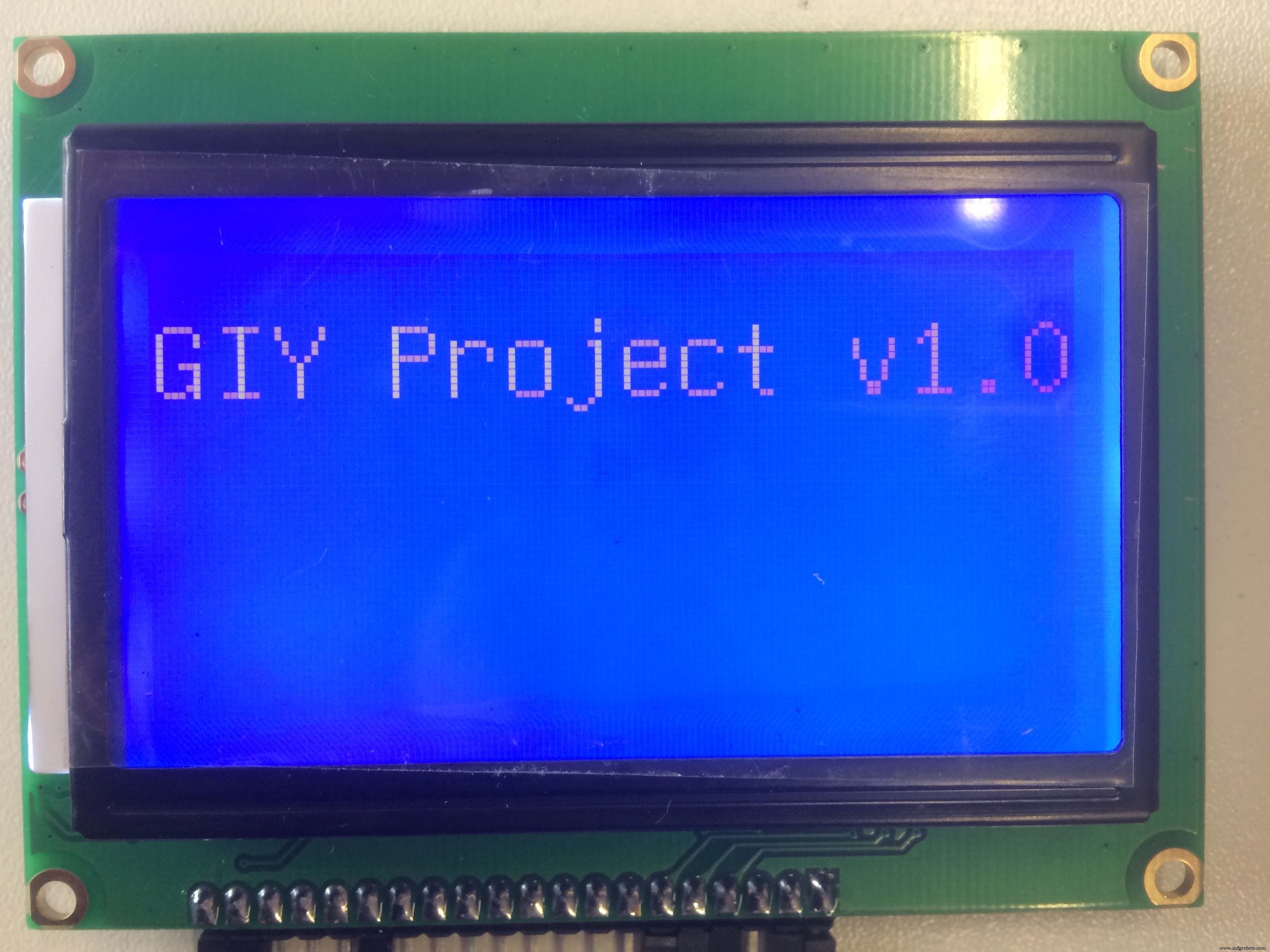
Using the "HELLO WORLD" library example, I came up with this test code:
#include "U8glib.h"U8GLIB_ST7920_128X64 u8g(4, 12, 6, U8G_PIN_NONE);void draw(void) { // graphic commands to redraw the complete screen should be placed here u8g.setFont(u8g_font_unifont); u8g.setPrintPos(0, 20); // call procedure from base class, http://arduino.cc/en/Serial/Print u8g.print("GIY Project v1.0!");}void setup(void) { // flip screen, if required // u8g.setRot180();}void loop(void) { // picture loop u8g.firstPage(); do { draw(); } while( u8g.nextPage() ); // rebuild the picture after some delay delay(500);} And this is what I get:
One cool idea that came to my mind was to display the FabLab logo for some seconds, all the time when the display is powered. I spent quite a lot of time on doing this, but I finally did it! In order to display it on the Graphic LCD, I had to have a (.bmp) format picture, and display it as a bitmap.
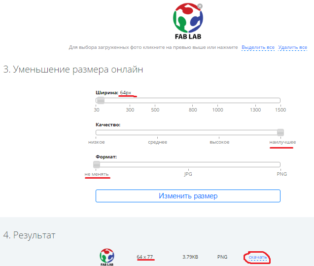
First thing which I did was download the FabLab logo from the internet as a (.png) file, and reduce it significantly in size, so it fits my small LCD borders. I used the following online service to do that:LINK
These are the configurations I used:
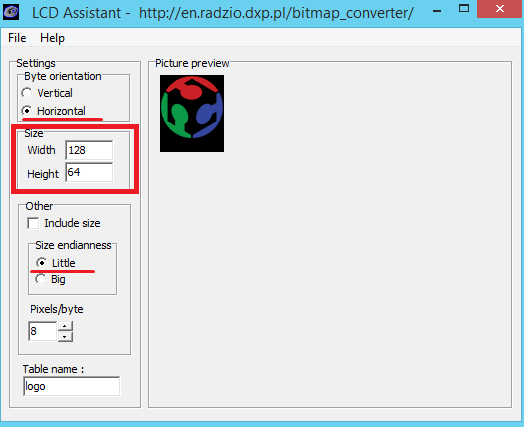
The next step is to convert my small picture into (.bmp) format. I used the following online service to do that:LINK
Now, after I have my (.bmp) file, in order to place it into my code, I have to convert it into HEX déployer. I used a nice tool called LCD Assistant . To load up an image in LCD Assistant, go to File> Load Image. A preview of the image should open up, make sure it’s the right size – 128 pixels wide, 64 pixels tall . Also make sure the Byte orientation is set to Horizontal and the Size endianness is set to Little . These are the configurations for my LCD Display:
Then I go to File> Save output to generate a temporary text file. Open that text file to have a look at my shiny new array.
pH Sensor
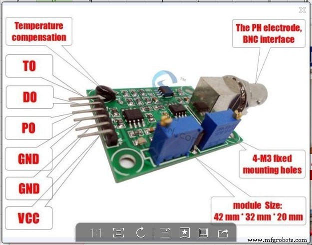
I should admit that this is the most tricky sensor from all that I played with! It is really hard to find any info about the sensor which I am using (logo ph sensor v1.1) , so I decided to make a detailed description about it!
The probe is like a (tiny) battery when placed in a liquid. Depending the pH it output a positive or negative voltage of a couple of millivolts. This value is too small and other tech stuff like impedance make it unusable directly with an Arduino, that's why you need an "op amp". The op amp board just convert the millivolts of the probe into to something acceptable for Arduino (positive between 0 and 5v).
There are 3 common buffer solutions used for pH measurement:pH 4.01, pH 6.86 and pH 9.18 (7.0 and 10.0 exists). I suggest the powder instead the liquid because it's cheaper, expire after longer and the powder can't be contaminated (vs bottle). You should read the product instructions but usually you have to put the content of the bag into 250ml of water and stir. You can use any water with an average pH (6-8) because the powder will saturate the water at the correct pH level. I personally use tap water (pH 7.4) and didn't see any difference between distilled, and demineralized water. Buffers are not stable in the time, this means that you cannot keep the solution for weeks or months.
Now let's talk more about the sensor that I am using!
- Pin To:Should be the temperature but I can't make it work
- Pin Po:Analog input signal
- Pin To:Should be the temperature but I can't make it work
- Pin Do:High/Low 3.3v adjustable limit.
- Pin G/GND:Probe ground. It is useful when the ground is not the same as your Arduino. In some circumstances the ground voltage of the liquid to measure can be different.
- Pin G/GND:Power ground (direct from the board).
- Pin V+/VCC:Input power 5V DC (direct from the board).
- Blue potentiometer (close to BNC):pH offset.
- Blue potentiometer (close to pins):limit adjustment.
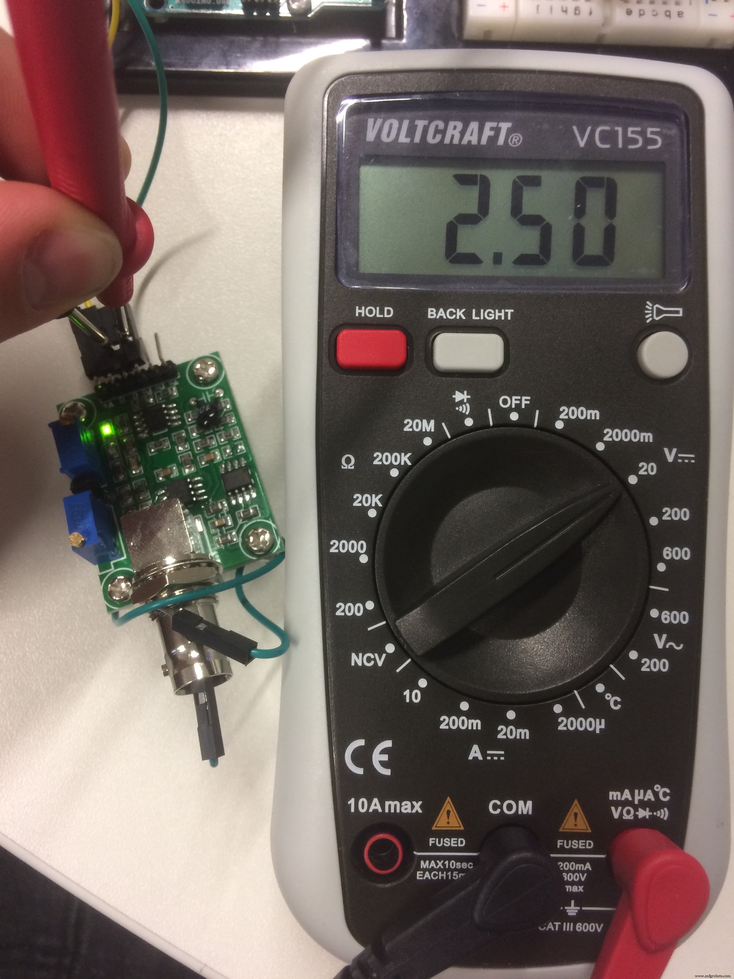
Now let's try to calibrate the sensor! There are 2 different parameters, the "offset" value and the "step" value
The offset is the shifting of all pH values to a specific voltage range. If a pH 7 output a voltage of 2.2v and pH 8 a voltage of 2.1v, then a shift of +0.3v move the pH 7 to 2.5v and the pH 8 to 2.4v. This can be done on the board or via software but it's probably easier on the board because it's probe independent and there are less programming to do.
Connect GND (both) and Vcc to Arduino GND and 5v. Remove the probe and do a short circuit between the the small BNC hole and the external part of BNC. Put a voltmeter (or Arduino) to measure the voltage between GND and Po. Adjust the pot (close BNC) until the output is 2.5v. Now the pH 7 have an exact value of 2.5v (511 with analogRead function) because the probe will output 0 millivolt.
To calibrate the steps I need one or more buffer solutions depending on the range and precision required. Ideally it is better to know the range of the measure with the system. I use water between pH 5 and pH 7, then I choose the buffer 4.01 (and 6.86 to verify my stuff). If you usually measure pH between 8 and 10 choose buffer 9.18 (eventually 6.86 also).
I connect the (clean) probe and put it in the buffer, then let it stabilize for a minute. I know it's stable when it goes up and down (3.04 then 3.05 then 3.03 then 3.04).Take note of the voltmeter (or Arduino) value, in my example it's 3.05v.
That's all, now I can use it with the code below.
int ph_pin =A7; //This is the pin number connected to Povoid setup() { Serial.begin(9600);}void loop() { int measure =analogRead(ph_pin); Serial.print("Measure:"); Serial.print(measure); double voltage =5 / 1024.0 * measure; //classic digital to voltage conversion Serial.print("\tVoltage:"); Serial.print(voltage, 3); // PH_step =(voltage@PH7 - voltage@PH4) / (PH7 - PH4) // PH_probe =PH7 - ((voltage@PH7 - voltage@probe) / PH_step) float Po =7 + ((2.5 - voltage) / 0.18); Serial.print("\tPH:"); Serial.print(Po, 3); Serial.println(""); delay(2000);} The PH_step calculation is quite simple. I take the difference between the two known voltage, in my example 2.5v@pH7 and 3.05v@pH4.01 which is -0.55v. It's the voltage range equivalent of the pH range from 7 to 4.01, which is 2.99 pH units. A small division of the voltage by pH units gives a volts per pH number (0, 1839... in my case).
The PH_probe is calculated by taking the known pH 7 voltage (2.5v) where we add some PH_step to match the probe voltage. This means that a pH of 8 has a voltage value of 2.5v (pH 7) + 0.1839 (1 unit/step); pH 9 then is 2.5v + 0.1839 + 0.1839 =2.87v.
No magic, JUST MATH :D
MOSFET output:
I connected the RGB LED stripe and the Ultrasonic Atomizer to the MOSFET circuit outputs, which are controlled by digital pins. For the LED lights, I stated in the setup digitalWrite (LED, HIGH); , which means that the LED will switch on all the time when the system is powered. For the Fog maker, I made an If function depending on the water level value. If there is water, the fog maker is ON, if there is no water, EMPTY!, then the fog is OFF!
Now Let's put things together!
Here I came up with my final code:
#include "dht.h"#include "U8glib.h"#include #include #define DHT11_PIN 2 // what digital pin we're connected to#define ONE_WIRE_BUS 3#define WATER_LEVEL A4#define LDR_PIN A3#define PH_PIN A5#define GROW_LIGHT 10#define FOG_PUMP 13int waterLevel;int LightLevel;int pH;dht DHT;OneWire oneWire(ONE_WIRE_BUS); DallasTemperature waterTemp(&oneWire);U8GLIB_ST7920_128X64 u8g(4, 12, 6, U8G_PIN_NONE);const unsigned char logo [] PROGMEM ={0xFF, 0xFF, 0xFF, 0xFE, 0x7F, 0xFF, 0xFF, 0xFF, 0x00, 0x00, 0x00, 0x00, 0x00, 0x00, 0x00, 0x00,0xFF, 0xFF, 0xFF, 0x00, 0x00, 0xFF, 0xFF, 0xFF, 0x00, 0x00, 0x00, 0x00, 0x00, 0x00, 0x00, 0x00,0xFF, 0xFF, 0xF8, 0x00, 0x00, 0x1F, 0xFF, 0xFF, 0x00, 0x00, 0x00, 0x00, 0x00, 0x00, 0x00, 0x00,0xFF, 0xFF, 0xC0, 0x00, 0x00, 0x03, 0xFF, 0xFF, 0x00, 0x00, 0x00, 0x00, 0x00, 0x00, 0x00, 0x00,0xFF, 0xFF, 0x00, 0x00, 0x00, 0x00, 0xFF, 0xFF, 0x00, 0x00, 0x00, 0x00, 0x00, 0x00, 0x00, 0x00,0xFF, 0xFE, 0x00, 0x03, 0xC0, 0x00, 0x7F, 0xFF, 0x00, 0x00, 0x00, 0x00, 0x00, 0x00, 0x00, 0x00,0xFF, 0xF8, 0x00, 0x07, 0xE0, 0x00, 0x3F, 0xFF, 0x00, 0x00, 0x00, 0x00, 0x00, 0x00, 0x00, 0x00,0xFF, 0xF0, 0x00, 0x1F, 0xF8, 0x00, 0x0F, 0xFF, 0x00, 0x00, 0x00, 0x00, 0x00, 0x00, 0x00, 0x00,0xFF, 0xE0, 0x00, 0x3F, 0xFE, 0x00, 0x07, 0xFF, 0x00, 0x00, 0x00, 0x00, 0x00, 0x00, 0x00, 0x00,0xFF, 0xC0, 0x00, 0x18, 0x1F, 0x00, 0x03, 0xFF, 0x00, 0x00, 0x00, 0x00, 0x00, 0x00, 0x00, 0x00,0xFF, 0x80, 0x00, 0x00, 0x03, 0xC0, 0x01, 0xFF, 0x00, 0x00, 0x00, 0x00, 0x00, 0x00, 0x00, 0x00,0xFF, 0x00, 0x00, 0x00, 0x00, 0xF0, 0x00, 0xFF, 0x00, 0x00, 0x00, 0x00, 0x00, 0x00, 0x00, 0x00,0xFE, 0x00, 0x00, 0x00, 0x00, 0x7C, 0x00, 0x7F, 0x00, 0x00, 0x00, 0x00, 0x00, 0x00, 0x00, 0x00,0xFC, 0x00, 0x00, 0x00, 0x00, 0x3E, 0x00, 0x7F, 0x00, 0x00, 0x00, 0x00, 0x00, 0x00, 0x00, 0x00,0xFC, 0x03, 0x80, 0x00, 0x00, 0x3F, 0x80, 0x3F, 0x00, 0x00, 0x00, 0x00, 0x00, 0x00, 0x00, 0x00,0xF8, 0x07, 0xE0, 0x00, 0x00, 0x1F, 0xE0, 0x1F, 0x00, 0x00, 0x00, 0x00, 0x00, 0x00, 0x00, 0x00,0xFC, 0x1F, 0xF0, 0x00, 0x00, 0x1F, 0xF0, 0x1F, 0x00, 0x00, 0x00, 0x00, 0x00, 0x00, 0x00, 0x00,0xF0, 0x3F, 0xF0, 0x00, 0x00, 0x1F, 0xFC, 0x0F, 0x00, 0x00, 0x00, 0x00, 0x00, 0x00, 0x00, 0x00,0xF0, 0xFF, 0xF0, 0x00, 0x00, 0x1F, 0xFF, 0x0F, 0x00, 0x00, 0x00, 0x00, 0x00, 0x00, 0x00, 0x00,0xE0, 0xFF, 0xF0, 0x00, 0x00, 0x3F, 0xFF, 0x07, 0x00, 0x00, 0x00, 0x00, 0x00, 0x00, 0x00, 0x00,0xE0, 0xFF, 0xF0, 0x00, 0x00, 0x3F, 0xFF, 0x07, 0x00, 0x00, 0x00, 0x00, 0x00, 0x00, 0x00, 0x00,0xC0, 0xFF, 0xF8, 0x00, 0x00, 0x7F, 0xFF, 0x03, 0x00, 0x00, 0x00, 0x00, 0x00, 0x00, 0x00, 0x00,0xC0, 0xFF, 0xFC, 0x00, 0x00, 0xFF, 0xFF, 0x03, 0x00, 0x00, 0x00, 0x00, 0x00, 0x00, 0x00, 0x00,0xC0, 0xFF, 0xFF, 0x00, 0x01, 0xFF, 0xFF, 0x03, 0x00, 0x00, 0x00, 0x00, 0x00, 0x00, 0x00, 0x00,0x80, 0xFF, 0xFF, 0xC0, 0x07, 0xFF, 0xFF, 0x01, 0x00, 0x00, 0x00, 0x00, 0x00, 0x00, 0x00, 0x00,0x80, 0xFF, 0xFF, 0xFF, 0xFF, 0xFF, 0xFF, 0x01, 0x00, 0x00, 0x00, 0x00, 0x00, 0x00, 0x00, 0x00,0x80, 0xFF, 0xFF, 0xFF, 0xFF, 0xFF, 0xFF, 0x01, 0x00, 0x00, 0x00, 0x00, 0x00, 0x00, 0x00, 0x00,0x80, 0xFF, 0xFF, 0xFF, 0xFF, 0xFF, 0xFF, 0x01, 0x00, 0x00, 0x00, 0x00, 0x00, 0x00, 0x00, 0x00,0x80, 0xFE, 0x1F, 0xFF, 0xFF, 0xF0, 0x3C, 0x01, 0x00, 0x00, 0x00, 0x00, 0x00, 0x00, 0x00, 0x00,0x80, 0xF8, 0x03, 0xFF, 0xFF, 0xC0, 0x10, 0x01, 0x00, 0x00, 0x00, 0x00, 0x00, 0x00, 0x00, 0x00,0x80, 0xF0, 0x01, 0xFF, 0xFF, 0x80, 0x00, 0x01, 0x00, 0x00, 0x00, 0x00, 0x00, 0x00, 0x00, 0x00,0x00, 0xF0, 0x00, 0xFF, 0xFF, 0x00, 0x00, 0x01, 0x00, 0x00, 0x00, 0x00, 0x00, 0x00, 0x00, 0x00,0x00, 0xE0, 0x00, 0x7F, 0xFE, 0x00, 0x00, 0x01, 0x00, 0x00, 0x00, 0x00, 0x00, 0x00, 0x00, 0x00,0x80, 0xE0, 0x00, 0x3F, 0xFC, 0x00, 0x00, 0x01, 0x00, 0x00, 0x00, 0x00, 0x00, 0x00, 0x00, 0x00,0x80, 0xE0, 0x00, 0x1F, 0xFC, 0x00, 0x00, 0x01, 0x00, 0x00, 0x00, 0x00, 0x00, 0x00, 0x00, 0x00,0x80, 0xE0, 0x00, 0x1F, 0xF8, 0x00, 0x00, 0x01, 0x00, 0x00, 0x00, 0x00, 0x00, 0x00, 0x00, 0x00,0x80, 0xE0, 0x00, 0x0F, 0xF8, 0x00, 0x00, 0x01, 0x00, 0x00, 0x00, 0x00, 0x00, 0x00, 0x00, 0x00,0x80, 0xE0, 0x00, 0x0F, 0xF0, 0x00, 0x00, 0x01, 0x00, 0x00, 0x00, 0x00, 0x00, 0x00, 0x00, 0x00,0x80, 0xE0, 0x00, 0x0F, 0xF0, 0x00, 0x01, 0x01, 0x00, 0x00, 0x00, 0x00, 0x00, 0x00, 0x00, 0x00,0x80, 0xE0, 0x00, 0x07, 0xF0, 0x00, 0x07, 0x01, 0x00, 0x00, 0x00, 0x00, 0x00, 0x00, 0x00, 0x00,0xC0, 0xF0, 0x00, 0x07, 0xF0, 0x00, 0x07, 0x03, 0x00, 0x00, 0x00, 0x00, 0x00, 0x00, 0x00, 0x00,0xC0, 0xF0, 0x00, 0x07, 0xF0, 0x00, 0x0F, 0x03, 0x00, 0x00, 0x00, 0x00, 0x00, 0x00, 0x00, 0x00,0xC0, 0xF8, 0x00, 0x07, 0xF0, 0x00, 0x0F, 0x03, 0x00, 0x00, 0x00, 0x00, 0x00, 0x00, 0x00, 0x00,0xC0, 0xF8, 0x00, 0x07, 0xF0, 0x00, 0x1F, 0x07, 0x00, 0x00, 0x00, 0x00, 0x00, 0x00, 0x00, 0x00,0xE0, 0xFC, 0x00, 0x07, 0xF0, 0x00, 0x1F, 0x07, 0x00, 0x00, 0x00, 0x00, 0x00, 0x00, 0x00, 0x00,0xE0, 0xFE, 0x00, 0x0F, 0xF0, 0x00, 0x3F, 0x07, 0x00, 0x00, 0x00, 0x00, 0x00, 0x00, 0x00, 0x00,0xF0, 0x3E, 0x00, 0x0F, 0xF0, 0x00, 0x7C, 0x0F, 0x00, 0x00, 0x00, 0x00, 0x00, 0x00, 0x00, 0x00,0xF0, 0x1E, 0x00, 0x1F, 0xF8, 0x00, 0xF8, 0x0F, 0x00, 0x00, 0x00, 0x00, 0x00, 0x00, 0x00, 0x00,0xF8, 0x06, 0x00, 0x1F, 0xFC, 0x01, 0xE0, 0x1F, 0x00, 0x00, 0x00, 0x00, 0x00, 0x00, 0x00, 0x00,0xFC, 0x00, 0x00, 0x7F, 0xFF, 0x0F, 0x80, 0x3F, 0x00, 0x00, 0x00, 0x00, 0x00, 0x00, 0x00, 0x00,0xFC, 0x00, 0x00, 0x7F, 0xFF, 0xFF, 0x00, 0x3F, 0x00, 0x00, 0x00, 0x00, 0x00, 0x00, 0x00, 0x00,0xFE, 0x00, 0x00, 0x7F, 0xFF, 0xFC, 0x00, 0x7F, 0x00, 0x00, 0x00, 0x00, 0x00, 0x00, 0x00, 0x00,0xFF, 0x00, 0x00, 0x7F, 0xFF, 0xF0, 0x00, 0xFF, 0x00, 0x00, 0x00, 0x00, 0x00, 0x00, 0x00, 0x00,0xFF, 0x80, 0x00, 0x7F, 0xFF, 0xC0, 0x01, 0xFF, 0x00, 0x00, 0x00, 0x00, 0x00, 0x00, 0x00, 0x00,0xFF, 0xC0, 0x00, 0x7F, 0xFF, 0x80, 0x03, 0xFF, 0x00, 0x00, 0x00, 0x00, 0x00, 0x00, 0x00, 0x00,0xFF, 0xE0, 0x00, 0x7F, 0xFE, 0x00, 0x07, 0xFF, 0x00, 0x00, 0x00, 0x00, 0x00, 0x00, 0x00, 0x00,0xFF, 0xF0, 0x00, 0x1F, 0xF8, 0x00, 0x0F, 0xFF, 0x00, 0x00, 0x00, 0x00, 0x00, 0x00, 0x00, 0x00,0xFF, 0xF8, 0x00, 0x0F, 0xF0, 0x00, 0x1F, 0xFF, 0x00, 0x00, 0x00, 0x00, 0x00, 0x00, 0x00, 0x00,0xFF, 0xFC, 0x00, 0x03, 0xC0, 0x00, 0x3F, 0xFF, 0x00, 0x00, 0x00, 0x00, 0x00, 0x00, 0x00, 0x00,0xFF, 0xFF, 0x00, 0x00, 0x00, 0x00, 0xFF, 0xFF, 0x00, 0x00, 0x00, 0x00, 0x00, 0x00, 0x00, 0x00,0xFF, 0xFF, 0xC0, 0x00, 0x00, 0x03, 0xFF, 0xFF, 0x00, 0x00, 0x00, 0x00, 0x00, 0x00, 0x00, 0x00,0xFF, 0xFF, 0xF0, 0x00, 0x00, 0x1F, 0xFF, 0xFF, 0x00, 0x00, 0x00, 0x00, 0x00, 0x00, 0x00, 0x00,0xFF, 0xFF, 0xFE, 0x00, 0x00, 0x7F, 0xFF, 0xFF, 0x00, 0x00, 0x00, 0x00, 0x00, 0x00, 0x00, 0x00,0xFF, 0xFF, 0xFF, 0xFD, 0x3F, 0xFF, 0xFF, 0xFF, 0x00, 0x00, 0x00, 0x00, 0x00, 0x00, 0x00, 0x00};bool first;float hum =0.0;double T=0.0;void dht_test(float * humPerc);void setup(void) { waterTemp.begin(); pinMode (GROW_LIGHT, OUTPUT); pinMode (FOG_PUMP, OUTPUT); digitalWrite (GROW_LIGHT, HIGH); first =true; // assign default color value if ( u8g.getMode() ==U8G_MODE_R3G3B2 ) { u8g.setColorIndex(255); // white } else if ( u8g.getMode() ==U8G_MODE_GRAY2BIT ) { u8g.setColorIndex(3); // max intensity } else if ( u8g.getMode() ==U8G_MODE_BW ) { u8g.setColorIndex(1); // pixel on } else if ( u8g.getMode() ==U8G_MODE_HICOLOR ) { u8g.setHiColorByRGB(255,255,255); } // picture loop u8g.firstPage(); do { u8g.drawBitmapP( 32, 0, 16, 64, logo); } while( u8g.nextPage() ); dht_test(&hum);}void RefreshDisplay(float * humPerc, double *T, int *WL, int *LL, int *pH_value) { u8g.setFont(u8g_font_fub11); u8g.setFontRefHeightExtendedText(); u8g.setDefaultForegroundColor(); u8g.setFontPosTop(); u8g.drawStr( 4, 0, "Hum%"); u8g.setPrintPos( 68, 0); u8g.print( *humPerc); u8g.drawStr( 4, 15, "Temp"); u8g.setPrintPos( 68, 15); u8g.print( *T); u8g.drawStr( 4, 30, "Wlvl"); if (*WL ==0){ u8g.drawStr (68, 30,"EMPTY!"); digitalWrite (FOG_PUMP, LOW); } else{ if (*WL <800) u8g.drawStr (68, 30,"LOW"); else { digitalWrite(FOG_PUMP, HIGH); u8g.drawStr (68, 30,"HIGH"); } } if (*LL <100) { u8g.drawStr (68, 45,"Dark"); } else if (*LL <200) { u8g.drawStr (68, 45,"Dim"); } else if (*LL <500) { u8g.drawStr (68, 45, "Light"); } else if (*LL <800) { u8g.drawStr (68, 45,"Bright"); } else { u8g.drawStr (68, 45,"2Bright"); } double voltage =5.0 / 1024.0 * (*pH_value); float Po =7 + ((2.5 - voltage) / 0.18); u8g.drawStr (4, 45,"pH"); u8g.setPrintPos( 28, 45); u8g.print( Po); }void loop(void) {waterTemp.requestTemperatures();T =waterTemp.getTempCByIndex(0);waterLevel =analogRead(WATER_LEVEL);LightLevel =analogRead(LDR_PIN);pH =analogRead (PH_PIN);char status;int chk =DHT.read11(DHT11_PIN);hum =DHT.humidity; dht_test(&hum); if(first) { first =false; } else { u8g.firstPage(); do { RefreshDisplay(&hum, &T,&waterLevel, &LightLevel, &pH); } while( u8g.nextPage() ); }}void dht_test(float * humPerc) { // Wait a few seconds between measurements. delay(1000);}
Download Files:
GIY Final Code (.ino)
3D Design &3D Printing
Actually for my final system, I used a lot of 3D design and 3D printing technique. I used two different printers, and played a lot with the settings until I got the desired result!
For 3D design, I used which as I mentioned before, is my favourite CAD software! I will not go too much into details of how to create simple shapes, and extrude objects, all this could be found during my Computer-Aided Design week, where I learned how to use diferent softwares, as well as 3D Scanning and Printing week.

The main task was to design the physical appearence of my system! The challenge was that I wanted it to look SEXY!!!
The aesthetics was a very important criteria, as well as functionality! The system should also be assemblable, which makes it even more challenging. I also wanted to integrate the skills which I learned like 3D printing, CNC milling, Laser cutting etc.
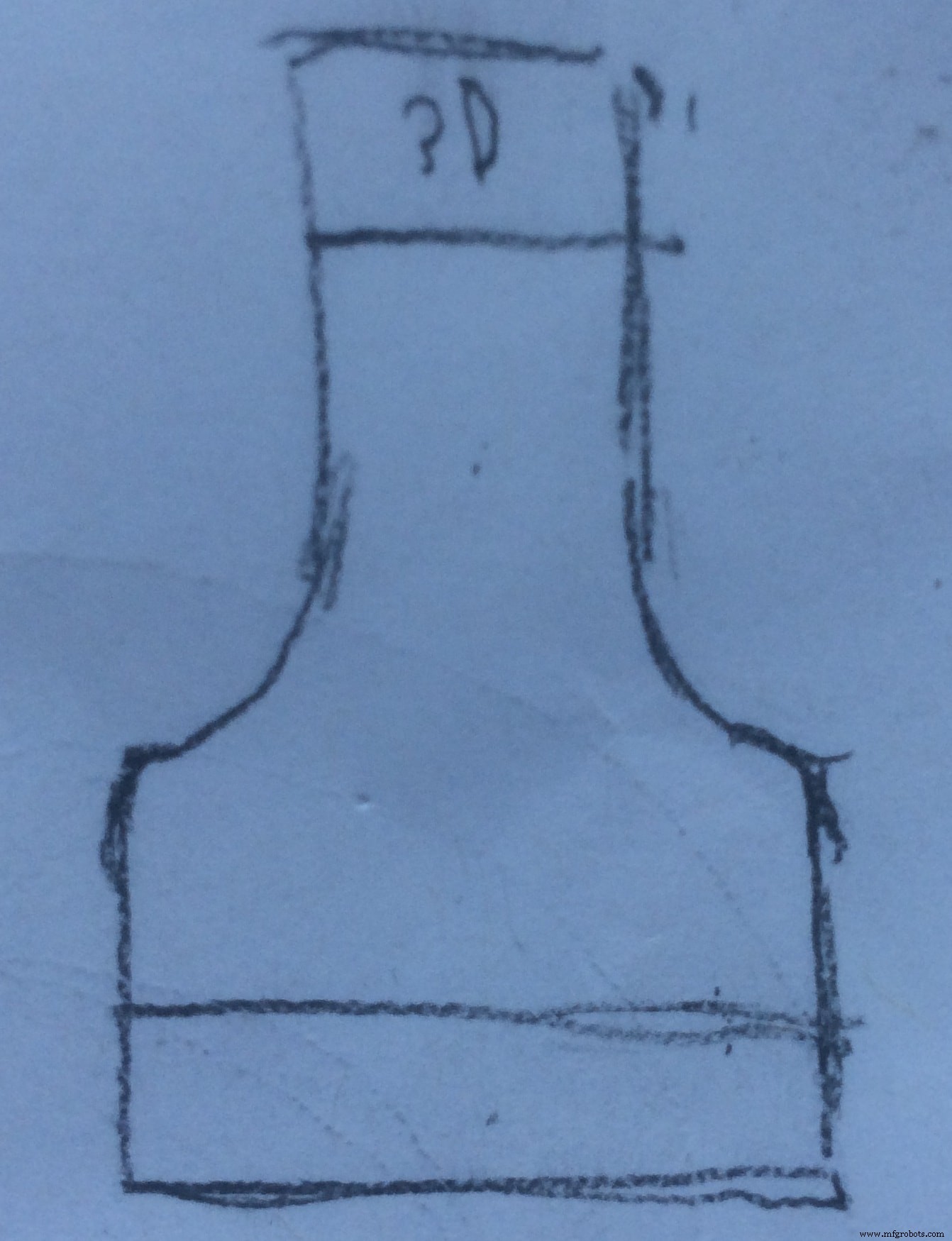
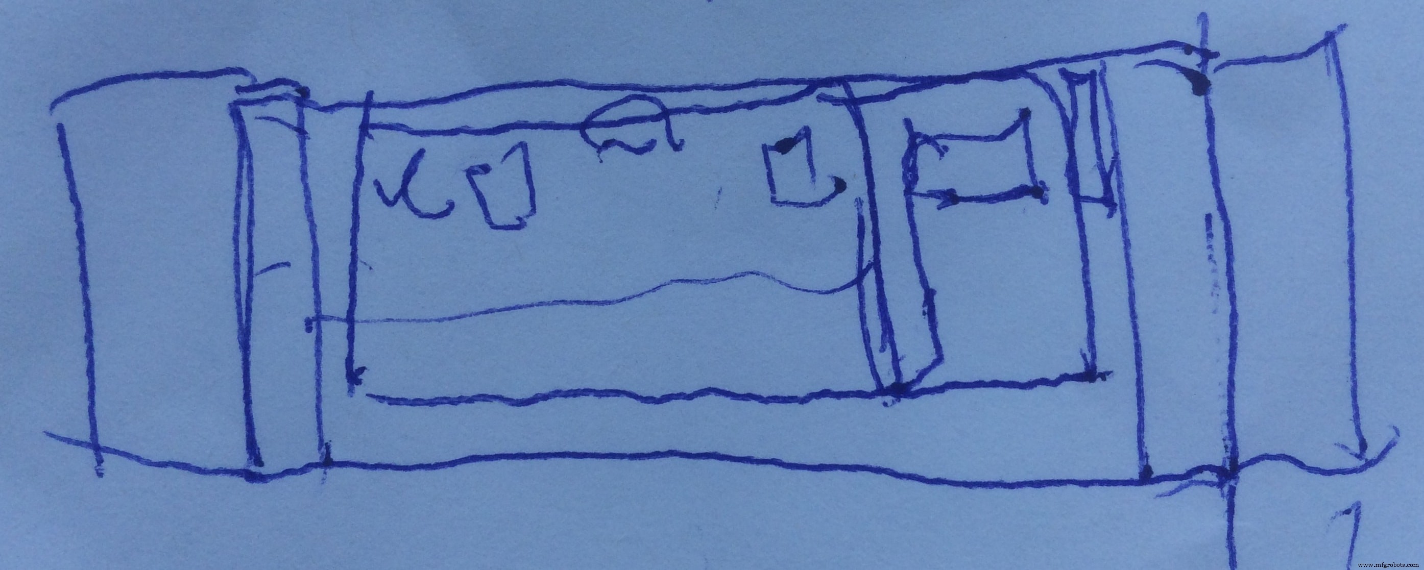
Before designing it in the digital world, I made a simple sketch on paper! Here it is:
And this is the final 3D design:
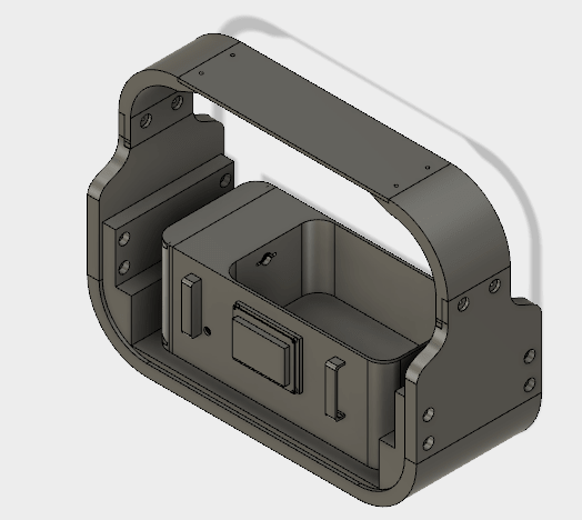
My sexy ass system :D
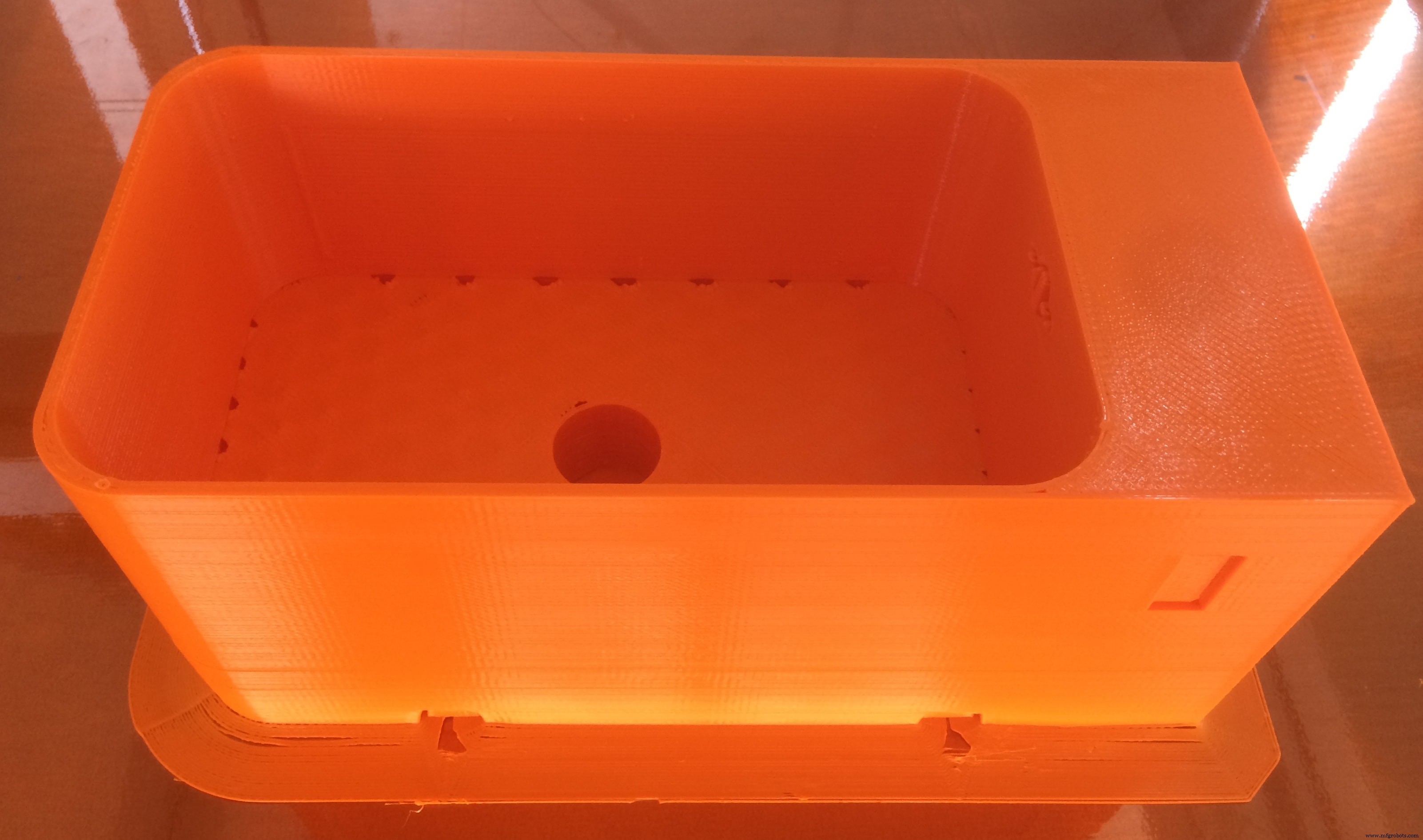
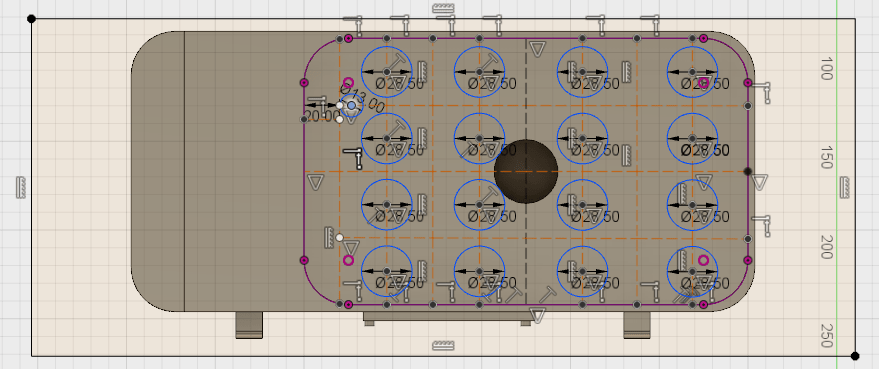
First thing which I designed was the water container . Here it is:
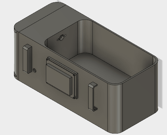
It incorporates several features! First, there is enough space for plants to grow, as well as in the middle I made a hole to place the Ultrasonic Atomizer. It is done because I wanted to level the fogger with the container. The thing is that the water level should be above the fogger by 2cm, so all the water which is leveled with the fogger hight, will not be used (waste)! So if I place the fogger below the container level, I have a water zero level exactly at the point where it should be, zero for the container =2cm above the fogger. In this way, all the water is used!
I also considered the hight of the container. Actually, all the dimensions of the container are measured during the experimental stage!
As you can see, I made a hole on the wall, which will be used for the cables from sensors placed in the water to hide into the electronics section. In the front of the container, I made the slot to attach the graphic display. I also designed some handles to easily remove the container when need!
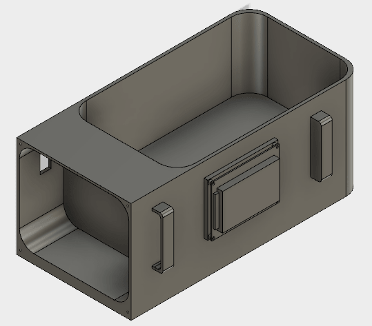
From this perspective, you can see the electronics section. Now its opened, but I also designed a lid to close it. Inside the electronics section, I designed a hole to have access to power and program the board
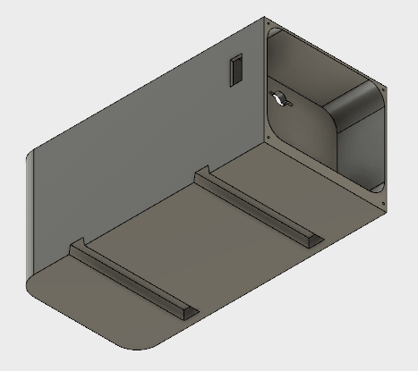
On the bottom side I designed sliders which will be attached to the rest of the system, and make it easier to remove the container when needed, it will also play a role of fixation of the container in place!
And now Let's Print It!
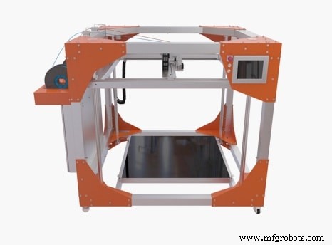
I can proudly announce that the printer which I will be using is called BigRep 3D Printer , only available in our FabLab Kamp-Lintfort. It has a capacity of one cubic meter, and provides the largest FFF build volume for professional and industrial use.
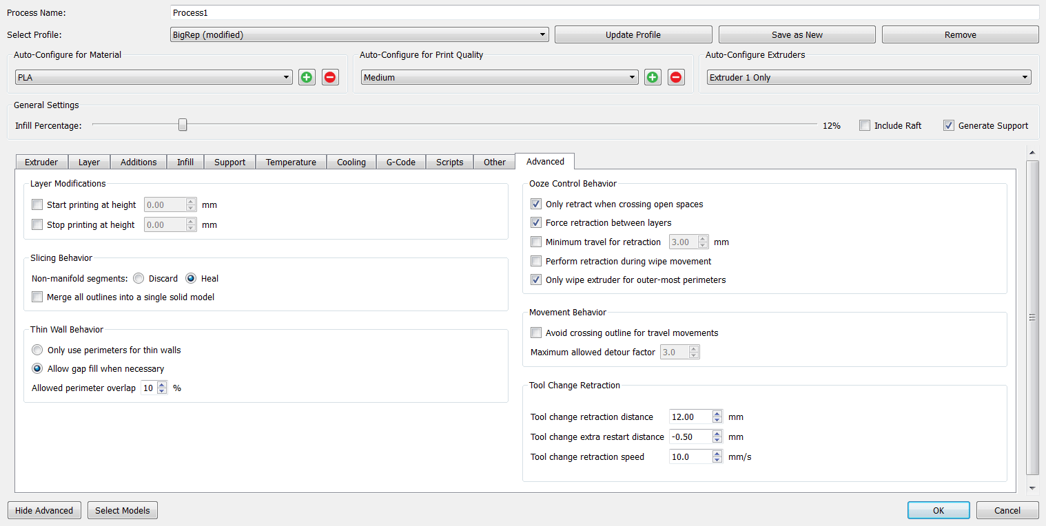
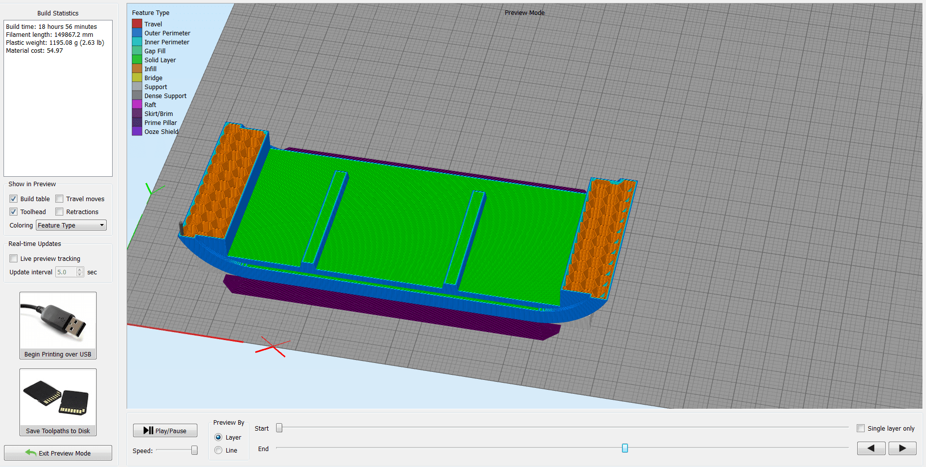
The slicing software which I use is Simplify3D , one of the most advanced slicing tools, in my opinion, with a lot of configurations and options.

I do not think that there is a right and a wrong way to print something, you just have to play with the settings until you find the best options for the specific object to print.
Because this printer is new, there are not too many testings made. So, I had to experiment with the settings, and try, try and again try...
I will show bellow the settings that I will be using for my water container print, but some of them are intuitive.
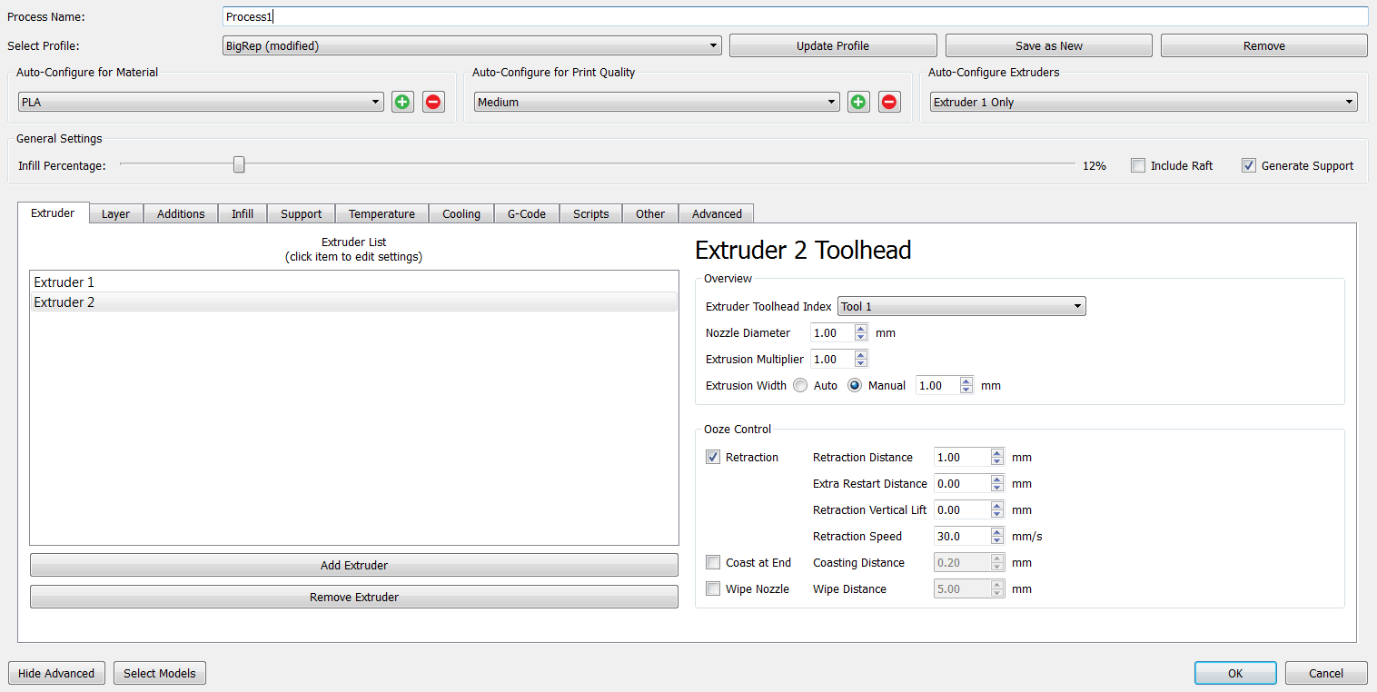
I choose the Tool1 , because the BigRep Printer has two nozzels with two different filaments, and I have to specify which nozzel I want to use, as well as the nozzle diameter and the rest of the settings.
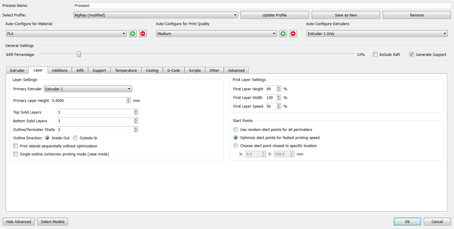
Layer:
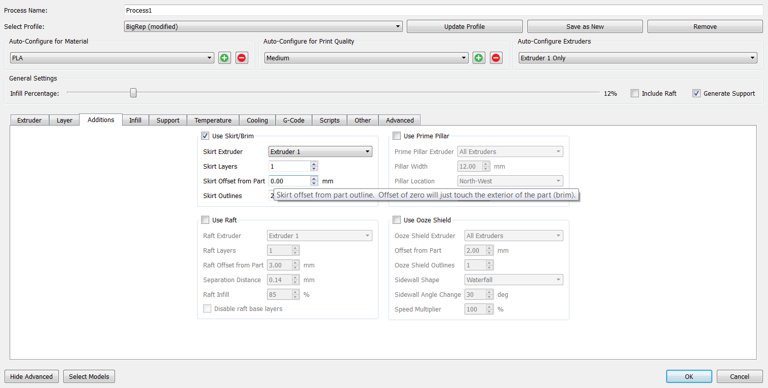
Additions:
Infill:
Assistance :
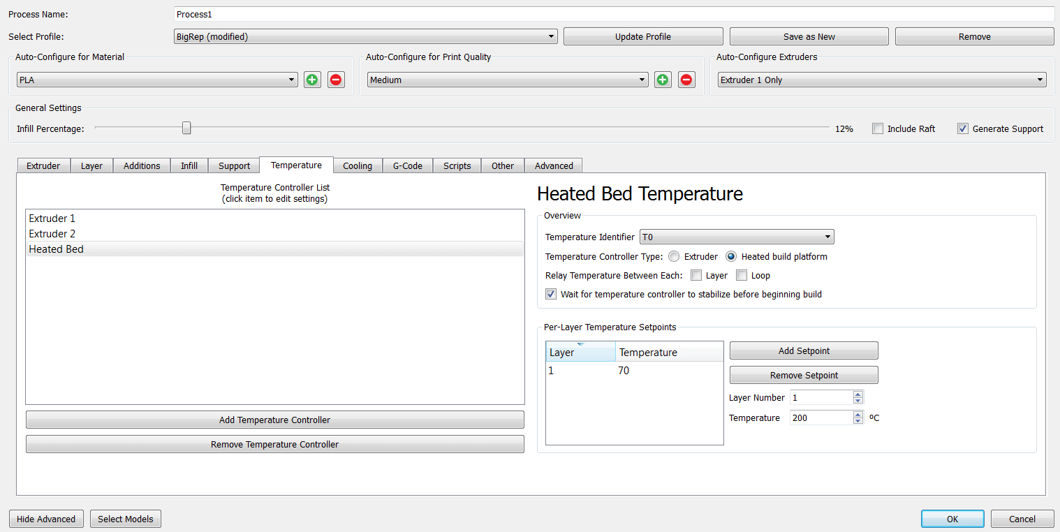
Temperature:
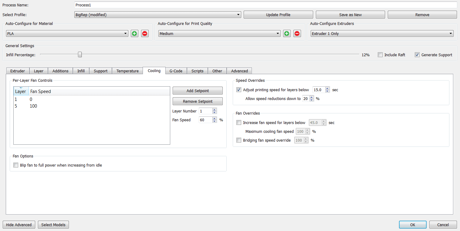
Cooling:
Other:

Advanced:
These are the changes that I made, the rest of the settings I just left by default.
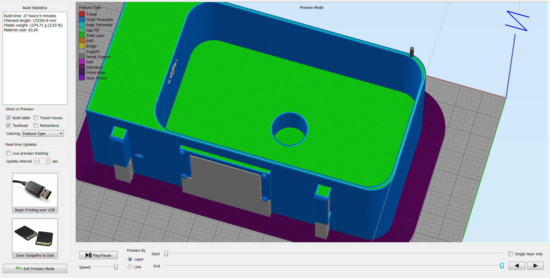
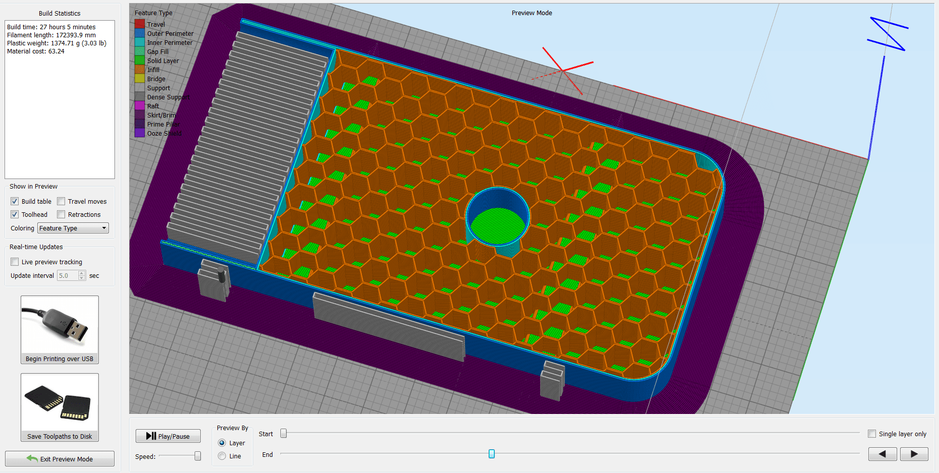
And then press on Prepare to Print . The software will generate the paths, and here we can check if everything is good, before sending the .gcode to the maschine.
Briefly about some of the printer's settings. I used Nozzle Temperature =205 deg.C , and the Bed Temperature =70 deg.C . After I positioned the X, Y, and Z axis , and double checked all the settings, I launched the job!
This is how the raw model looks like:
When I started removing the support and cleaning the model, I realized that this is a BIG pain in the ASS :D
As you can notice, the settings which I used are not really perfect, because the container has some big holes next to the edges. I had in my mind to waterproof it anyway, you can see how I did it in the Moulding &Casting section!
The next 3D printed part was the Net Pot . This is a cup which is designed to hold the seeds in the growing medium. More detailes about the first version of them you can see during my Computer-Aided Design week
This time I will improve the design a bit based on the observations that I made during the experimental stage. The main difference is the size of the empty space, which is increased a lot, to give an easier access for the fog to pass in, and for the roots to go through
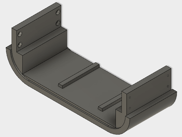
So I just modified the old design, and added one more thing!
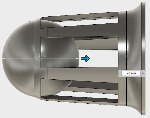
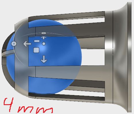
I made a slight fillet on the top part, to make the transition smoother. I also added a ball on the bottom, and used the Move command to move it a bit inside, and leave on the bottom around 2-3mm structure width
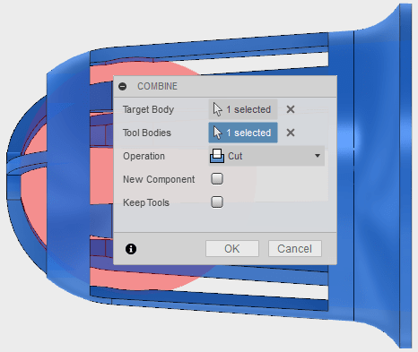
After I used the boolean substraction or Combine function, and I get this nice curviture at the bottom!
Now let's print it!
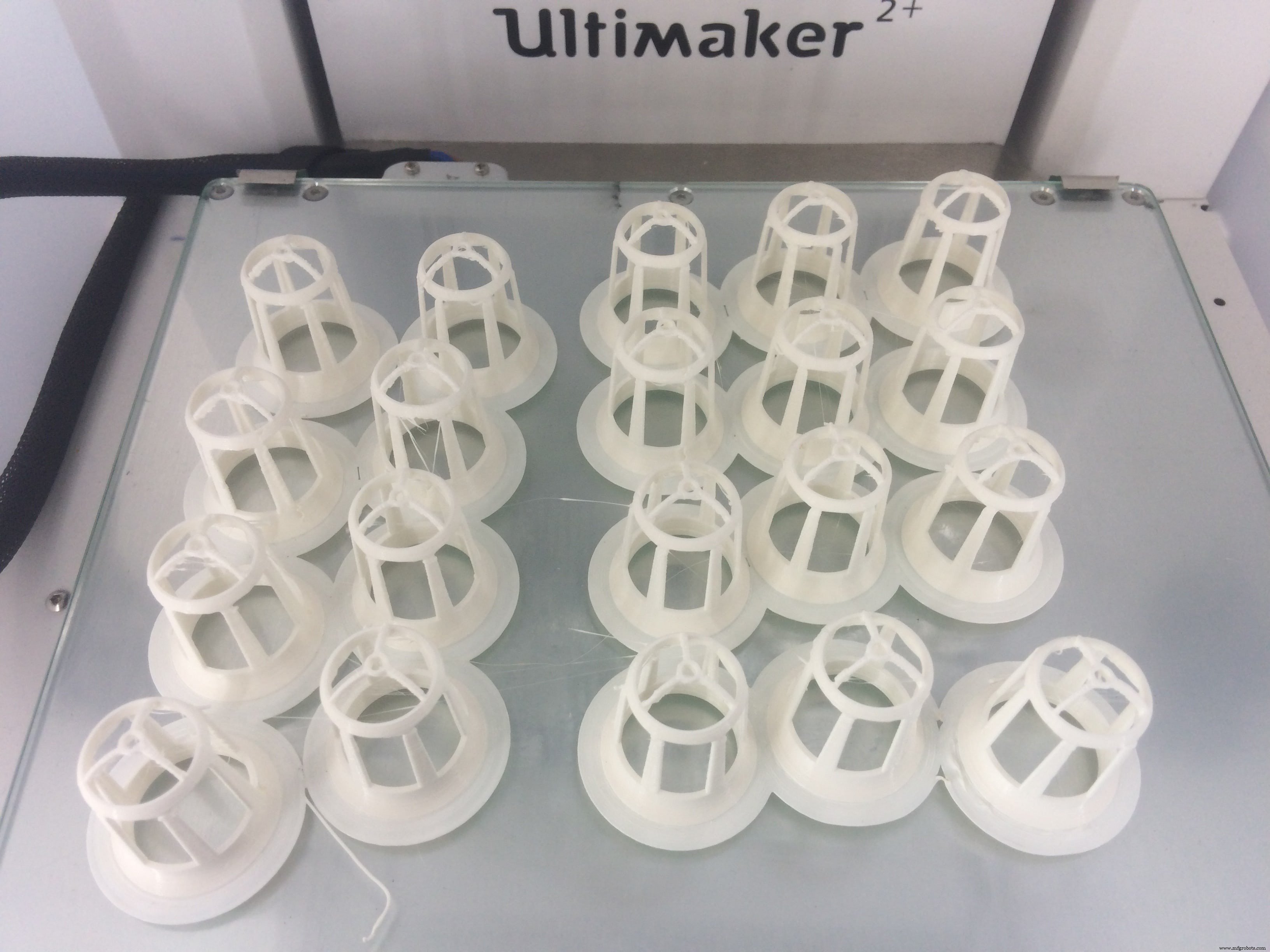
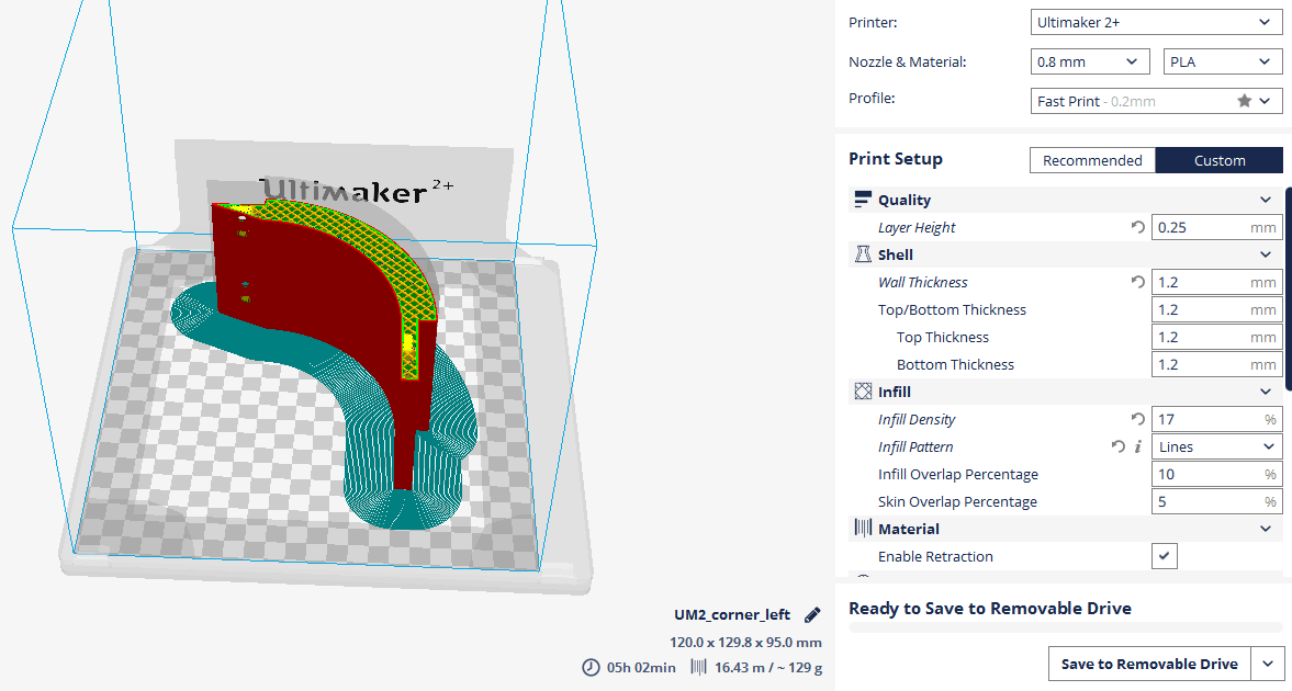
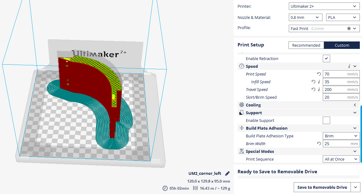
The 3D printer which I used is Ultimaker 2+ . To slice my 3D model, I will use, a very nice software, with an easy interface, and also functional. The material that I am using is PLA filament

After I import my .stl file, these are the settings that I am using:
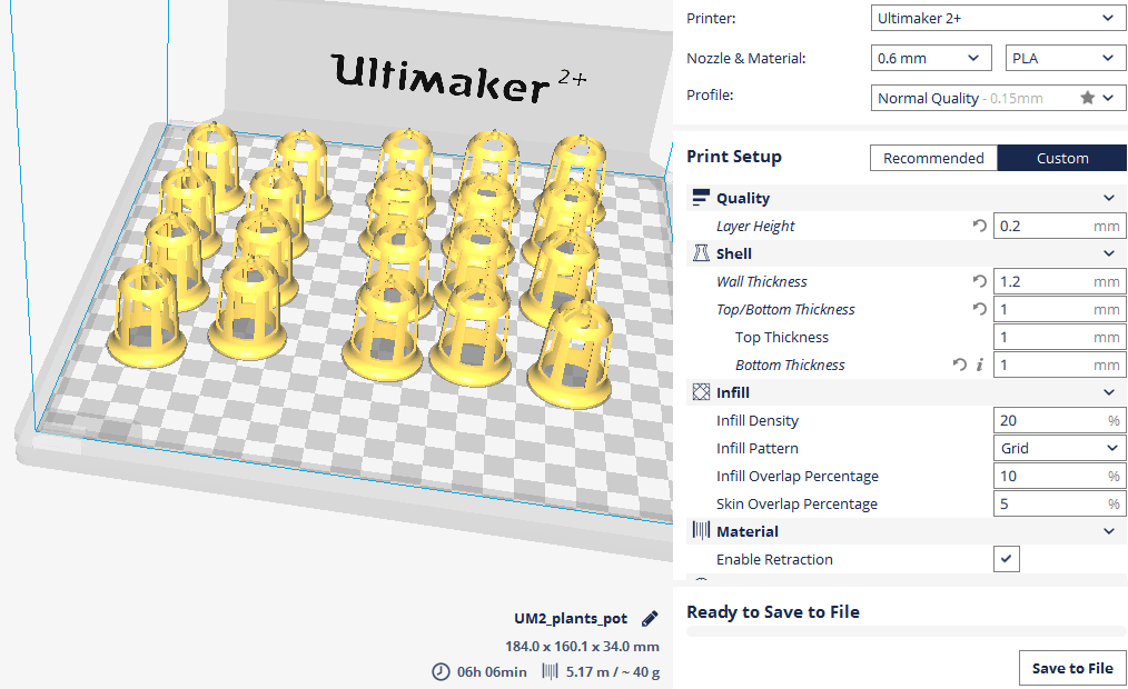
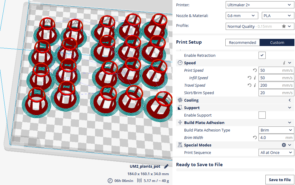
Here it is my little army :D
From the final design of the system, I decided to also 3D print the bottom part. Its a big piece, and I will use the BigRap as well for this.
I wouldn't say that there is anything new about this, because I used the same settings as I used for the water container , and more or less the rest is the same
Here is the preview of the print:
Another thing which I 3D printed are the rounded corners on the top side of the system. I used the Ultimaker for this, and used the following settings:
The trick here was to achieve maximum smoothness on the surface, and I think I got a pretty good result:

Download Files:
GIY System Design (.f3d)
Net Pot Design (.f3d)
2D Design &Laser Cutting
I used the Laser cutting technique to cut acrylic parts which will cover all the inside part of the system, and give it a finished look!
I actually did not design the parts again, I just exported the already created sketches from Fusion 360 as .dxf files . After I exported the file, I used to edit the design before importing it into the lasercut machine

This is how the sketch looks in Fusion360:
Looks like a big mess, but the good part is that everything is parametric! It looks messy because I had to align everything into the right position, and keep the stuff parametric in case I have to make a change later
This is how the final sketch looks in Rhino before lasercutting:
I decided to use a green acrylic piece because it gives an organic look, and combines well with the green plants
For the front and the back cover, I decided to use white color. Its all about the taste, this is the way I see it, and this is how I like it.
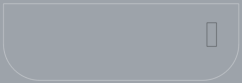
The front and the back cover are very similar, have the same dimensions, except the inside cuts! The front cover has the hole for the LCD Display, here it is:
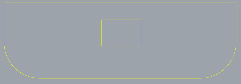
For the back cover, I want to make a hole to have access to power and program the board! This is how it looks:
Another lasercutted piece is on the top! I decided to use a transparent acrylic part, in order for the light to go through! I also designed some additional cuts, to decrease the weight, and give more space for the light to pass! I also measured the width of the RGB LED stripes, and will attach them in a way that there is enough room for the sunlight as well as artificial light!

I finished with the design, and now Let's Laser Cut!
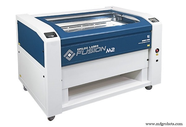
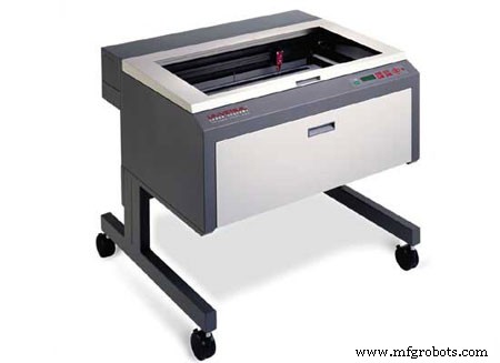
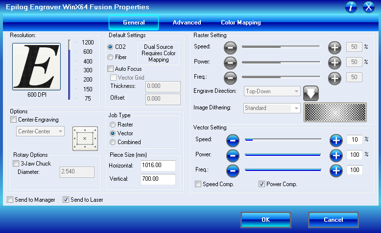
The Laser Cutter that we are using here in FabLab is Epilog Fusion 60Watt, a CO2 lasercutter with a working area of 1016 x 711 mm. It can cut and ingrave materials like wood, cardboard, acrylic or other engineered plastics.
Because I used the same material for all the pieces, plexiglass 5mm , I used the same settings for all of them!
Download Files:
Front / Back Cover (.dxf)
Plant Holder (.dxf)
LED Light Holder (.dxf)
CNC Milling
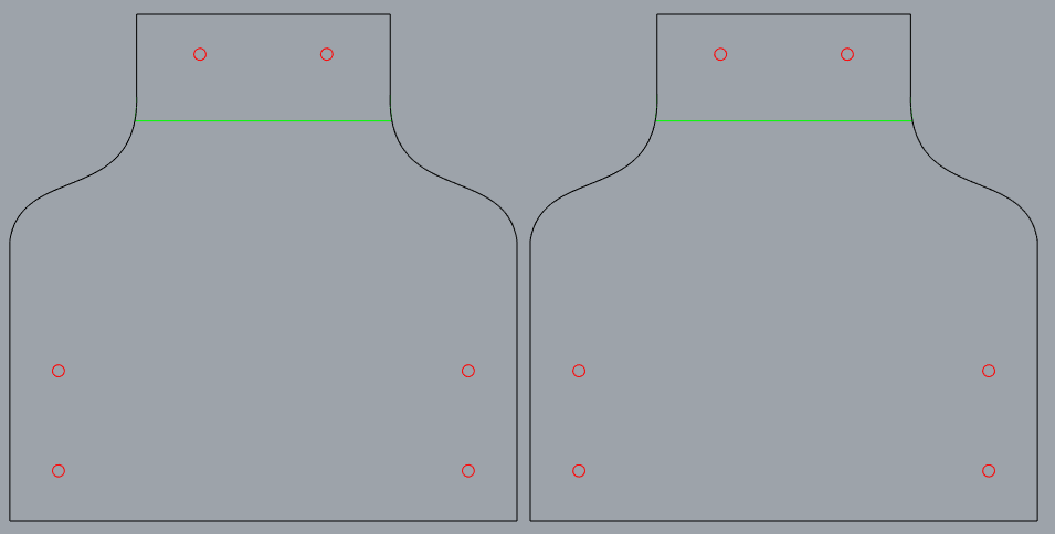
Because I wanted to integrate in my system all the skills and techniques that I learned, I also have a piece of structure to CNC mill. I did not design it again, but I exported the .dxf file from Fusion360 sketch!
To cut my design, I will be using the big CNC monster.
A CNC (computer numerically controlled) is a machine that uses a cutting bit that rotates at a very high speed to remove material from a part.
The machine reads a pre‐programed computer file telling it where and how to cut, usually .GCode file. A cutting bit is rotated at a very high RPM by a spindle motor, which can move the bit up and down. This mechanism is moved left, right, front, and back by a cross arm. The machine is therefore known as a three‐axis router because it can move on the X, Y &Z axis. The machine can do two dimensional cutouts and etching, as well as three‐dimensional relief work.
In FabLab Kamp-Lintfort we have a CNC portal milling machine by e(sign:Easy Worker MasterPro 2513.

It’s working area is 2600 x 1400 x 300mm and it comes with a vacuum table. We primarily use it for wood milling but with its HSD Spindel (3.9KW; 24.000U/min) it is also capable to mill metals easily.
The material which I will be using is 18mm Plywood
At first, I place the wood sheet on the CNC bed, and after I aligned it, switch on the vacuum. After I exported the .dxf file, I used to edit the design before importing it into the machine CAM software.
First, I have to HOME the machine!
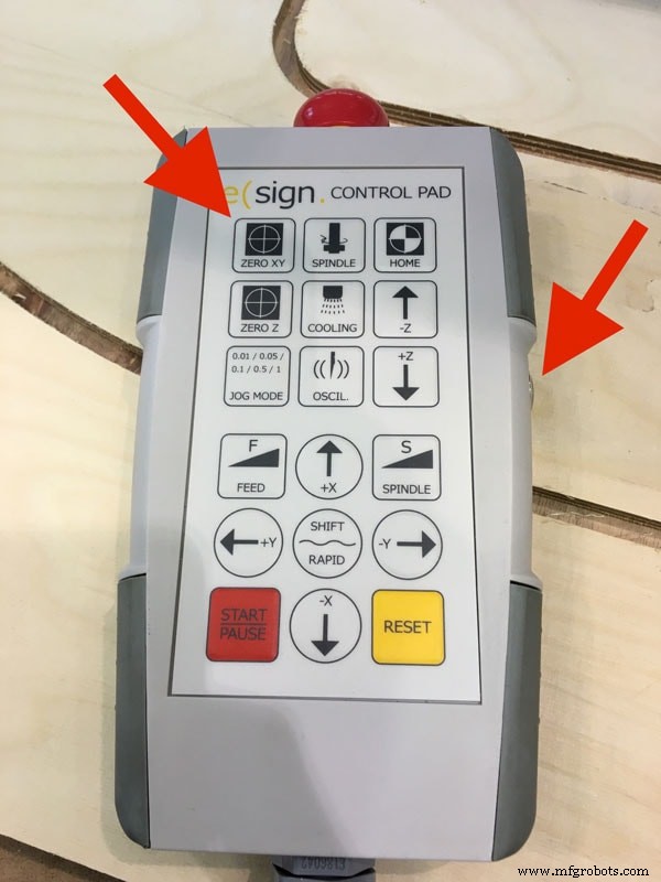
To set the X, Y and Z Zero Positions, I home the machine by pressing the home button in the software (or on the remote control).
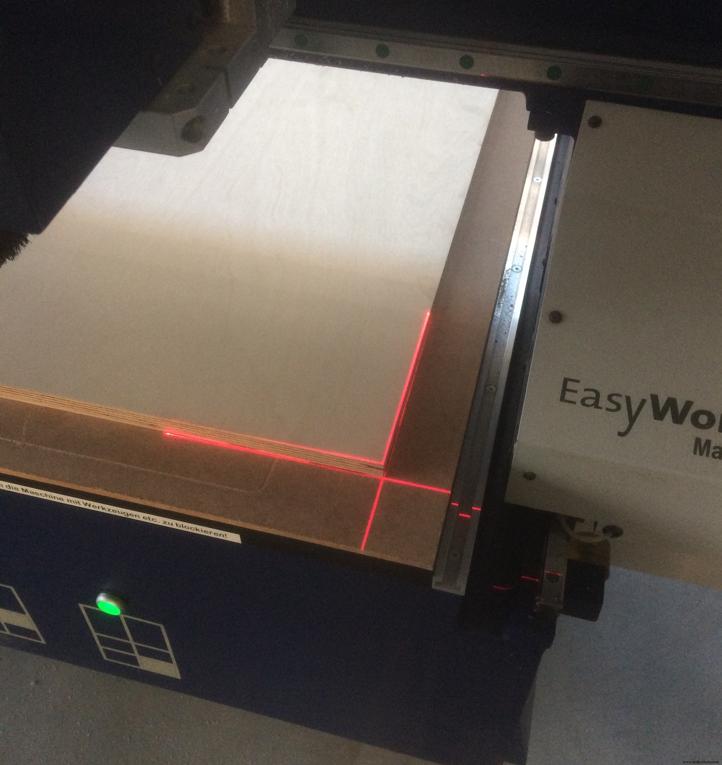
At first, I can set my zero X and Y roughly aligned to one of the corners of the bed. We also tried to use the laser for this, but all the time when simulating the process, it was showing collisions, because the zero was going out of the working area
Now I have to find the Z axis, which I do using the special tool which comes with the machine:
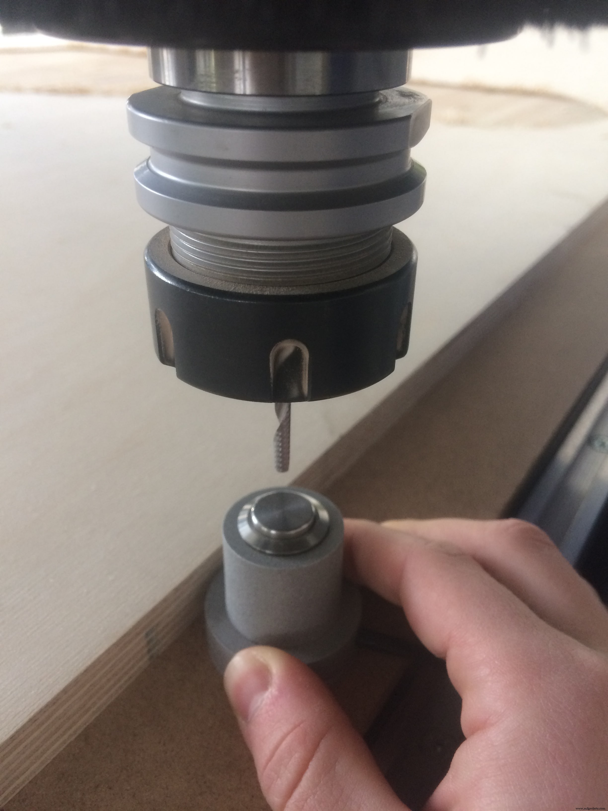
Important thing is to place it on the bed of the machine!
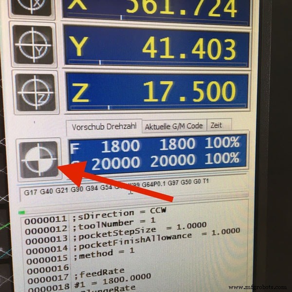
Now I can launch the first job, which is making the engraving. These are the settings which I used:
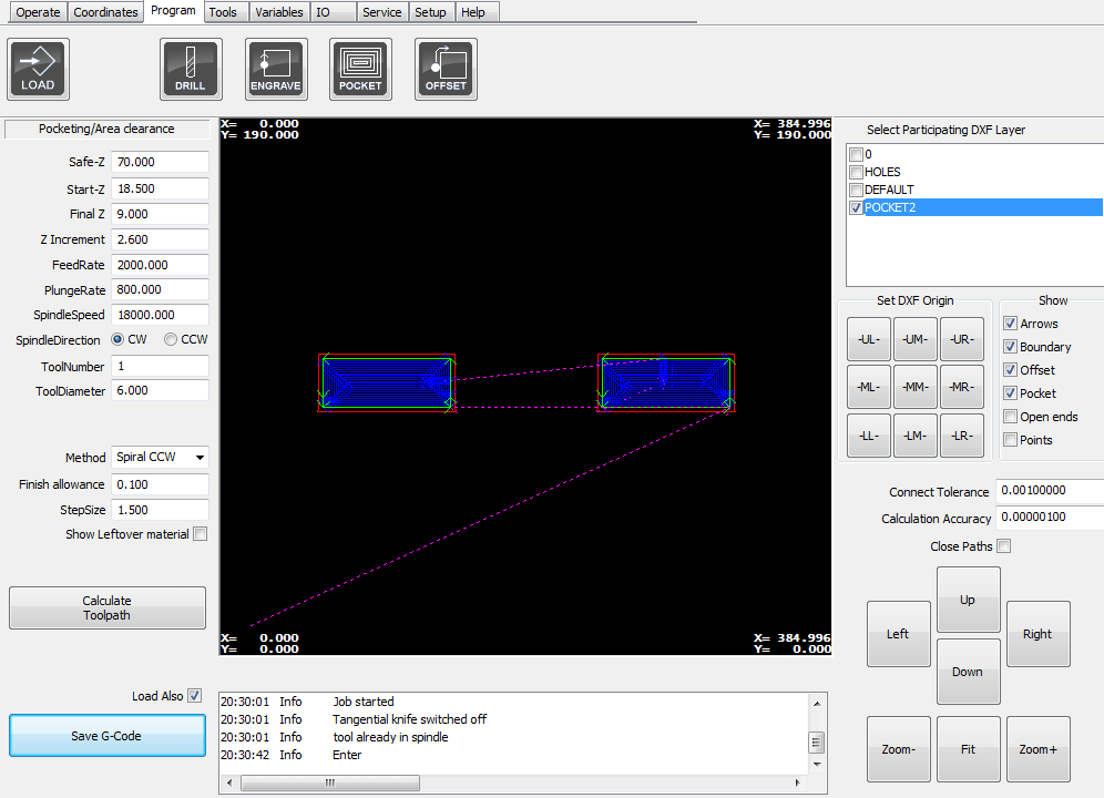
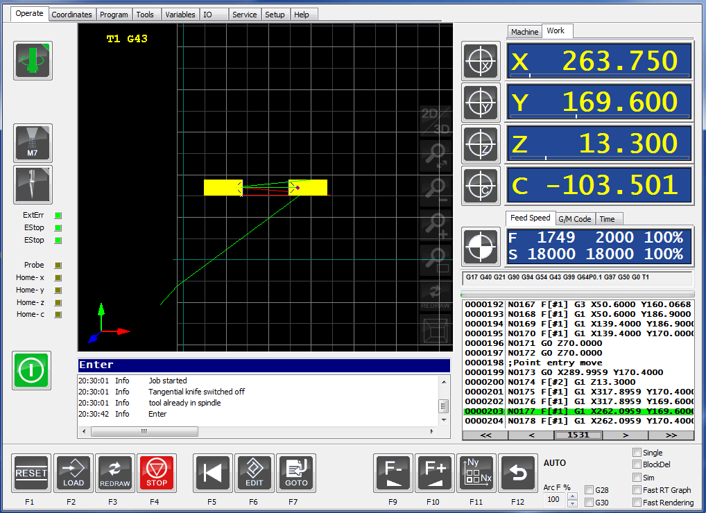
I press Calculate Toolpath to simulate the job and make sure that there are no collisions! After I save the .GCode , and launch the job, I get this window:
Now I can launch the outside cut:
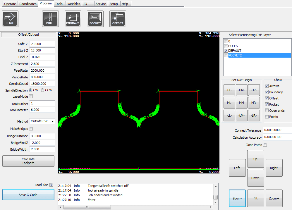

This is what I get after the job is done:
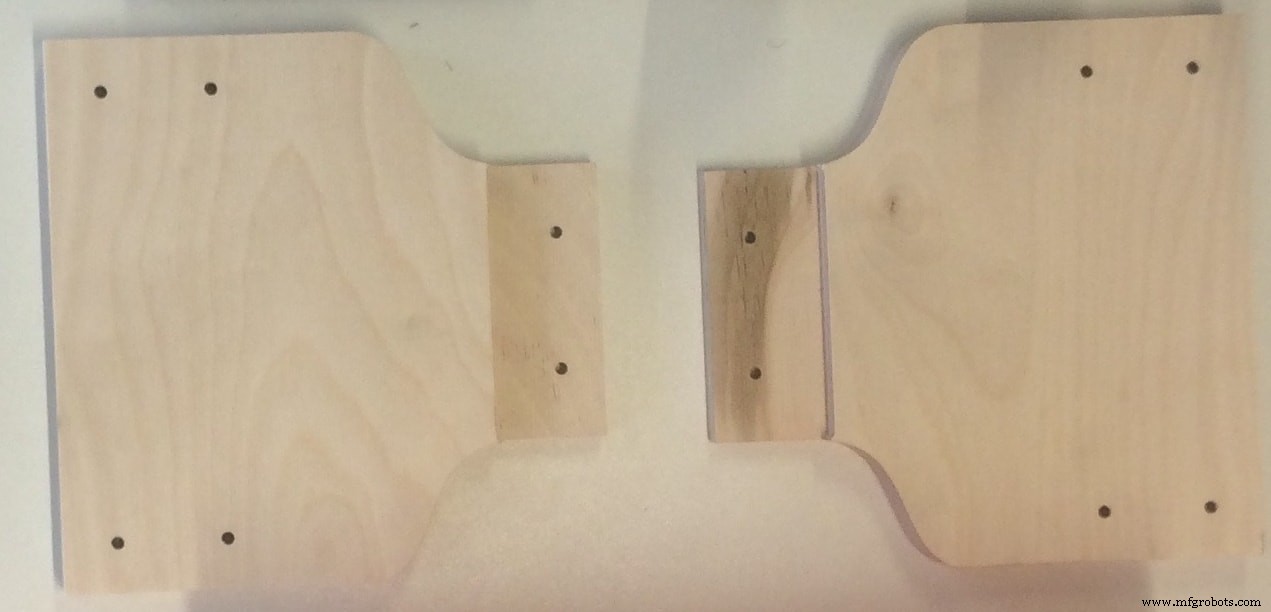
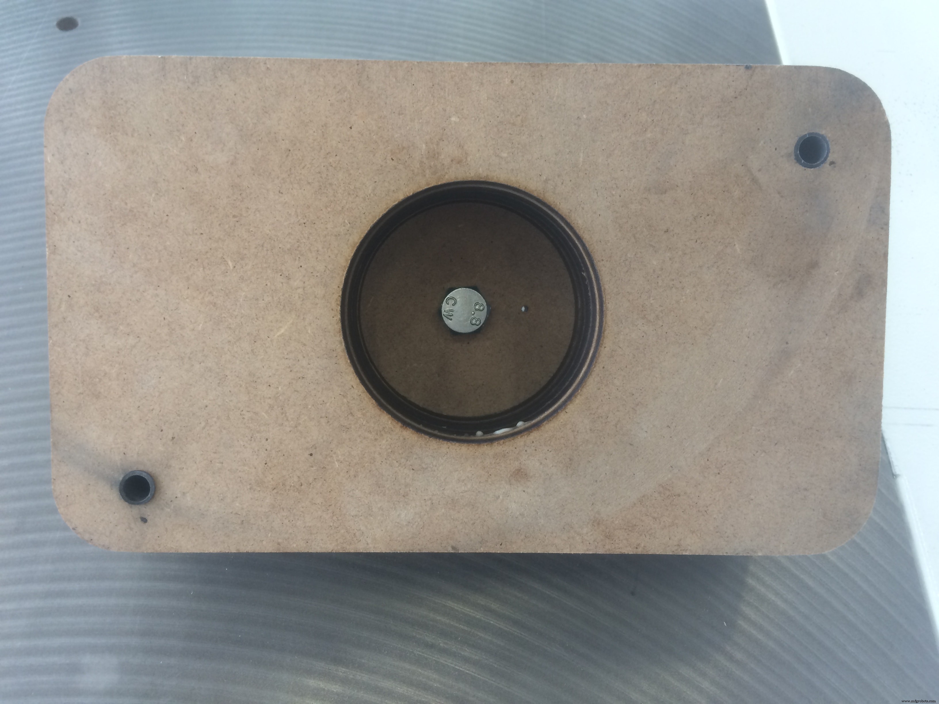
Another piece which I had to mill is used for the Moulding &Casting section!
I prepared the mould to waterproof my water container. Here is the design:

There is nothing new about this. I used exactly the same settings as above. The only thing is the material thickness was 10mm wood , and I had to cut 7 pieces, to glue them together later and prepare my mould!
Download Files:
Structure Walls (.dxf)
Mould (.dxf)
Moulding &Casting
I used this technique in order to prepare a water container, to waterproof my existing container! I see it as a thin layer of material (a smaller container) which can be easily removable!
This is the result from the previous section CNC Milling
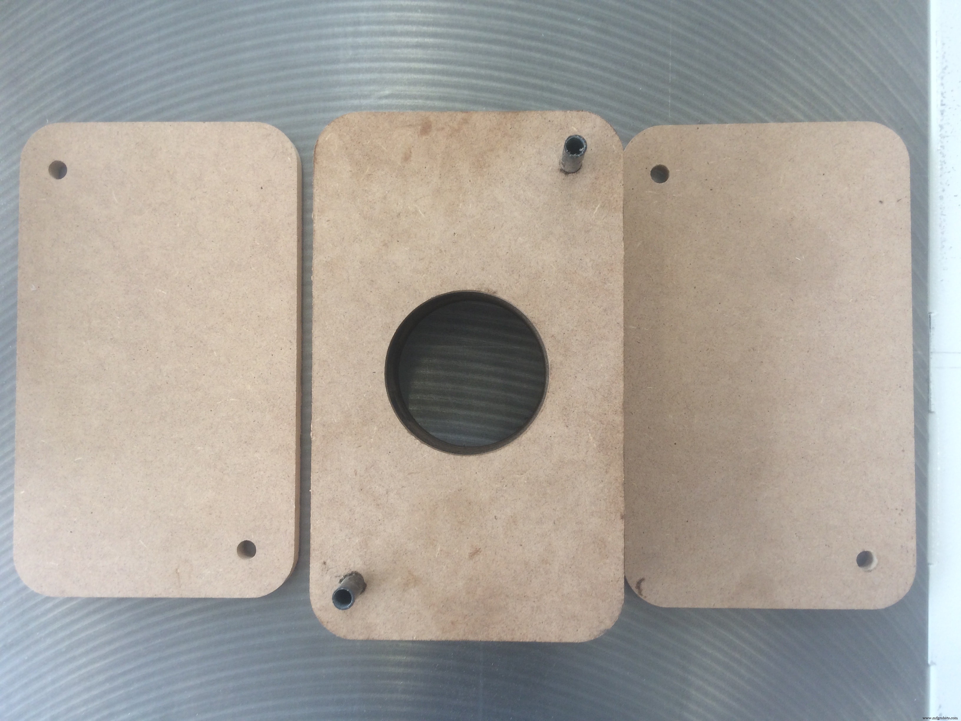
I cut 7 identical pieces, and aligned them using the reference holes! I also cut a big hole in the middle of 5 bottom pieces , in order to place the air pump inside, and easily remove the cast later.
After I glued all the pieces together, and fixed them, this is how it looks:
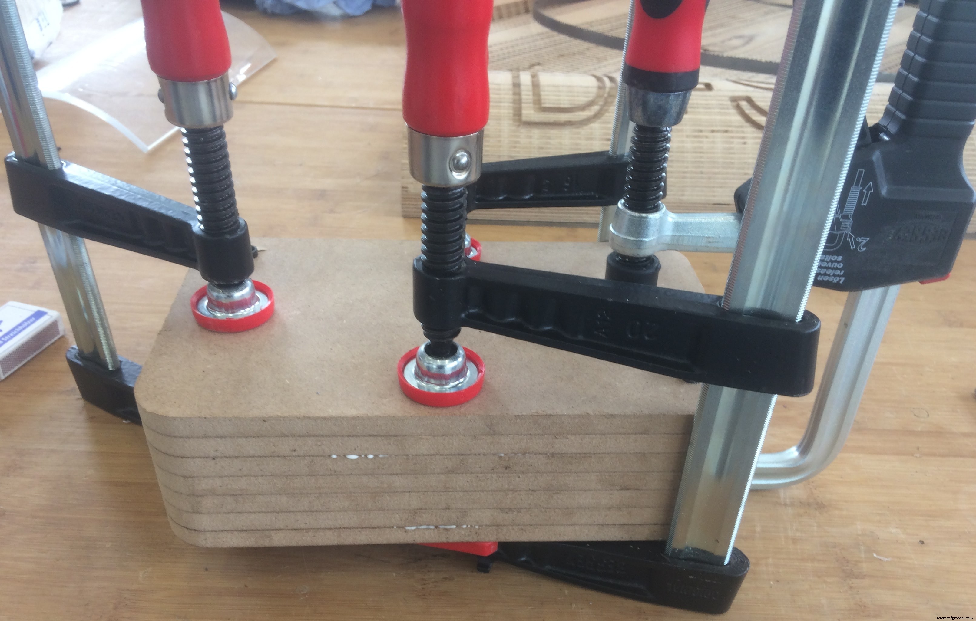
While waiting for the glue to dry out, I prepared a little plastic "thing" (do not know how to call it :D) for the pump. The idea is to be able to screw it on my mould, and remove it whenever I want!
When the mould is ready, this is how it looks:
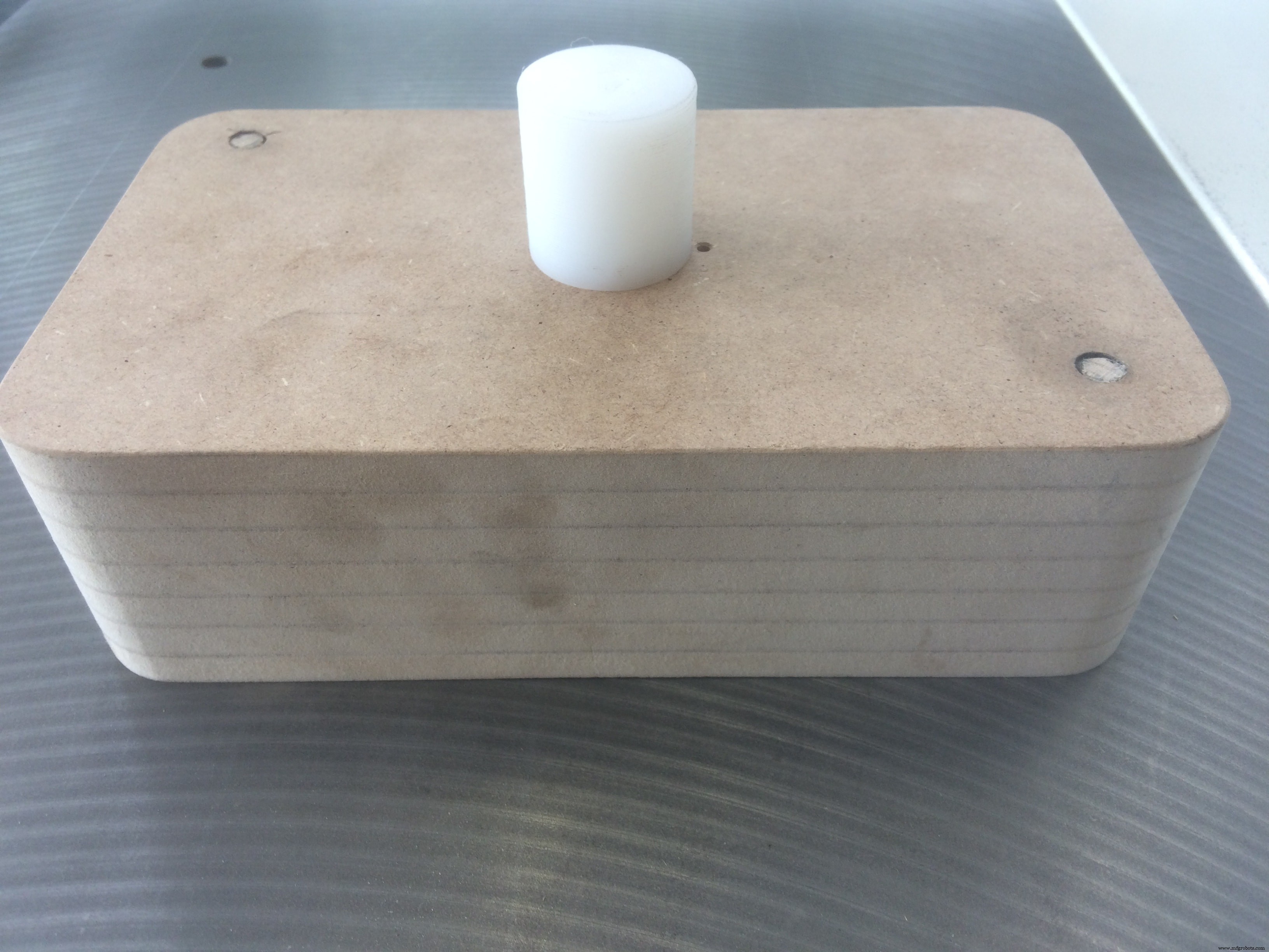
And the back side:
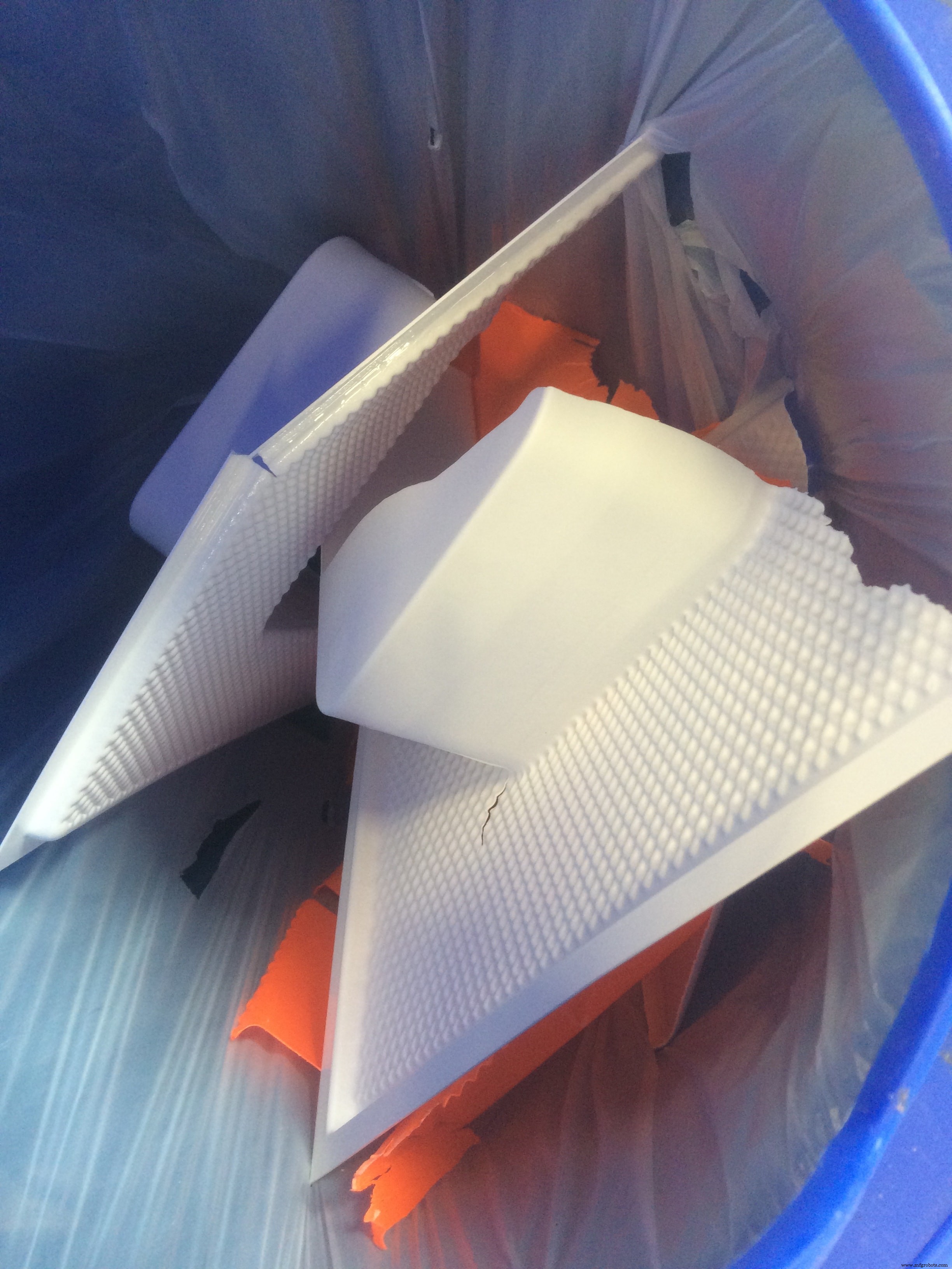
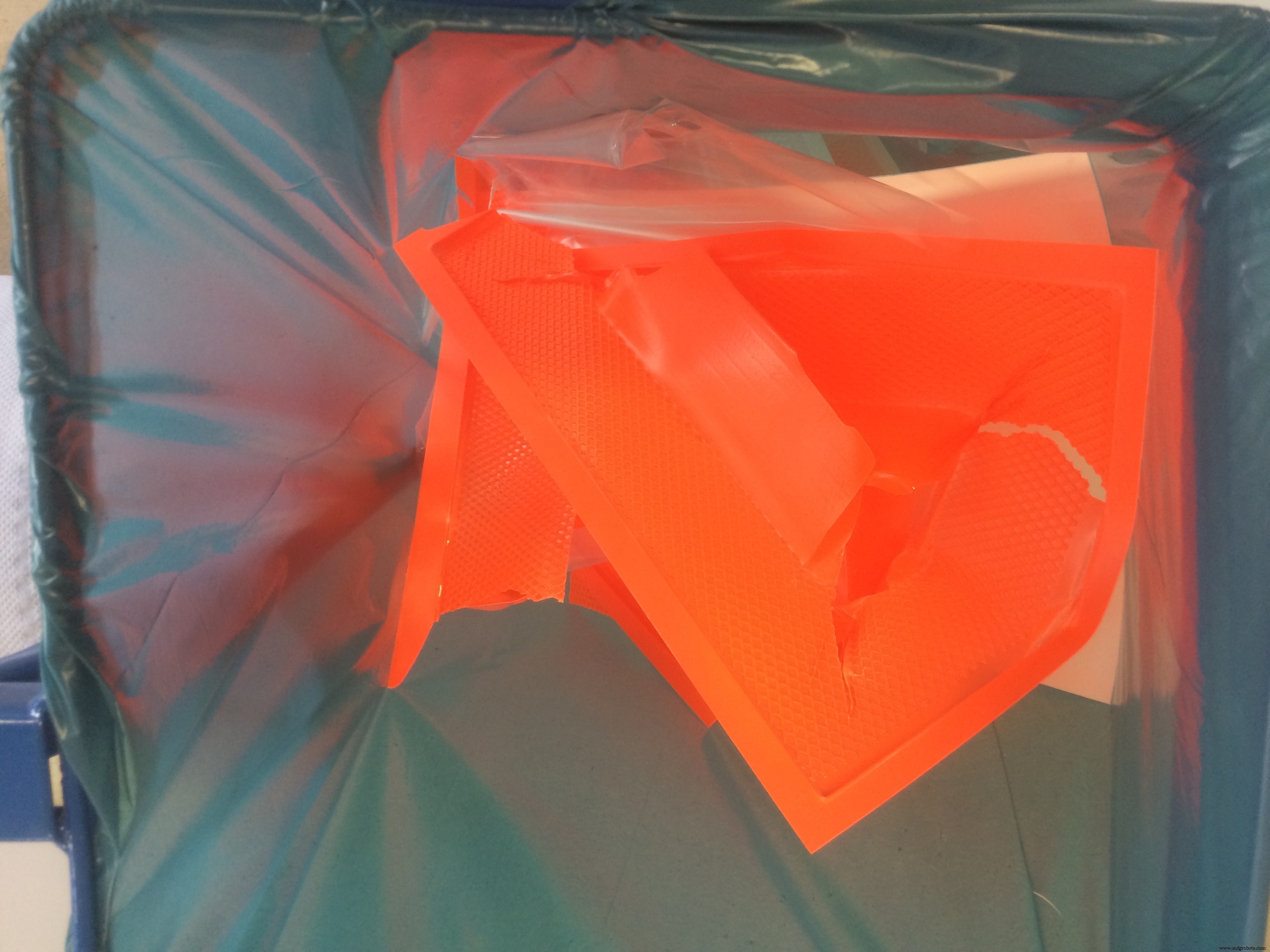
I am ready to vacuum cast!
I used a vacuum machine available in our FabLab Kamp-Lintfort called Formech – Manual Vacuum Forming Machine
The thing is that I tried to do it many times, and all the time I could not remove the mould without breaking the cast! After several hours of trials, I came up with a solution! First, I vacuum casted one thin layer of material, and without removing it, I will cast the actual container on top of it. The first thin layer is slippery, and If I spray it with silicon, it will allow me to remove the mould way easier
After I let the silicon to dry a bit, I can cast the actual layer!
And here we are!!!
A hero shot for those who may thing that it was easy
Putting All Together
Now, let's put everything together! I will start by assembling the structure. Put next to me all the necessary tools:
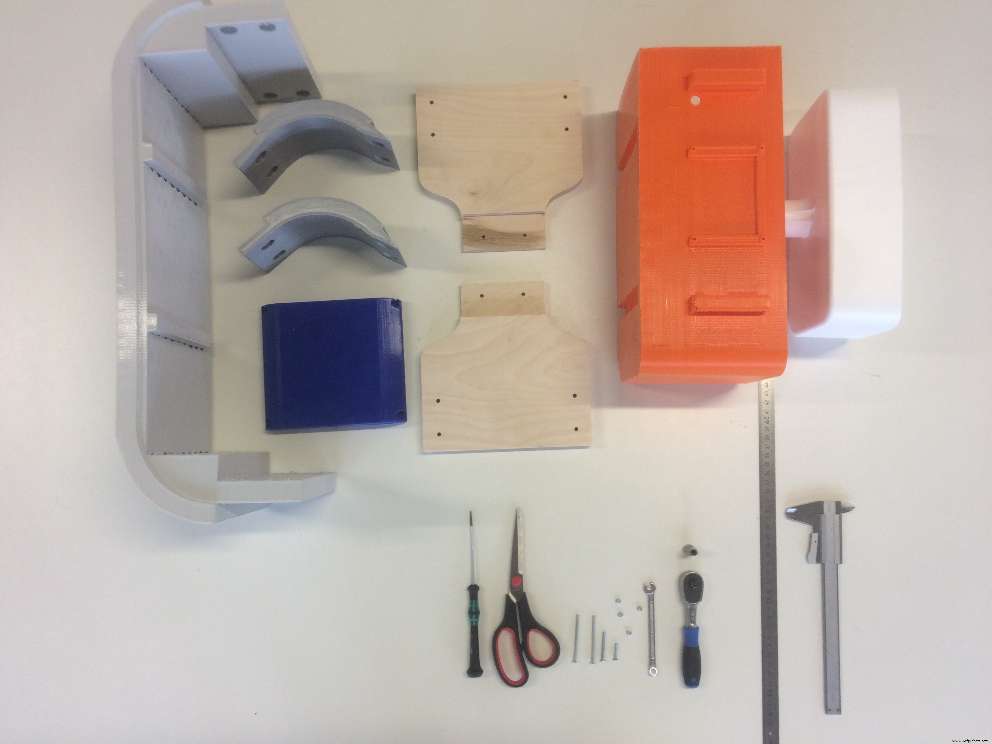
A short animation of the process:
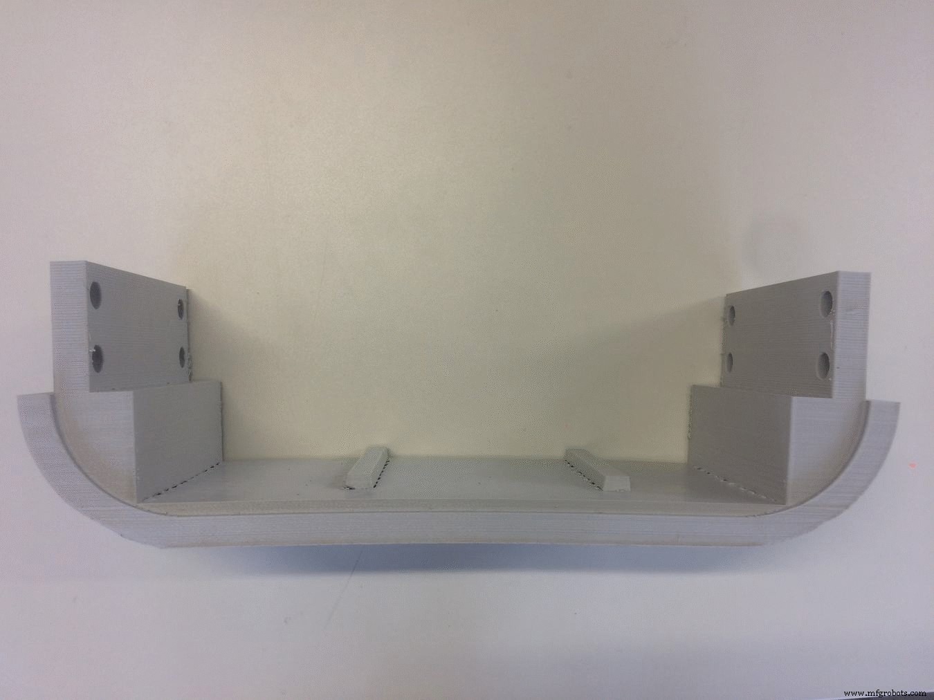
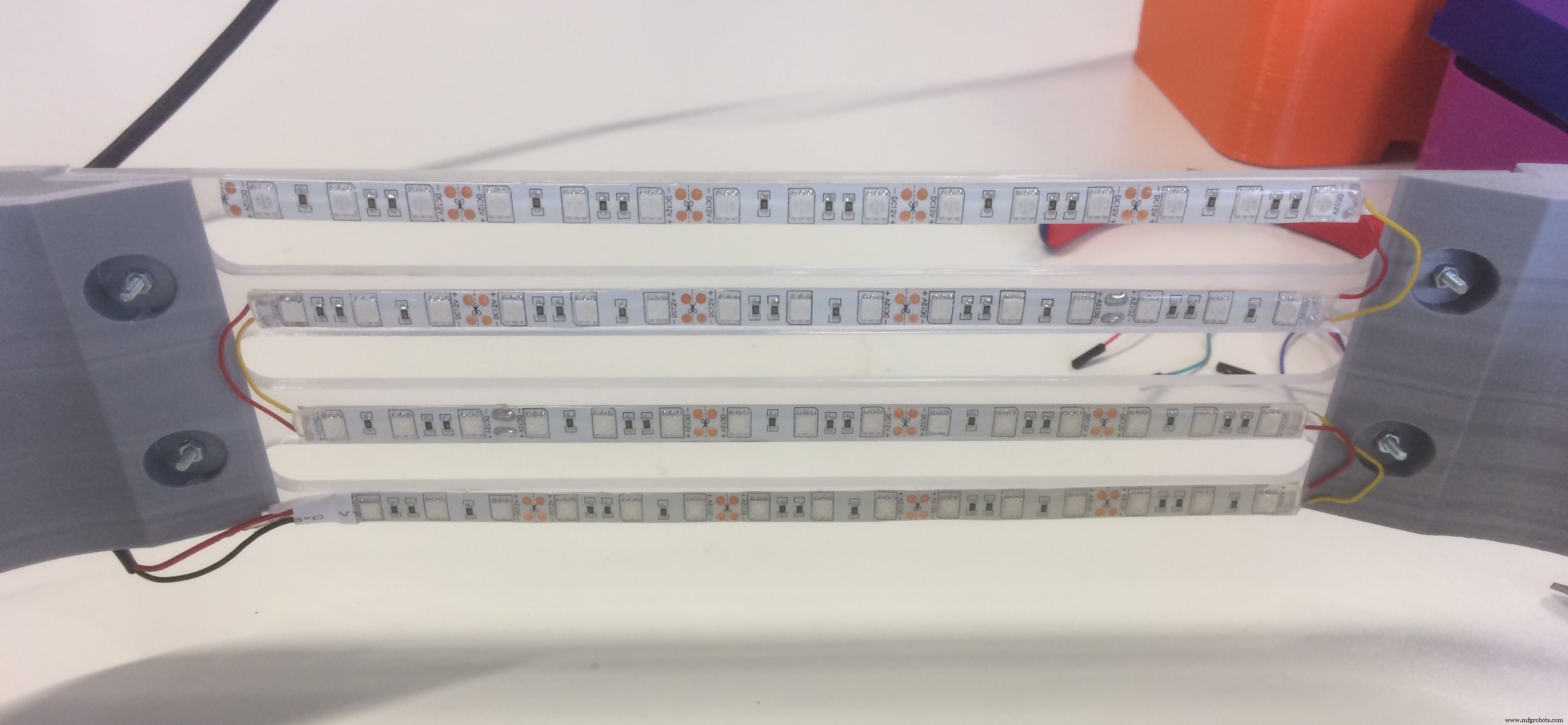
To assemble the lights, I cut the RGB LED stripes into 4 pieces (I measured the length in advance), and soldered them accordingly!
After I connected all the sensors, and managed the wiring, I fixed the board in the electronics section
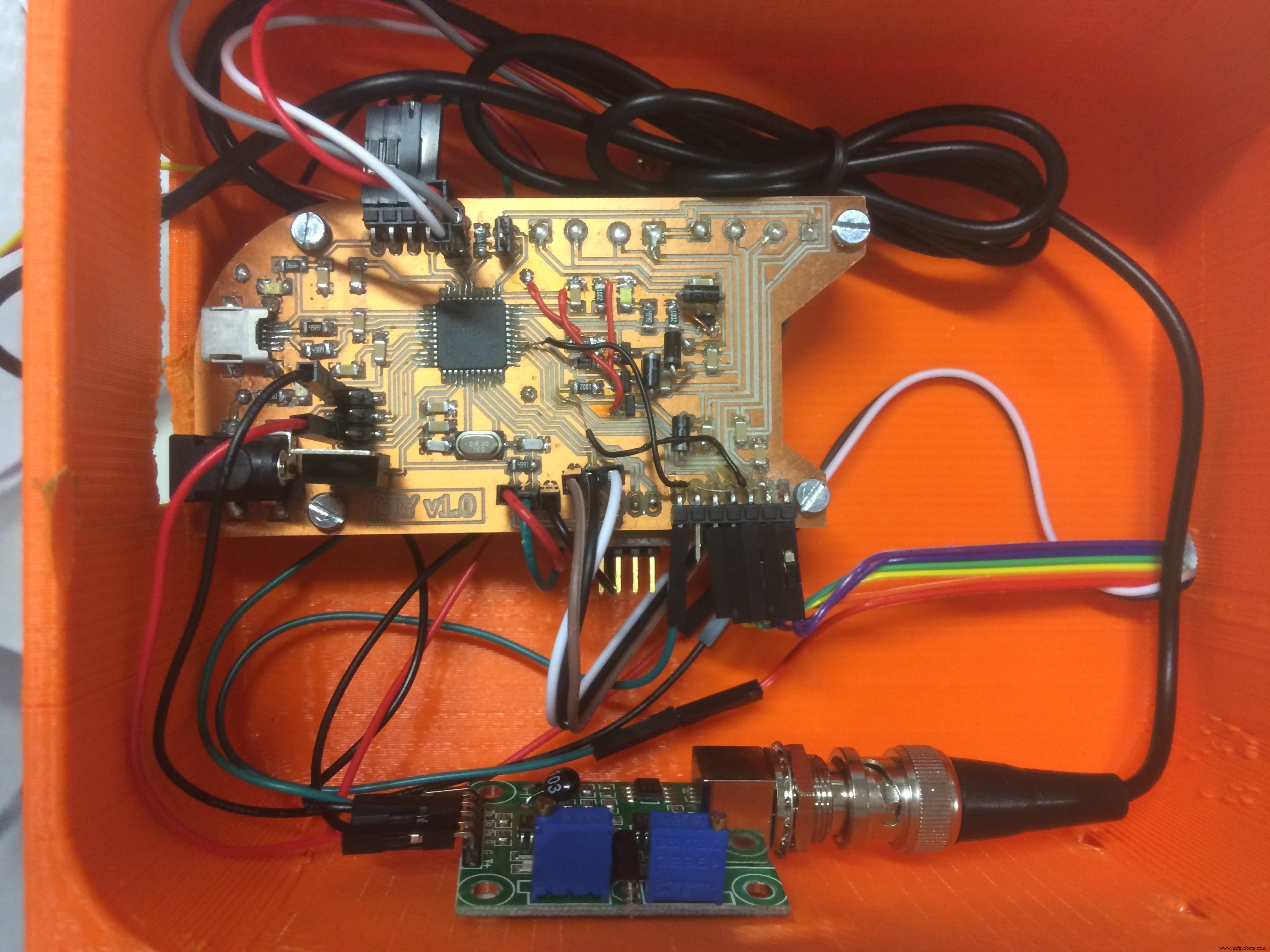
And here it is the system!!! Everything assembled, nice looking growing system GIY
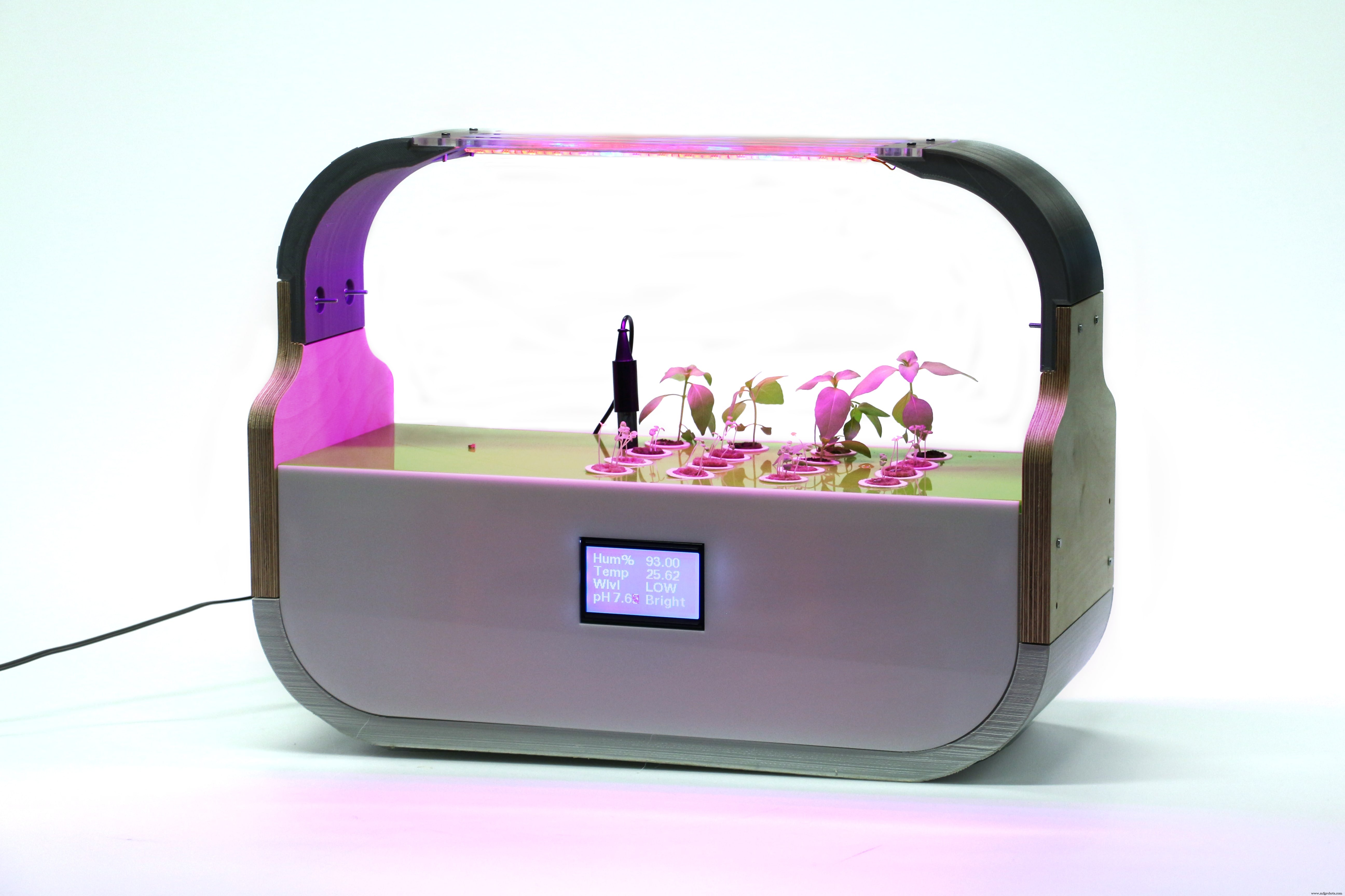
A HERO shot during the working process!
Final Presentation Video
© 2017 Albot Dima. All rights reserved | Albot.Dumitru@hsrw.org
This work is licensed under a Creative Commons Attribution-NonCommercial-ShareAlike 4.0 International License.

For more details about the project, please visit the official source:
http://archive.fabacademy.org/2017/fablabkamplintfort/students/396/final.html
Code
- GIY Board - CODE
- GIY BOARD - LCD + LIGHT CODE
GIY Board - CODEArduino
#include "dht.h"#include "U8glib.h"#include#include #define DHT11_PIN 2 // what digital pin we're connected to#define ONE_WIRE_BUS 3#define WATER_LEVEL A4#define LDR_PIN A3#define PH_PIN A5#define GROW_LIGHT 10#define FOG_PUMP 13int waterLevel;int LightLevel;int pH;dht DHT;OneWire oneWire(ONE_WIRE_BUS); DallasTemperature waterTemp(&oneWire);U8GLIB_ST7920_128X64 u8g(4, 12, 6, U8G_PIN_NONE);const unsigned char logo [] PROGMEM ={0xFF, 0xFF, 0xFF, 0xFE, 0x7F, 0xFF, 0xFF, 0xFF, 0x00, 0x00, 0x00, 0x00, 0x00, 0x00, 0x00, 0x00,0xFF, 0xFF, 0xFF, 0x00, 0x00, 0xFF, 0xFF, 0xFF, 0x00, 0x00, 0x00, 0x00, 0x00, 0x00, 0x00, 0x00,0xFF, 0xFF, 0xF8, 0x00, 0x00, 0x1F, 0xFF, 0xFF, 0x00, 0x00, 0x00, 0x00, 0x00, 0x00, 0x00, 0x00,0xFF, 0xFF, 0xC0, 0x00, 0x00, 0x03, 0xFF, 0xFF, 0x00, 0x00, 0x00, 0x00, 0x00, 0x00, 0x00, 0x00,0xFF, 0xFF, 0x00, 0x00, 0x00, 0x00, 0xFF, 0xFF, 0x00, 0x00, 0x00, 0x00, 0x00, 0x00, 0x00, 0x00,0xFF, 0xFE, 0x00, 0x03, 0xC0, 0x00, 0x7F, 0xFF, 0x00, 0x00, 0x00, 0x00, 0x00, 0x00, 0x00, 0x00,0xFF, 0xF8, 0x00, 0x07, 0xE0, 0x00, 0x3F, 0xFF, 0x00, 0x00, 0x00, 0x00, 0x00, 0x00, 0x00, 0x00,0xFF, 0xF0, 0x00, 0x1F, 0xF8, 0x00, 0x0F, 0xFF, 0x00, 0x00, 0x00, 0x00, 0x00, 0x00, 0x00, 0x00,0xFF, 0xE0, 0x00, 0x3F, 0xFE, 0x00, 0x07, 0xFF, 0x00, 0x00, 0x00, 0x00, 0x00, 0x00, 0x00, 0x00,0xFF, 0xC0, 0x00, 0x18, 0x1F, 0x00, 0x03, 0xFF, 0x00, 0x00, 0x00, 0x00, 0x00, 0x00, 0x00, 0x00,0xFF, 0x80, 0x00, 0x00, 0x03, 0xC0, 0x01, 0xFF, 0x00, 0x00, 0x00, 0x00, 0x00, 0x00, 0x00, 0x00,0xFF, 0x00, 0x00, 0x00, 0x00, 0xF0, 0x00, 0xFF, 0x00, 0x00, 0x00, 0x00, 0x00, 0x00, 0x00, 0x00,0xFE, 0x00, 0x00, 0x00, 0x00, 0x7C, 0x00, 0x7F, 0x00, 0x00, 0x00, 0x00, 0x00, 0x00, 0x00, 0x00,0xFC, 0x00, 0x00, 0x00, 0x00, 0x3E, 0x00, 0x7F, 0x00, 0x00, 0x00, 0x00, 0x00, 0x00, 0x00, 0x00,0xFC, 0x03, 0x80, 0x00, 0x00, 0x3F, 0x80, 0x3F, 0x00, 0x00, 0x00, 0x00, 0x00, 0x00, 0x00, 0x00,0xF8, 0x07, 0xE0, 0x00, 0x00, 0x1F, 0xE0, 0x1F, 0x00, 0x00, 0x00, 0x00, 0x00, 0x00, 0x00, 0x00,0xFC, 0x1F, 0xF0, 0x00, 0x00, 0x1F, 0xF0, 0x1F, 0x00, 0x00, 0x00, 0x00, 0x00, 0x00, 0x00, 0x00,0xF0, 0x3F, 0xF0, 0x00, 0x00, 0x1F, 0xFC, 0x0F, 0x00, 0x00, 0x00, 0x00, 0x00, 0x00, 0x00, 0x00,0xF0, 0xFF, 0xF0, 0x00, 0x00, 0x1F, 0xFF, 0x0F, 0x00, 0x00, 0x00, 0x00, 0x00, 0x00, 0x00, 0x00,0xE0, 0xFF, 0xF0, 0x00, 0x00, 0x3F, 0xFF, 0x07, 0x00, 0x00, 0x00, 0x00, 0x00, 0x00, 0x00, 0x00,0xE0, 0xFF, 0xF0, 0x00, 0x00, 0x3F, 0xFF, 0x07, 0x00, 0x00, 0x00, 0x00, 0x00, 0x00, 0x00, 0x00,0xC0, 0xFF, 0xF8, 0x00, 0x00, 0x7F, 0xFF, 0x03, 0x00, 0x00, 0x00, 0x00, 0x00, 0x00, 0x00, 0x00,0xC0, 0xFF, 0xFC, 0x00, 0x00, 0xFF, 0xFF, 0x03, 0x00, 0x00, 0x00, 0x00, 0x00, 0x00, 0x00, 0x00,0xC0, 0xFF, 0xFF, 0x00, 0x01, 0xFF, 0xFF, 0x03, 0x00, 0x00, 0x00, 0x00, 0x00, 0x00, 0x00, 0x00,0x80, 0xFF, 0xFF, 0xC0, 0x07, 0xFF, 0xFF, 0x01, 0x00, 0x00, 0x00, 0x00, 0x00, 0x00, 0x00, 0x00,0x80, 0xFF, 0xFF, 0xFF, 0xFF, 0xFF, 0xFF, 0x01, 0x00, 0x00, 0x00, 0x00, 0x00, 0x00, 0x00, 0x00,0x80, 0xFF, 0xFF, 0xFF, 0xFF, 0xFF, 0xFF, 0x01, 0x00, 0x00, 0x00, 0x00, 0x00, 0x00, 0x00, 0x00,0x80, 0xFF, 0xFF, 0xFF, 0xFF, 0xFF, 0xFF, 0x01, 0x00, 0x00, 0x00, 0x00, 0x00, 0x00, 0x00, 0x00,0x80, 0xFE, 0x1F, 0xFF, 0xFF, 0xF0, 0x3C, 0x01, 0x00, 0x00, 0x00, 0x00, 0x00, 0x00, 0x00, 0x00,0x80, 0xF8, 0x03, 0xFF, 0xFF, 0xC0, 0x10, 0x01, 0x00, 0x00, 0x00, 0x00, 0x00, 0x00, 0x00, 0x00,0x80, 0xF0, 0x01, 0xFF, 0xFF, 0x80, 0x00, 0x01, 0x00, 0x00, 0x00, 0x00, 0x00, 0x00, 0x00, 0x00,0x00, 0xF0, 0x00, 0xFF, 0xFF, 0x00, 0x00, 0x01, 0x00, 0x00, 0x00, 0x00, 0x00, 0x00, 0x00, 0x00,0x00, 0xE0, 0x00, 0x7F, 0xFE, 0x00, 0x00, 0x01, 0x00, 0x00, 0x00, 0x00, 0x00, 0x00, 0x00, 0x00,0x80, 0xE0, 0x00, 0x3F, 0xFC, 0x00, 0x00, 0x01, 0x00, 0x00, 0x00, 0x00, 0x00, 0x00, 0x00, 0x00,0x80, 0xE0, 0x00, 0x1F, 0xFC, 0x00, 0x00, 0x01, 0x00, 0x00, 0x00, 0x00, 0x00, 0x00, 0x00, 0x00,0x80, 0xE0, 0x00, 0x1F, 0xF8, 0x00, 0x00, 0x01, 0x00, 0x00, 0x00, 0x00, 0x00, 0x00, 0x00, 0x00,0x80, 0xE0, 0x00, 0x0F, 0xF8, 0x00, 0x00, 0x01, 0x00, 0x00, 0x00, 0x00, 0x00, 0x00, 0x00, 0x00,0x80, 0xE0, 0x00, 0x0F, 0xF0, 0x00, 0x00, 0x01, 0x00, 0x00, 0x00, 0x00, 0x00, 0x00, 0x00, 0x00,0x80, 0xE0, 0x00, 0x0F, 0xF0, 0x00, 0x01, 0x01, 0x00, 0x00, 0x00, 0x00, 0x00, 0x00, 0x00, 0x00,0x80, 0xE0, 0x00, 0x07, 0xF0, 0x00, 0x07, 0x01, 0x00, 0x00, 0x00, 0x00, 0x00, 0x00, 0x00, 0x00,0xC0, 0xF0, 0x00, 0x07, 0xF0, 0x00, 0x07, 0x03, 0x00, 0x00, 0x00, 0x00, 0x00, 0x00, 0x00, 0x00,0xC0, 0xF0, 0x00, 0x07, 0xF0, 0x00, 0x0F, 0x03, 0x00, 0x00, 0x00, 0x00, 0x00, 0x00, 0x00, 0x00,0xC0, 0xF8, 0x00, 0x07, 0xF0, 0x00, 0x0F, 0x03, 0x00, 0x00, 0x00, 0x00, 0x00, 0x00, 0x00, 0x00,0xC0, 0xF8, 0x00, 0x07, 0xF0, 0x00, 0x1F, 0x07, 0x00, 0x00, 0x00, 0x00, 0x00, 0x00, 0x00, 0x00,0xE0, 0xFC, 0x00, 0x07, 0xF0, 0x00, 0x1F, 0x07, 0x00, 0x00, 0x00, 0x00, 0x00, 0x00, 0x00, 0x00,0xE0, 0xFE, 0x00, 0x0F, 0xF0, 0x00, 0x3F, 0x07, 0x00, 0x00, 0x00, 0x00, 0x00, 0x00, 0x00, 0x00,0xF0, 0x3E, 0x00, 0x0F, 0xF0, 0x00, 0x7C, 0x0F, 0x00, 0x00, 0x00, 0x00, 0x00, 0x00, 0x00, 0x00,0xF0, 0x1E, 0x00, 0x1F, 0xF8, 0x00, 0xF8, 0x0F, 0x00, 0x00, 0x00, 0x00, 0x00, 0x00, 0x00, 0x00,0xF8, 0x06, 0x00, 0x1F, 0xFC, 0x01, 0xE0, 0x1F, 0x00, 0x00, 0x00, 0x00, 0x00, 0x00, 0x00, 0x00,0xFC, 0x00, 0x00, 0x7F, 0xFF, 0x0F, 0x80, 0x3F, 0x00, 0x00, 0x00, 0x00, 0x00, 0x00, 0x00, 0x00,0xFC, 0x00, 0x00, 0x7F, 0xFF, 0xFF, 0x00, 0x3F, 0x00, 0x00, 0x00, 0x00, 0x00, 0x00, 0x00, 0x00,0xFE, 0x00, 0x00, 0x7F, 0xFF, 0xFC, 0x00, 0x7F, 0x00, 0x00, 0x00, 0x00, 0x00, 0x00, 0x00, 0x00,0xFF, 0x00, 0x00, 0x7F, 0xFF, 0xF0, 0x00, 0xFF, 0x00, 0x00, 0x00, 0x00, 0x00, 0x00, 0x00, 0x00,0xFF, 0x80, 0x00, 0x7F, 0xFF, 0xC0, 0x01, 0xFF, 0x00, 0x00, 0x00, 0x00, 0x00, 0x00, 0x00, 0x00,0xFF, 0xC0, 0x00, 0x7F, 0xFF, 0x80, 0x03, 0xFF, 0x00, 0x00, 0x00, 0x00, 0x00, 0x00, 0x00, 0x00,0xFF, 0xE0, 0x00, 0x7F, 0xFE, 0x00, 0x07, 0xFF, 0x00, 0x00, 0x00, 0x00, 0x00, 0x00, 0x00, 0x00,0xFF, 0xF0, 0x00, 0x1F, 0xF8, 0x00, 0x0F, 0xFF, 0x00, 0x00, 0x00, 0x00, 0x00, 0x00, 0x00, 0x00,0xFF, 0xF8, 0x00, 0x0F, 0xF0, 0x00, 0x1F, 0xFF, 0x00, 0x00, 0x00, 0x00, 0x00, 0x00, 0x00, 0x00,0xFF, 0xFC, 0x00, 0x03, 0xC0, 0x00, 0x3F, 0xFF, 0x00, 0x00, 0x00, 0x00, 0x00, 0x00, 0x00, 0x00,0xFF, 0xFF, 0x00, 0x00, 0x00, 0x00, 0xFF, 0xFF, 0x00, 0x00, 0x00, 0x00, 0x00, 0x00, 0x00, 0x00,0xFF, 0xFF, 0xC0, 0x00, 0x00, 0x03, 0xFF, 0xFF, 0x00, 0x00, 0x00, 0x00, 0x00, 0x00, 0x00, 0x00,0xFF, 0xFF, 0xF0, 0x00, 0x00, 0x1F, 0xFF, 0xFF, 0x00, 0x00, 0x00, 0x00, 0x00, 0x00, 0x00, 0x00,0xFF, 0xFF, 0xFE, 0x00, 0x00, 0x7F, 0xFF, 0xFF, 0x00, 0x00, 0x00, 0x00, 0x00, 0x00, 0x00, 0x00,0xFF, 0xFF, 0xFF, 0xFD, 0x3F, 0xFF, 0xFF, 0xFF, 0x00, 0x00, 0x00, 0x00, 0x00, 0x00, 0x00, 0x00};bool first;float hum =0.0;double T=0.0;void dht_test(float * humPerc);void setup(void) { waterTemp.begin(); pinMode (GROW_LIGHT, OUTPUT); pinMode (FOG_PUMP, OUTPUT); digitalWrite (GROW_LIGHT, HIGH); first =true; // assign default color value if ( u8g.getMode() ==U8G_MODE_R3G3B2 ) { u8g.setColorIndex(255); // white } else if ( u8g.getMode() ==U8G_MODE_GRAY2BIT ) { u8g.setColorIndex(3); // max intensity } else if ( u8g.getMode() ==U8G_MODE_BW ) { u8g.setColorIndex(1); // pixel on } else if ( u8g.getMode() ==U8G_MODE_HICOLOR ) { u8g.setHiColorByRGB(255,255,255); } // picture loop u8g.firstPage(); do { u8g.drawBitmapP( 32, 0, 16, 64, logo); } while( u8g.nextPage() ); dht_test(&hum);}void RefreshDisplay(float * humPerc, double *T, int *WL, int *LL, int *pH_value) { u8g.setFont(u8g_font_fub11); u8g.setFontRefHeightExtendedText(); u8g.setDefaultForegroundColor(); u8g.setFontPosTop(); u8g.drawStr( 4, 0, "Hum%"); u8g.setPrintPos( 68, 0); u8g.print( *humPerc); u8g.drawStr( 4, 15, "Temp"); u8g.setPrintPos( 68, 15); u8g.print( *T); u8g.drawStr( 4, 30, "Wlvl"); if (*WL ==0){ u8g.drawStr (68, 30,"EMPTY!"); digitalWrite (FOG_PUMP, LOW); } else{ if (*WL <800) u8g.drawStr (68, 30,"LOW"); else { digitalWrite(FOG_PUMP, HIGH); u8g.drawStr (68, 30,"HIGH"); } } if (*LL <100) { u8g.drawStr (68, 45,"Dark"); } else if (*LL <200) { u8g.drawStr (68, 45,"Dim"); } else if (*LL <500) { u8g.drawStr (68, 45,"Light"); } else if (*LL <800) { u8g.drawStr (68, 45,"Bright"); } else { u8g.drawStr (68, 45,"2Bright"); } double voltage =5.0 / 1024.0 * (*pH_value); float Po =7 + ((2.5 - voltage) / 0.18); u8g.drawStr (4, 45,"pH"); u8g.setPrintPos( 28, 45); u8g.print( Po); }void loop(void) {waterTemp.requestTemperatures();T =waterTemp.getTempCByIndex(0);waterLevel =analogRead(WATER_LEVEL);LightLevel =analogRead(LDR_PIN);pH =analogRead (PH_PIN);char status;int chk =DHT.read11(DHT11_PIN);hum =DHT.humidity; dht_test(&hum); if(first) { first =false; } else { u8g.firstPage(); do { RefreshDisplay(&hum, &T,&waterLevel, &LightLevel, &pH); } while( u8g.nextPage() ); }}void dht_test(float * humPerc) { // Wait a few seconds between measurements. delay(1000);}
GIY BOARD - LCD + LIGHT CODEArduino
#include "U8glib.h"int led =10;U8GLIB_ST7920_128X64 u8g(4, 12, 6, U8G_PIN_NONE);void draw(void) { // graphic commands to redraw the complete screen should be placed here u8g.setFont(u8g_font_unifont); u8g.setPrintPos(0, 20); // call procedure from base class, http://arduino.cc/en/Serial/Print u8g.print("GIY Project v1.0!");}void setup(void) { pinMode (led, OUTPUT); digitalWrite (led, HIGH);}void loop(void) { // picture loop u8g.firstPage(); do { draw(); } while( u8g.nextPage() ); // rebuild the picture after some delay delay(500);} Schémas
Processus de fabrication
- Carte de visite du jeu Tic Tac Toe
- Capteur de température multiple
- Contrôle de fer à souder DIY pour 862D+
- MotionSense
- Sécurité incendie des imprimantes 3D
- Jauge IoT avec Arduino, Yaler et IFTTT
- Lévitation électromagnétique répulsive Arduino
- bot de préhension de la télécommande
- CoroFence - Détecteur thermique🖖