


Robot suiveur de ligne
Composants et fournitures
 |
| × | 1 | |||
| × | 1 | ||||
| × | 1 | ||||
| × | 1 | ||||
 |
| × | 1 | |||
 |
| × | 1 | |||
 |
| × | 1 |
Applications et services en ligne
 |
|
À propos de ce projet
Créons un robot entièrement autonome à l'aide de capteurs Arduino et IR. Il peut suivre une ligne noire sur une surface blanche. Regardez la vidéo pour en savoir plus !
Composants utilisés :
- Pièce de carton/ feuille acrylique
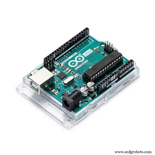
- Arduino Uno
- Capteur infrarouge
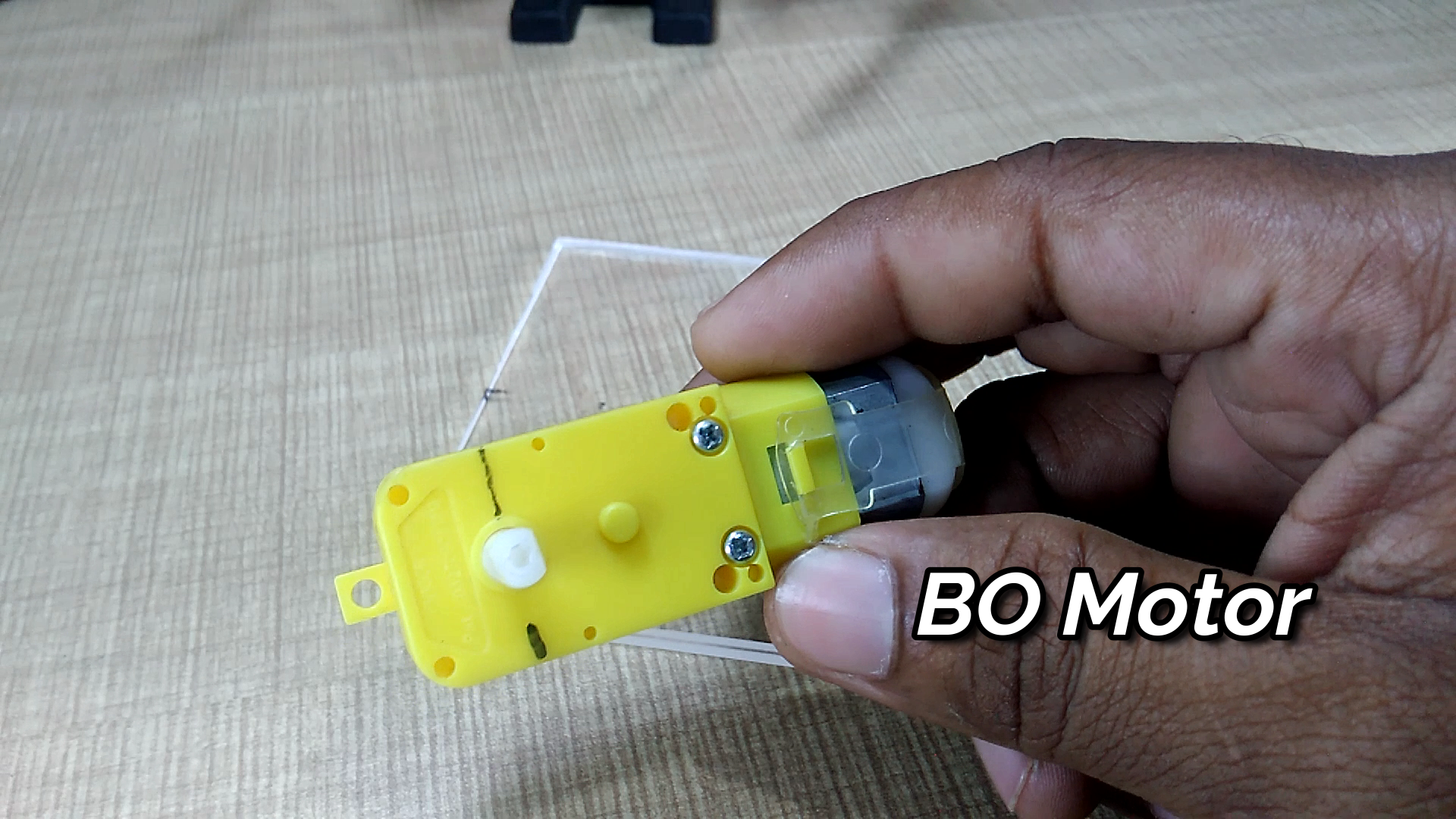
- Moteur BO
- Roues
- Roue pivotante
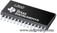
- IC L293d
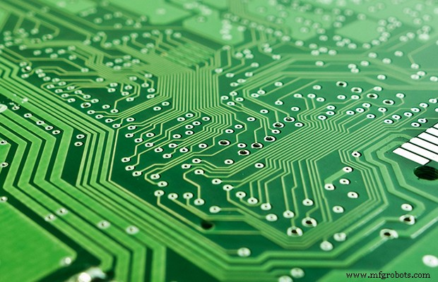
- PCB
- Fil souple
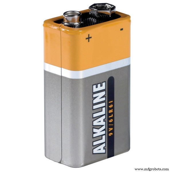
- Batterie
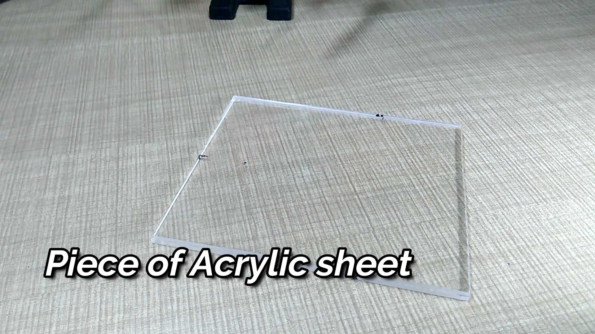
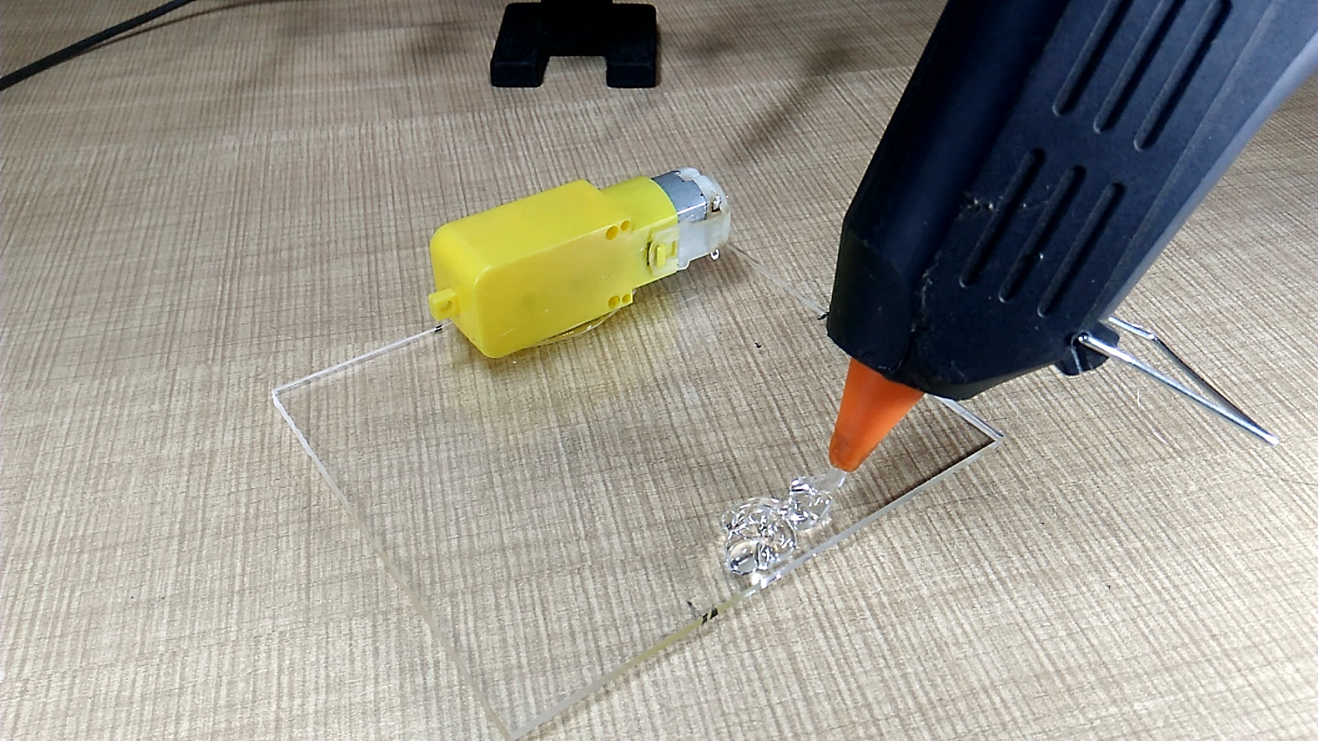
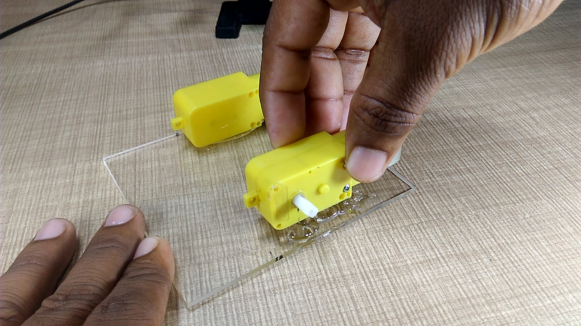
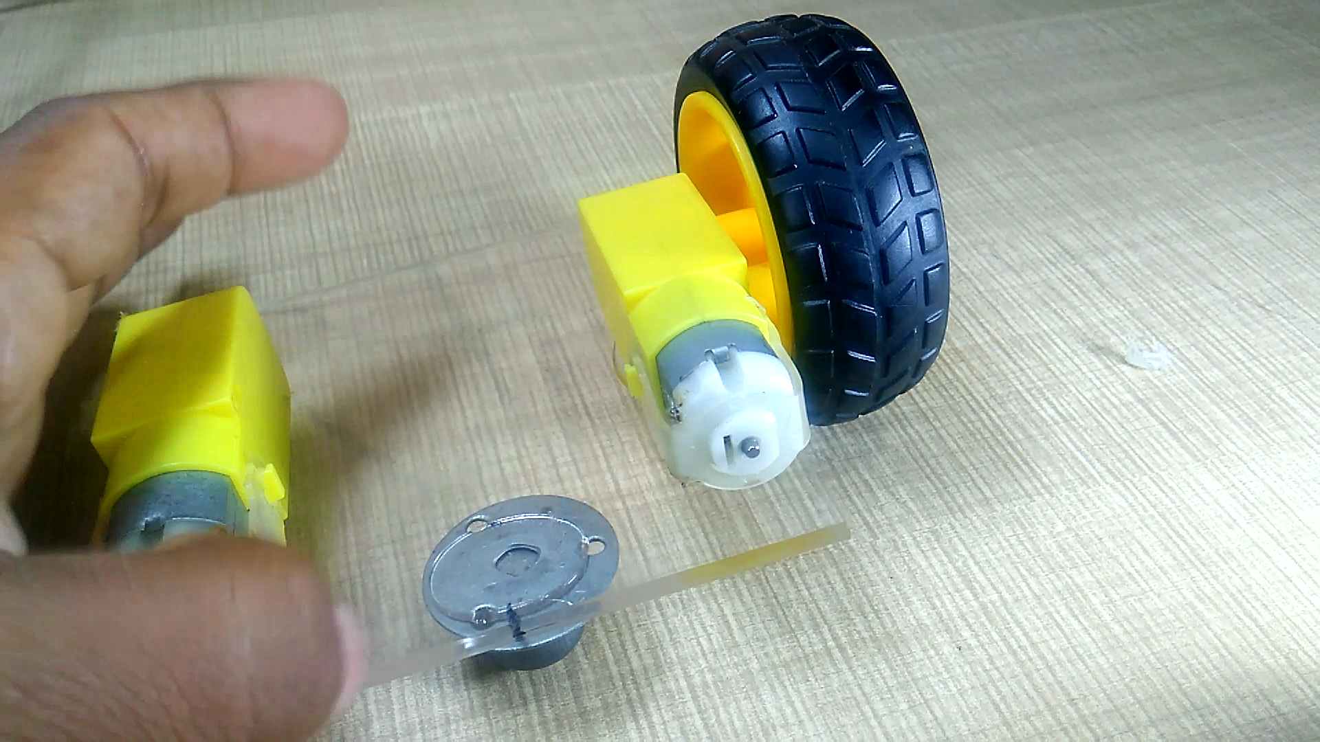
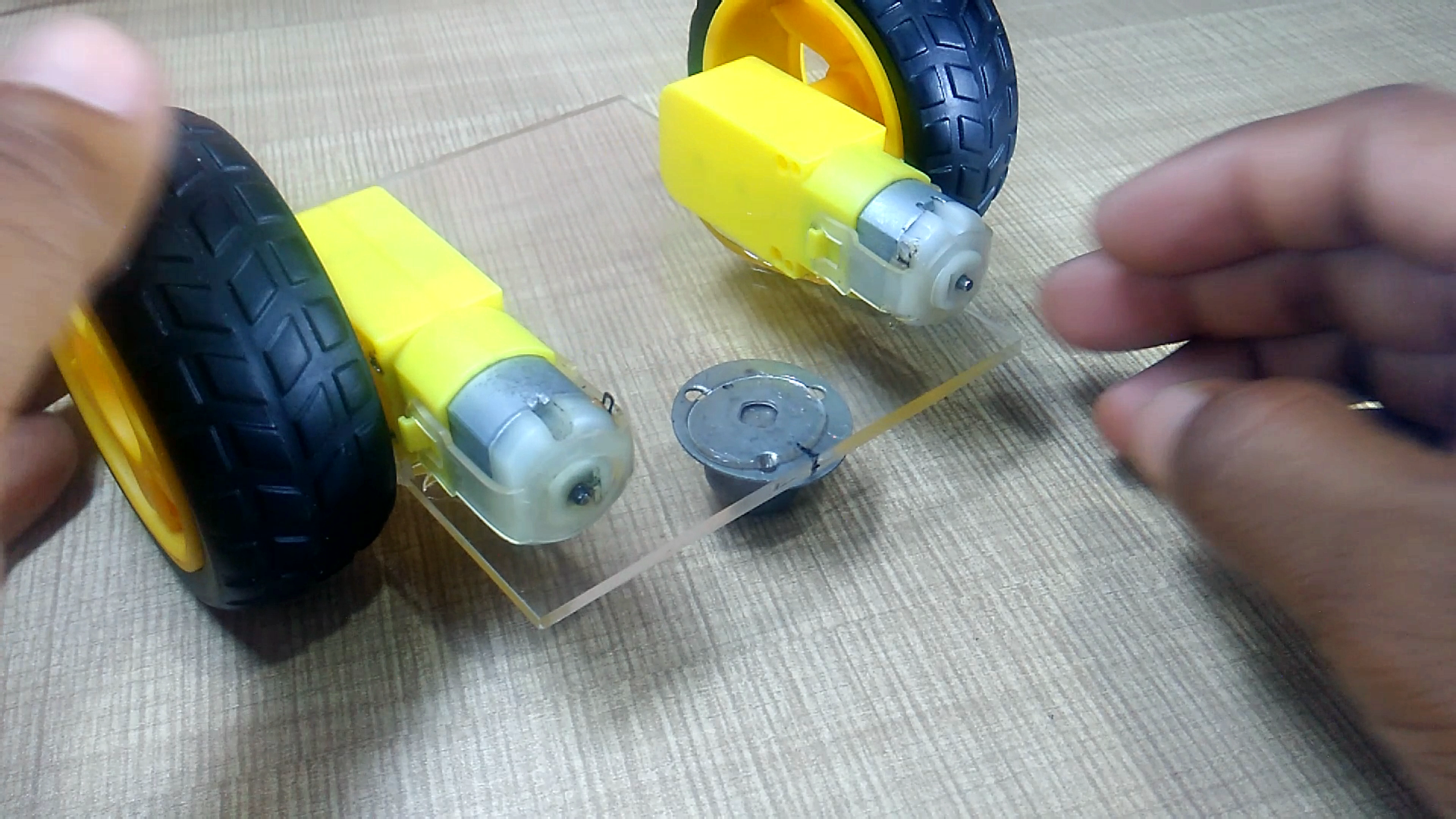
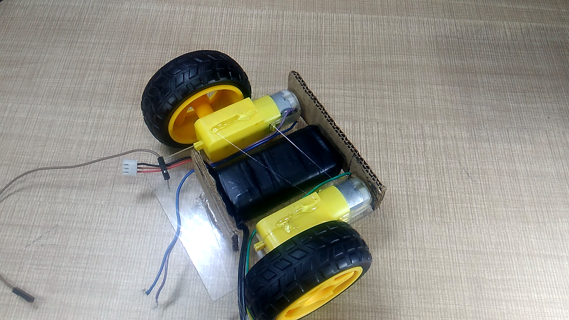
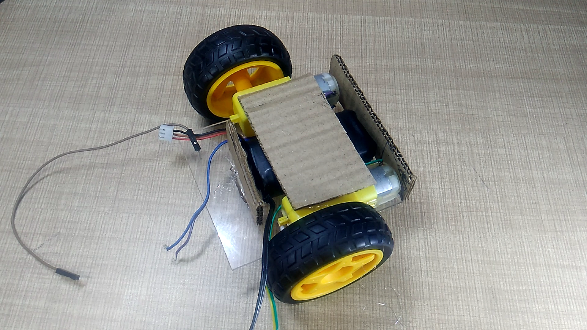
Fixez tous les composants sur une feuille acrylique et faites un châssis comme indiqué sur les images.
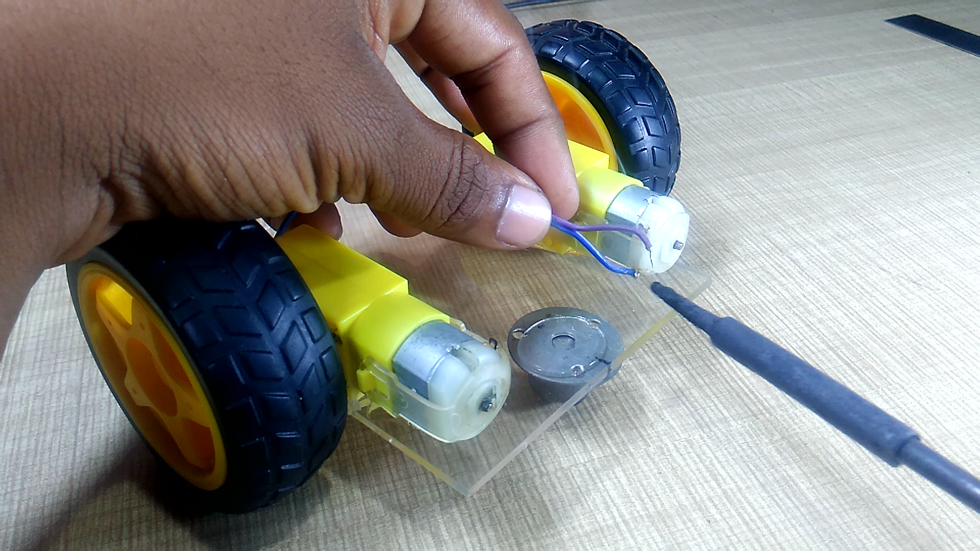
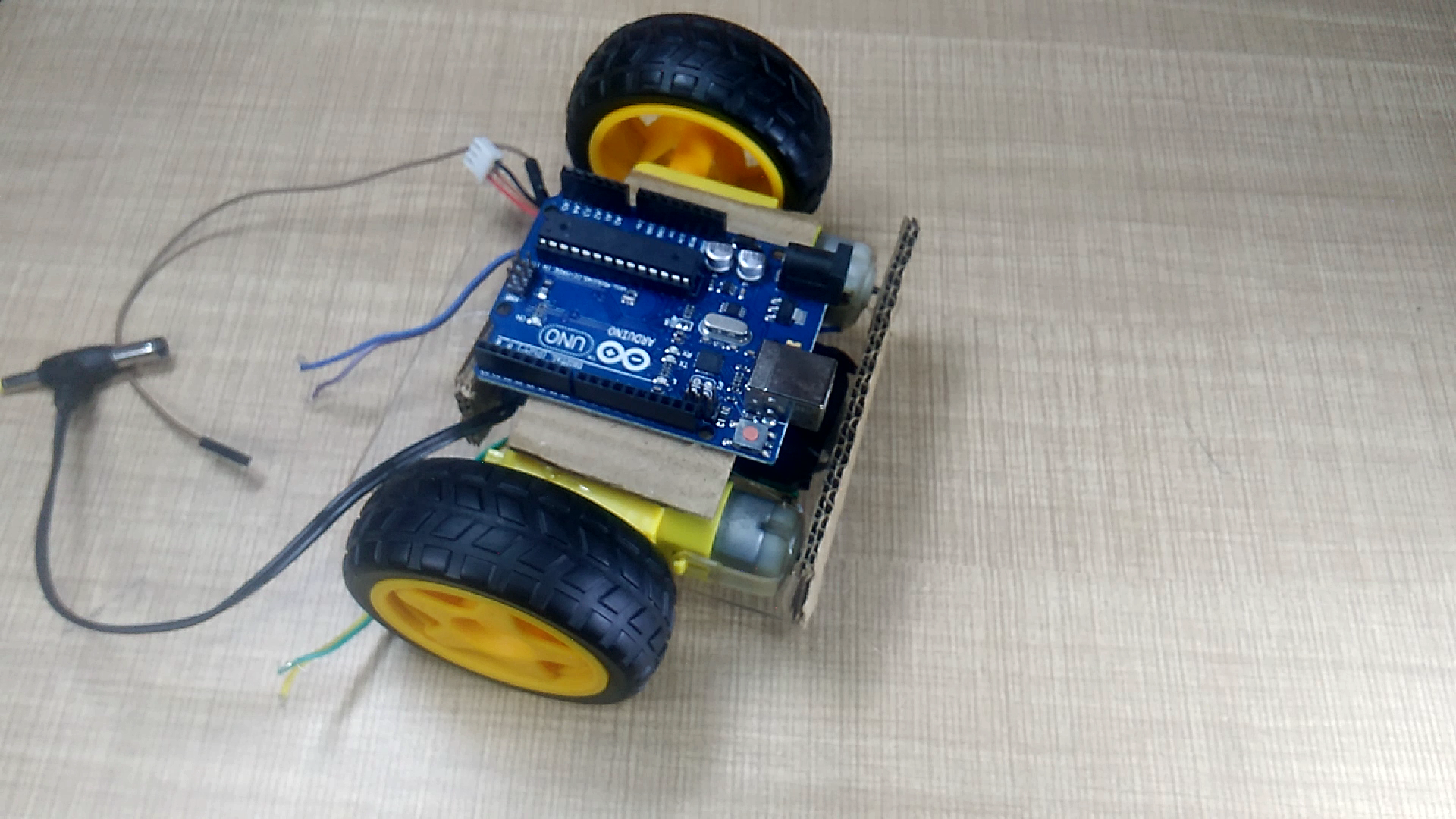

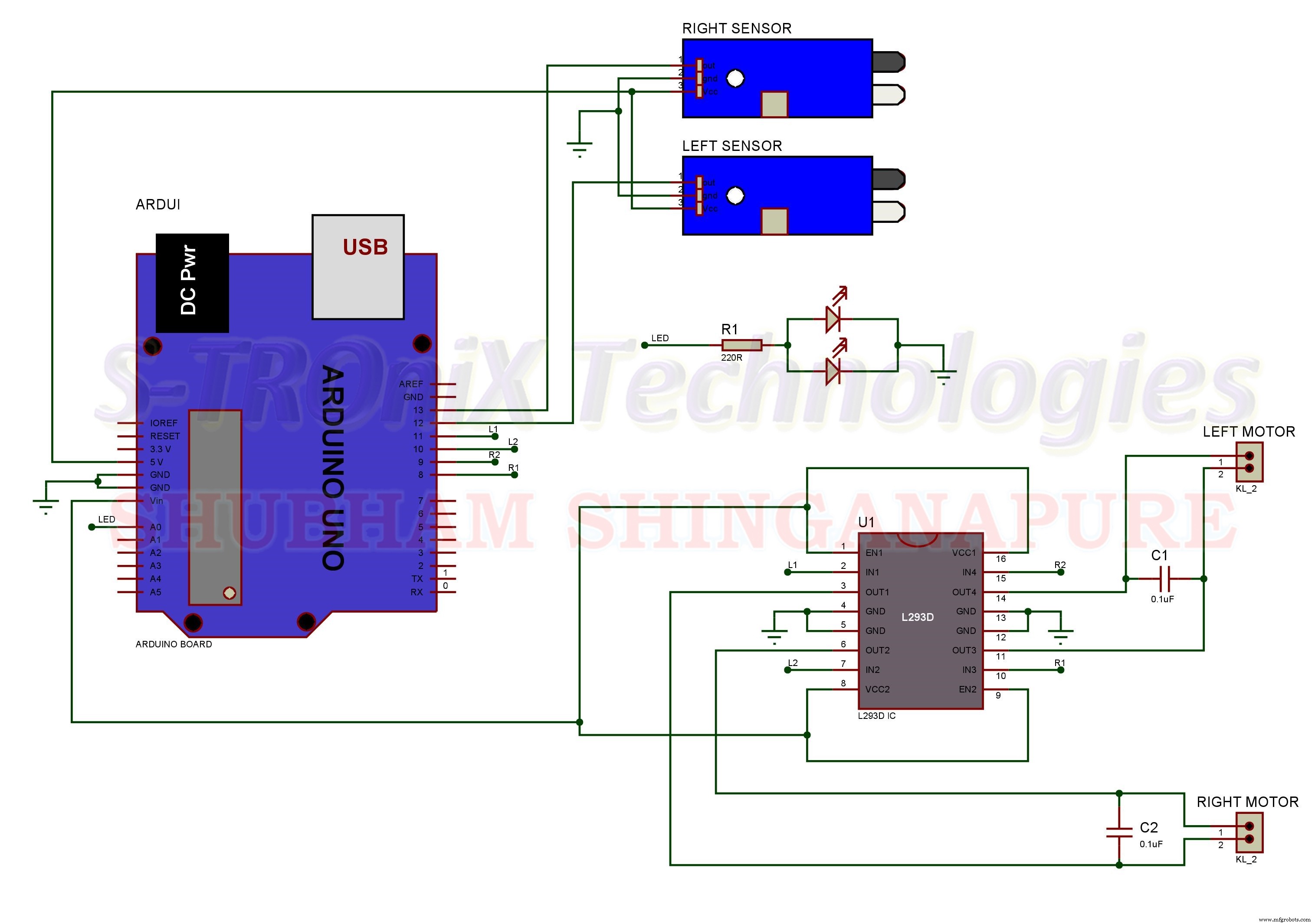
Effectuez maintenant toutes les connexions selon le schéma de circuit ci-dessous.

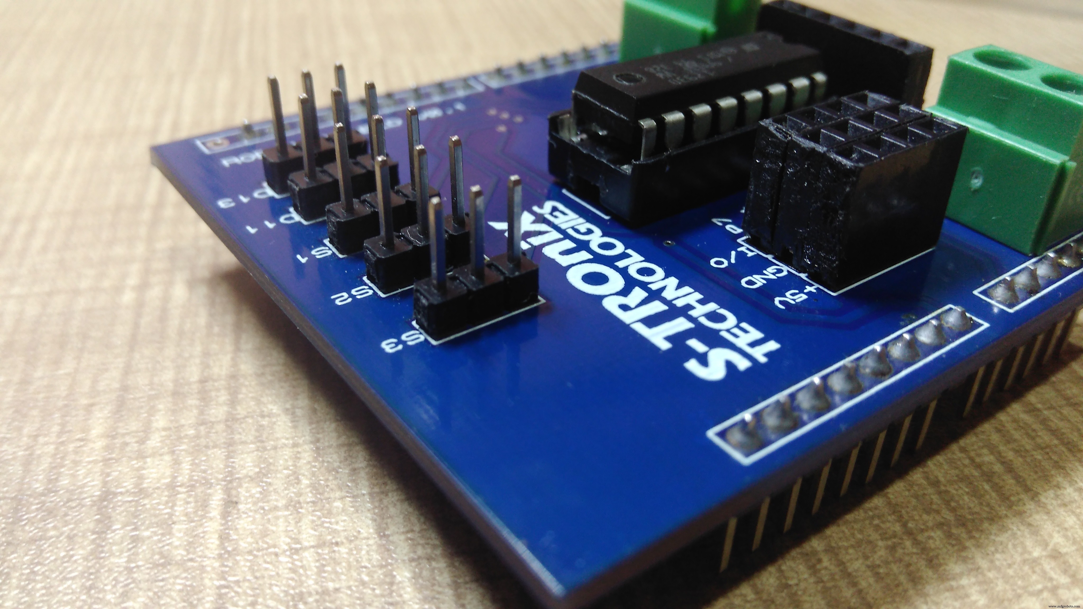
vous pouvez faire ce circuit sur un circuit imprimé en pointillé comme celui-ci.
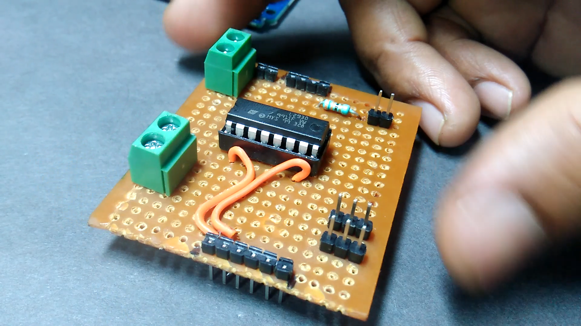
ou peut utiliser ce type de PCB d'aspect professionnel.
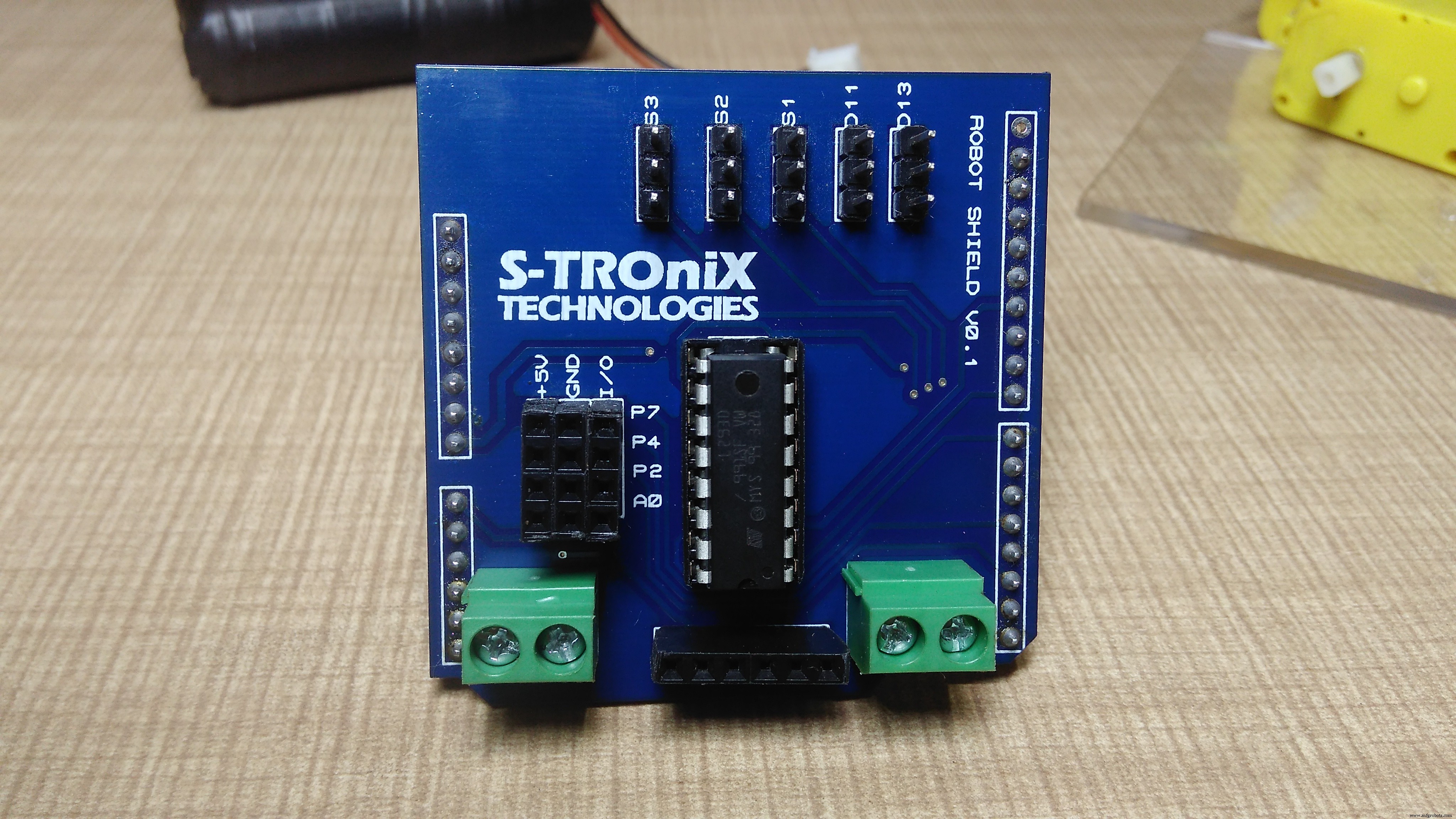
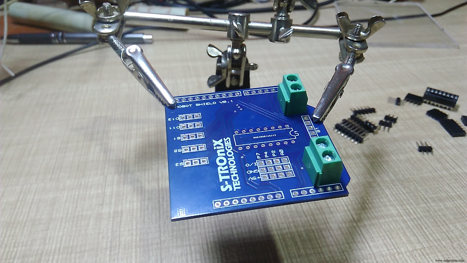
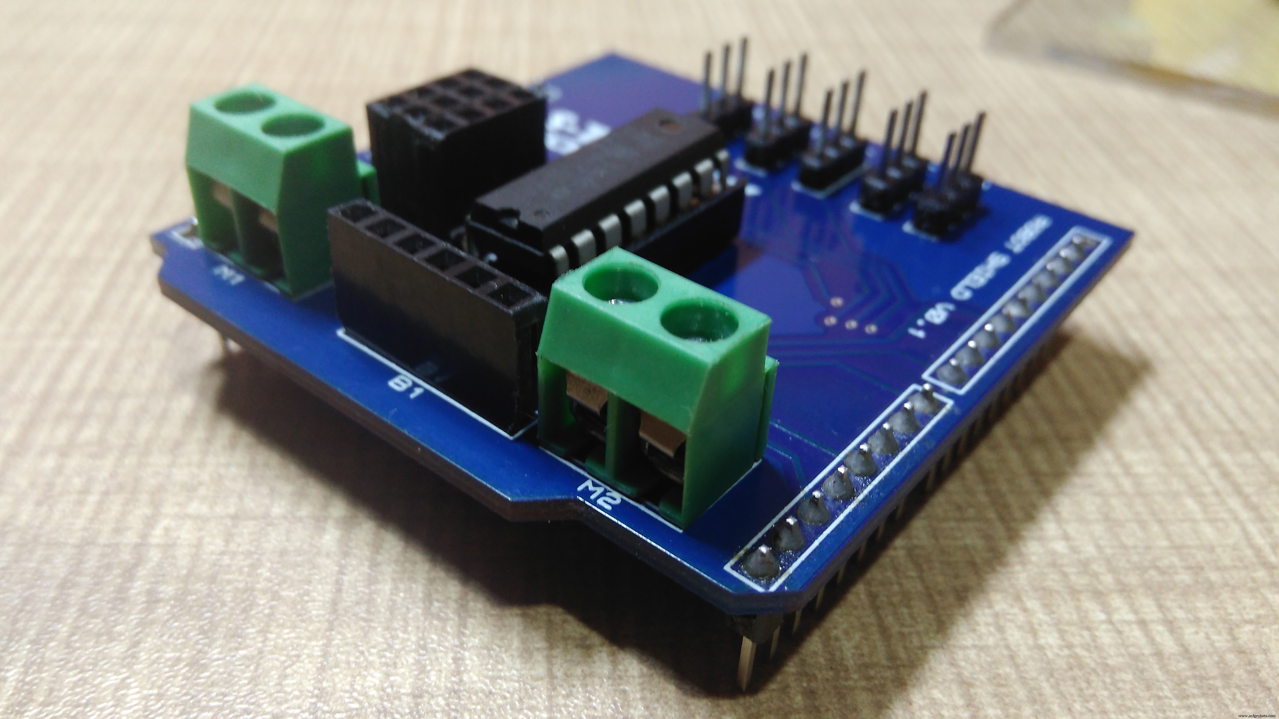
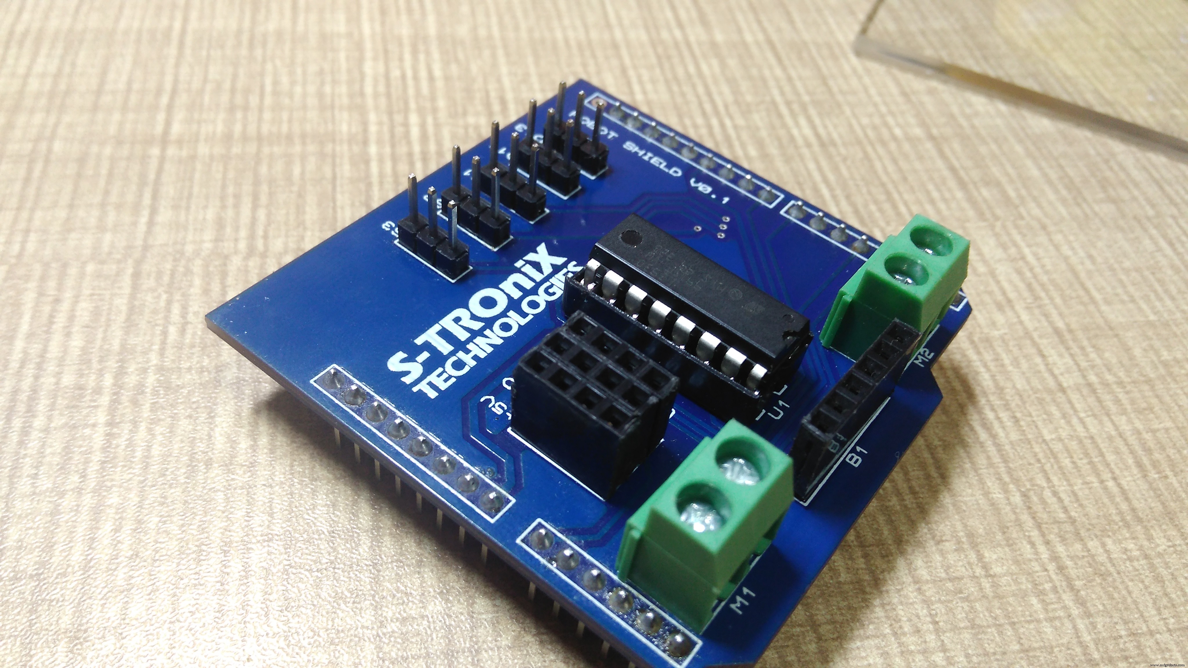
vous pouvez commander des PCB pour ce bouclier ici https://www.pcbway.com/project/shareproject/How_to_Make_Arduino_Based_Edge_Avoiding_Robot.html
ou pour un bouclier prêt à l'emploi, contactez-nous sur :https://www.facebook.com/STROniXTechnologies
Il est maintenant temps de programmer ce robot. téléchargez ce programme sur arduino et tout est fait.
//programme par Shubham Shinganapure le 05-08-2019
//
//pour Line Follow Robot utilisant des capteurs 2IR
int lm1=8 ; //sortie moteur gauche 1
int lm2=9; //sortie moteur gauche 2
int rm1=10; //sortie moteur droit 1
int rm2=11; //sortie moteur droit 2
int sl=13; //entrée capteur 1 (gauche)
int sr=12; //entrée capteur 2 (droite)
int SlV=0;
int SrV=0;
int led=A0;
void setup()
{
 pinMode(lm1,OUTPUT);
 pinMode(lm2,OUTPUT);
 pinMode(rm1,OUTPUT);
 pinMode(rm2,OUTPUT);
 pinMode(led, OUTPUT);
 pinMode(sl,INPUT);
 pinMode(sr,INPUT);
sTOP();
}
boucle vide()
 {
 SlV=digitalRead(sl);
 SrV=digitalRead(sr);
 if(SrV==LOW &&SlV==LOW)
 {
 ForWard( );
 }
 if(SrV==HIGH &&SlV==LOW)
 {
 Gauche();
 }
 if(SrV==LOW &&SlV==HIGH)
 {
 Right();
 }
 if(SrV==HIGH &&SlV==HIGH)
 {
 sTOP();
 }
}
void ForWard()
 {
 digitalWrite(lm1,HIGH);
 digitalWrite(lm2,LOW);
 digitalWrite(rm1,HIGH);
 digitalWrite(rm2,LOW);
 }
 void BackWard()
 {
 digitalWrite(lm1,LOW);
 digitalWrite(lm2,HIGH);
 digitalWrite(rm1,LOW);
 digitalWrite(rm2,HIGH);
 }
 void Left()
 {
 digitalWrit e(lm1,LOW);
 digitalWrite(lm2,HIGH);
 digitalWrite(rm1,HIGH);
 digitalWrite(rm2,LOW);
 }
 void Right()
 {
 digitalWrite(lm1,HIGH);
 digitalWrite(lm2,LOW);
 digitalWrite(rm1,LOW);
 digitalWrite(rm2,HIGH );
 }
 void sTOP()
 {
 digitalWrite(lm1,LOW);
 digitalWrite(lm2,LOW);
digitalWrite(rm1, LOW);
 digitalWrite(rm2,LOW);
 }
Pour en savoir plus abonnez-vous à ma chaîne youtube :
Code
- robot suiveur de ligne
robot suiveur de ligneArduino
Schémas
Processus de fabrication
- Robot Raspberry Pi contrôlé par Bluetooth
- Robot Pi simple
- Obstacles pour éviter le robot avec servomoteur
- Robot Joy (Robô Da Alegria)
- Robot suiveur de ligne de vitesse V4
- Robot à commande vocale
- Robot piano contrôlé par Arduino :PiBot
- Plateforme de formation Arduino
- Robot pour une navigation intérieure super cool