


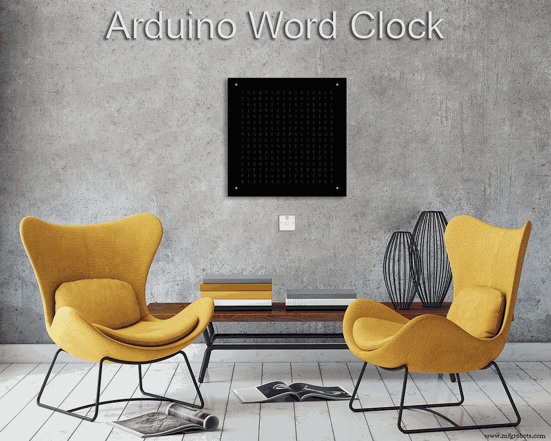
Word Clock avec résolution en minutes du temps en mots
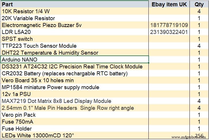
Composants et fournitures
 |
| × | 1 |
À propos de ce projet
Plus de détails sur cette version peuvent être trouvés sur mon site ici :Word Clock
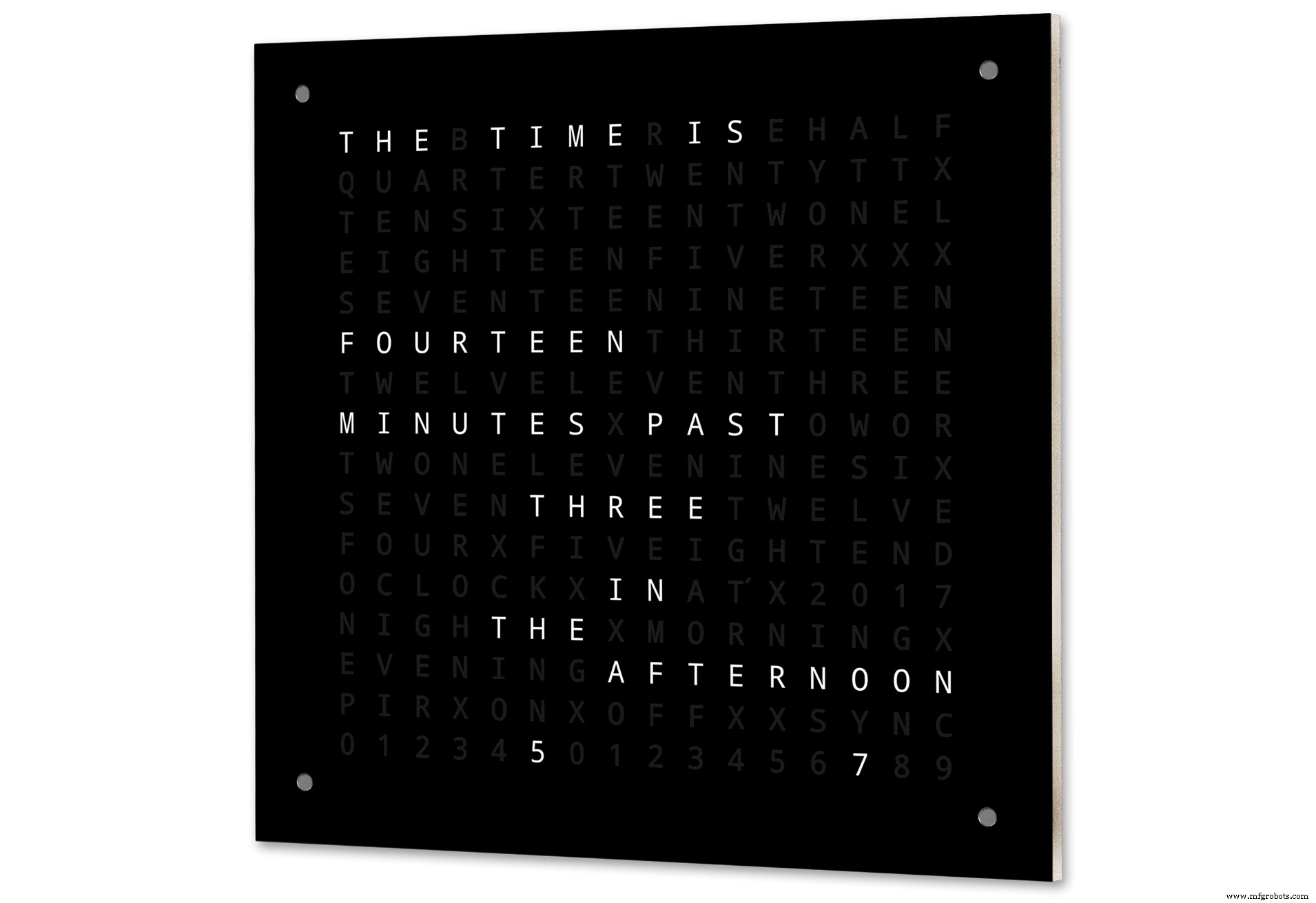
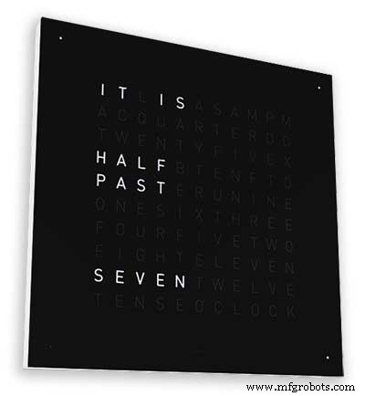
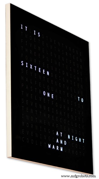
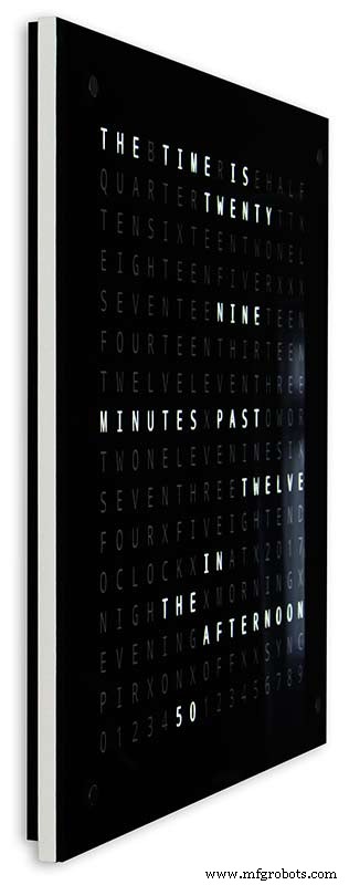
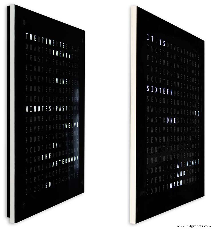
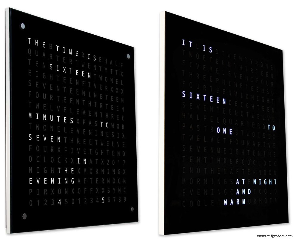
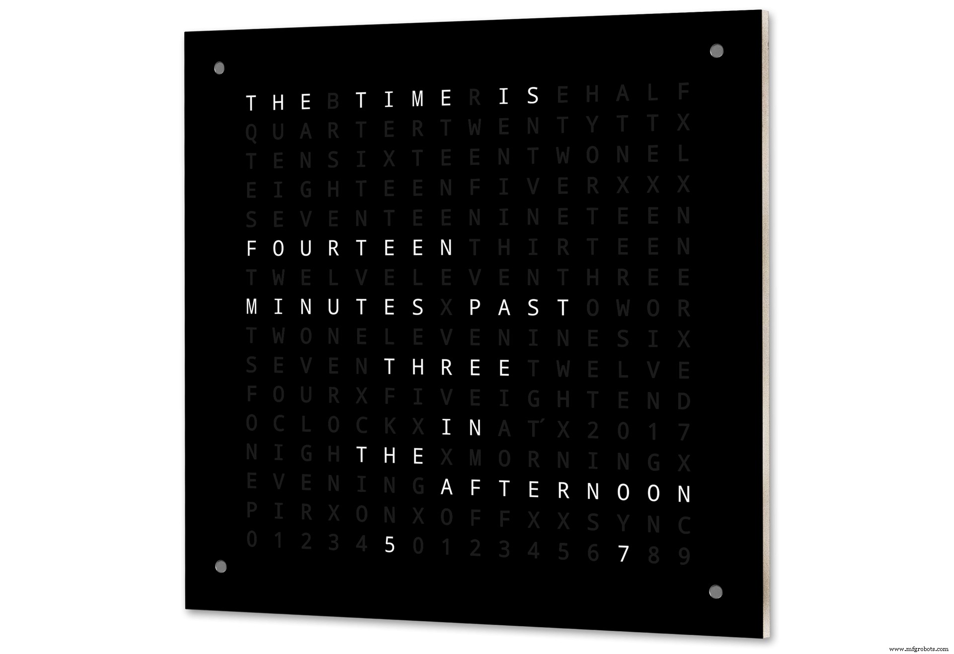
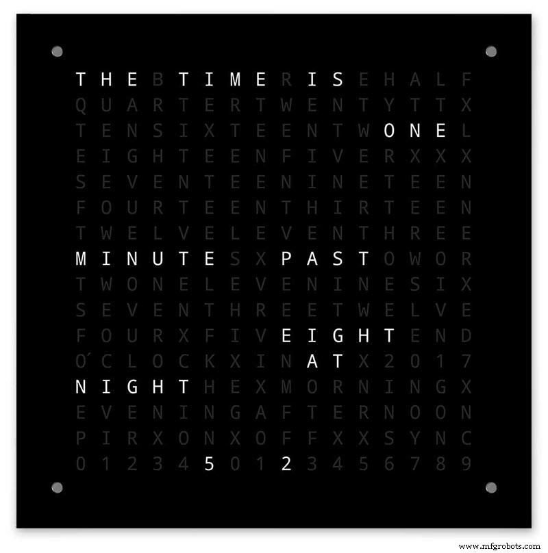
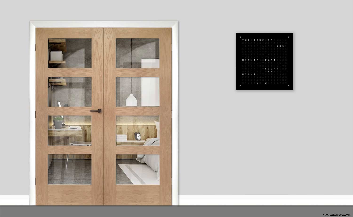
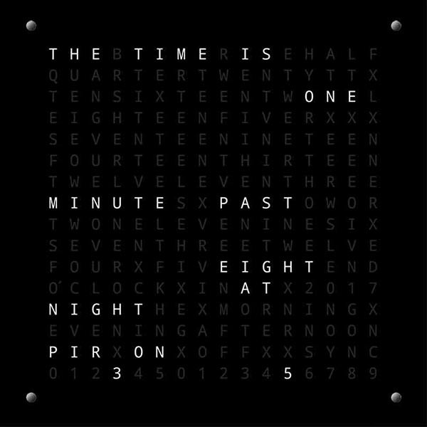
L'horloge de mots Arduino avec résolution en minutes du temps en mots et affichage linéaire des secondes.
Il existe également des modes pour l'horloge numérique, l'horloge analogique, la température et l'humidité, ainsi que trois jeux :Game of Life, Simon et Tetris.
L'horloge peut être autonome ou fonctionner comme esclave d'une horloge maître si nécessaire.
Sans horloge principale, l'heure est contrôlée par l'horloge en temps réel à compensation de température intégrée de l'horloge de mots.
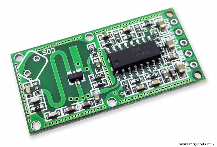
Il existe une option pour le contrôle radar PIR ou Doppler afin que l'horloge s'éteigne automatiquement lorsque personne n'est dans la pièce.
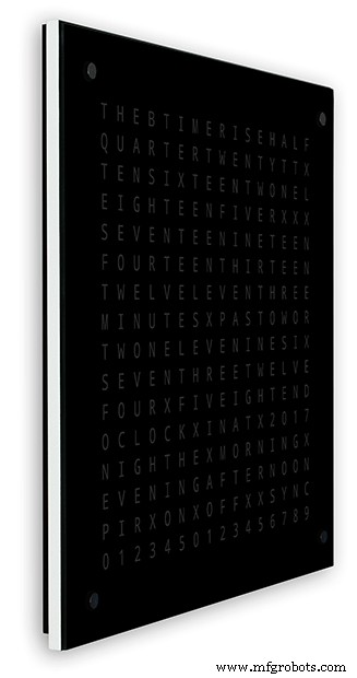
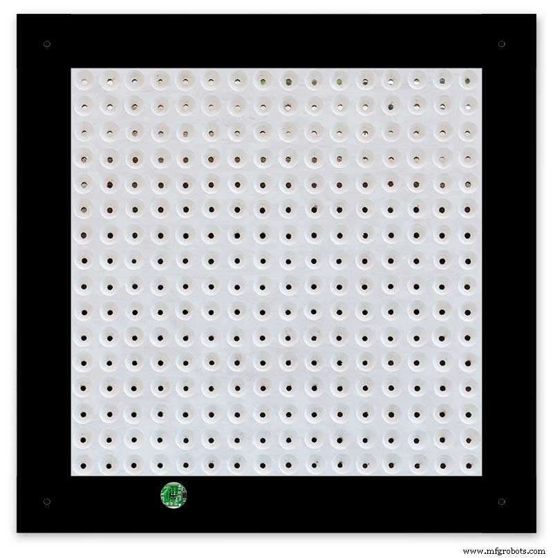
L'horloge mesure 500 mm x 500 mm (19,68 "x19,68"), pèse 12 lb (5,5 kg) et est conçue pour être fixée au mur. Il y a des pavés tactiles dans chaque coin pour configurer et contrôler l'horloge.
Étape 1 :À propos des horloges de mots
À propos des horloges de mots
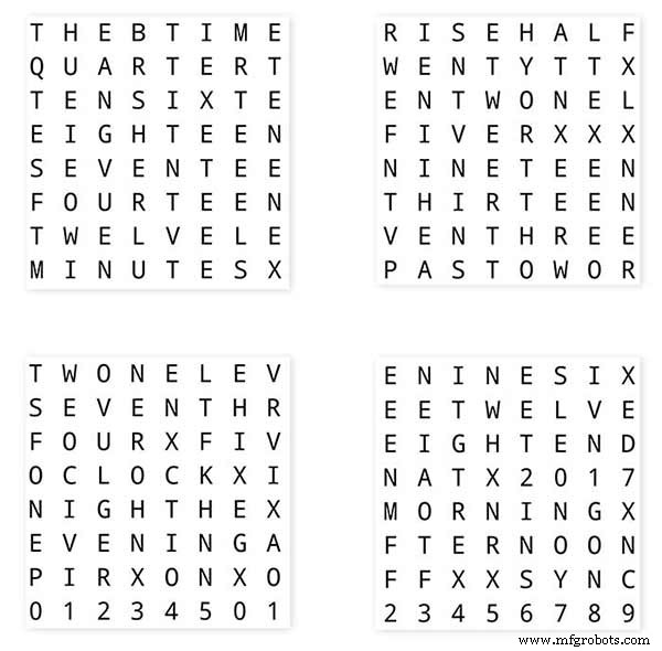
Les horloges à mots indiquent l'heure à l'aide d'une matrice de mots ou de chiffres et de lettres et existent depuis de nombreuses années. Il existe quelques types de conception différents qui affectent la complexité de la construction de l'horloge.
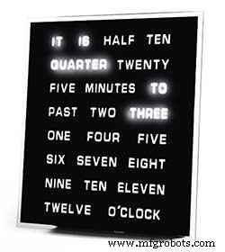
Les plus simples utilisent des blocs de mots pour indiquer l'heure avec une résolution de cinq minutes, par exemple O'CLOCK, 5 PAST, 10 PAST, etc. Ces horloges n'utilisent qu'une vingtaine de blocs LED individuels et sont donc les plus simples à construire. Le principal inconvénient de ces horloges est qu'elles ne peuvent afficher l'heure que dans ce format défini.
L'horloge de niveau moyen a une matrice de LED 11x10 plus quatre LED supplémentaires autour de l'extérieur de l'horloge. L'horloge contrôlée Raspberry Pi Photo 2 a même des LED multicolores et comme elle a 110 LED individuelles, elle peut afficher des chiffres et des images de base. Ces horloges utilisent toujours une résolution de 5 minutes en mots, mais ajoutent souvent "juste passé 5 passé" ou presque 10 " pour augmenter légèrement la résolution. Souvent, les quatre LED autour des coins du cadre indiquent les quatre minutes qui passent pour combler l'écart entre la résolution exprimée en minutes 5. Ces horloges sont raisonnablement complexes à construire et utilisent souvent des bandes de LED pour faciliter la construction.
Il existe des versions commerciales de ce type d'horloge. La version murale de 450 mm coûte environ 1 000 £ et comprend des panneaux avant interchangeables dans de nombreuses couleurs et matériaux, ainsi qu'un bureau et des montres plus petits.
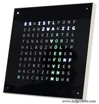
Word Clock 256 matrices par Wouter Devinck
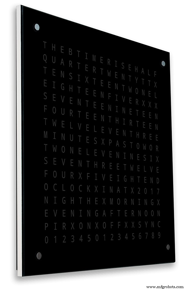
Les horloges de mots avec le plus haut niveau de complexité utilisent une matrice de LED 16x16 donnant 256 LED complètes à contrôler. Ces horloges ont une résolution d'une minute ainsi que le matin, le soir, la nuit, etc. Elles indiquent souvent la température approximative en mots comme chaud, très chaud, froid très froid etc.
Avec les 256 LED avec lesquelles jouer, il existe d'énormes quantités de modes d'affichage différents disponibles. Ces horloges sont assez complexes à construire en raison du nombre de connexions dans l'affichage matriciel. La construction de la matrice LED sur des circuits imprimés avec des composants à montage en surface permet des corps d'horloge très minces et simplifie la construction de l'écran, mais au-dessus de 500 mm x 500 mm, les circuits imprimés commencent à devenir chers.
La construction à la main de la matrice LED comme dans mon horloge a besoin d'espace et 500 mm x 500 mm est un bon point de départ car cela peut à peu près accueillir les grands métiers à tisser nécessaires pour interconnecter les LED et les modules d'affichage. De très grandes horloges murales peuvent être construites à l'aide de matrices LED fabriquées à la main.
Étape 2 : Modifications
Modifications
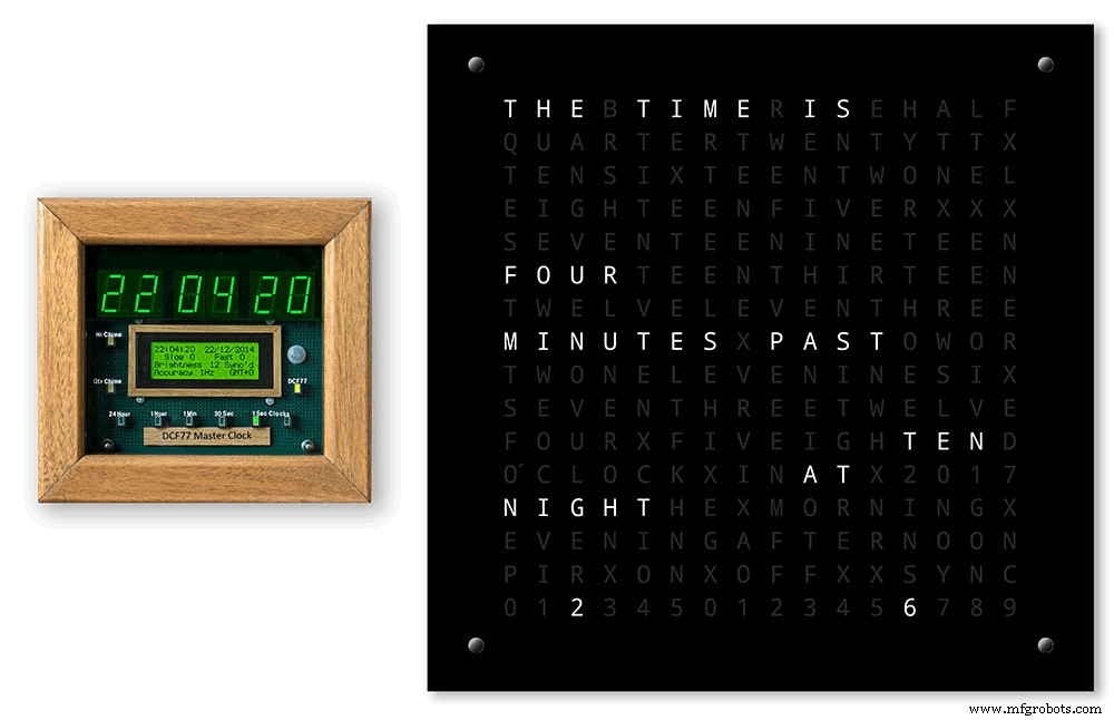
Cette horloge est un mélange du matériel Wouter Devinck Clock et du logiciel d'horloge "catalan" Pijuana. Je n'ai utilisé aucun circuit imprimé, juste des modules prêts à l'emploi et trois petits circuits de carte Vero pour l'alimentation.
Les principaux changements sont détaillés ci-dessous.
Aucun PCB personnalisé n'est utilisé dans cette version de l'horloge, juste bon marché et facile à trouver grâce à des modules préconstruits.
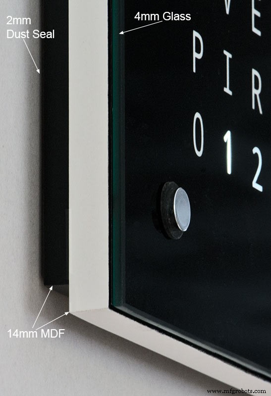
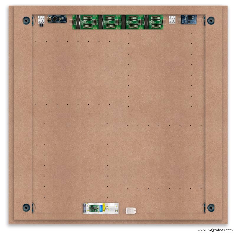
Le corps principal de l'horloge est composé de 2 feuilles de MDF de 14 mm plutôt que d'une seule feuille de 18 mm.
La feuille arrière est 10 mm plus petite que la feuille avant sur tous les côtés sauf le haut, de sorte que l'horloge semble n'avoir que 14 mm d'épaisseur.
L'horloge Wouter Devinck ne mesure que 20 mm de profondeur, y compris le verre de 2 mm, tandis que mon horloge mesure en réalité 34 mm de profondeur, y compris le verre de 4 mm et le joint anti-poussière de 2 mm à l'arrière. En raison du retrait du panneau arrière de 14 mm et du retrait de 1,5 mm du panneau de verre sous la plupart des angles, l'horloge n'a l'air que de 14 mm de profondeur. Cette profondeur supplémentaire m'a permis d'utiliser une matrice LED fabriquée à la main et des métiers à tisser plutôt que 4 gros PCB. Cela signifie également que je peux utiliser des modules préconstruits faciles à entretenir sans circuits intégrés à montage en surface sur les cartes MAX7219.
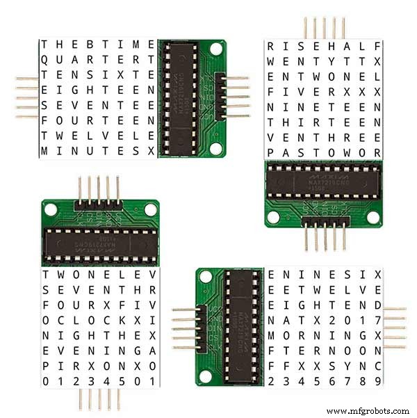
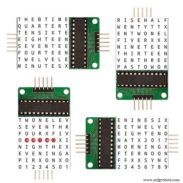
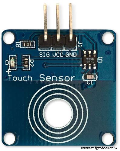
L'affichage principal est construit directement sur les LED d'affichage sans PCB, donc n'importe quelle taille d'affichage est possible. Les modules de capteur tactile TTP223 sont utilisés à la place des Azoteq IQS127D montés sur les cartes principales.
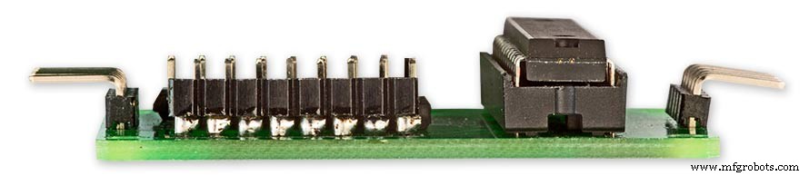
Les cartes pilotes d'affichage pour le MAX7219 I/C utilisent des cartes matricielles LED modifiées. Ces cartes sont livrées complètes avec tous les composants.
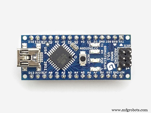
Un Arduino Nano est utilisé pour piloter l'horloge en raison de sa petite taille.
Un module de capteur PIR est utilisé pour éteindre l'écran lorsque personne n'est dans la pièce (cela peut être désactivé pour garder l'écran toujours allumé).
Une résistance de réglage est ajoutée au circuit, accessible depuis le bas de l'horloge avec un petit tournevis plat pour calibrer la luminosité de l'affichage automatique.
Synchronisation avec mon système d'horloge mère toutes les minutes sur 30 secondes. Si aucune impulsion de synchronisation n'est disponible, l'horloge fonctionnera librement en utilisant le RTC. Les impulsions de synchronisation sont affichées sur l'écran principal.
Le logiciel est principalement basé sur la version "catalane" Pijuana de l'horloge de mots, elle a donc été traduite en anglais pour l'affichage. Affichage des crédits modifié à partir de la version "catalane" Pijuana" pour afficher le numéro de version actuelle du logiciel, mon nom et aussi l'année de construction.
La température indiquée a été supprimée de l'affichage de l'horloge et un affichage des secondes linéaires a été ajouté à la rangée inférieure des horloges Word, Digital et Analogique.
Lorsque le PIR est activé ou désactivé, « PIR ON » ou « PIR OFF » s'affiche pendant quelques secondes sur l'affichage de l'horloge de mots.
Cette horloge utilise un module d'horloge en temps réel de précision DS3231 AT24C32 I2C selon l'horloge Wouter Devinck et l'horloge "catalane" Pijuana. Je n'aime pas utiliser la batterie rechargeable Lithium-Ion fournie avec le module. J'utilise une batterie non rechargeable et j'ai modifié le module en conséquence.
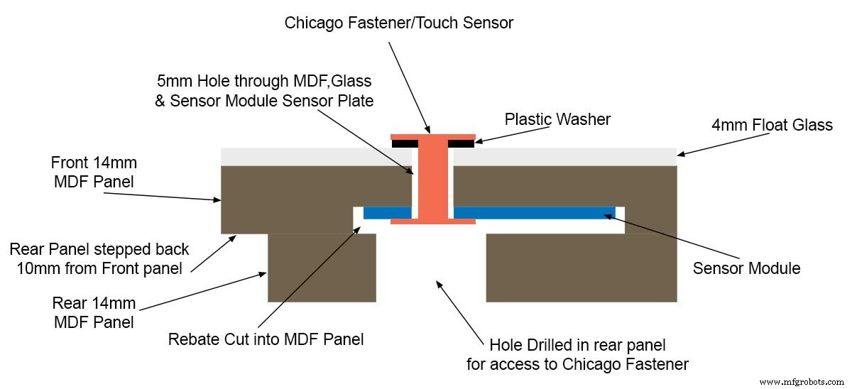
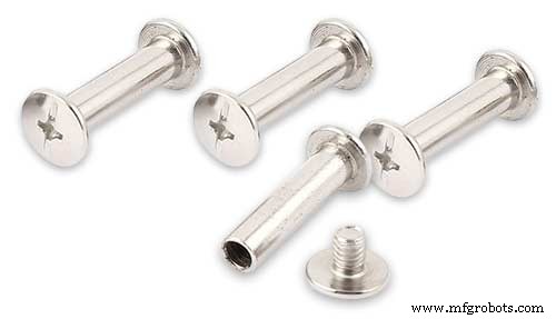
Le verre float de 4 mm avec bords polis remplace le verre de 2 mm. Le verre est fixé au panneau MDF principal à l'aide de Chicago Fasteners plutôt que de colle. Ceux-ci agissent également comme des pavés tactiles pour contrôler l'horloge et permettent de retirer le verre si nécessaire.
Deux joints anti-poussière sont intégrés à l'horloge, un sur le panneau arrière et un derrière le panneau d'affichage en verre amovible. En mode de réglage de l'horloge, appuyer sur le bouton droit BOT remet maintenant les secondes à 0.
Les modifications suivantes au libellé anglais ont été apportées pour rendre le libellé tel que je le dirais. La façon dont les individus disent que l'heure varie d'une région à l'autre en fonction de l'endroit où vous vivez/allez à l'école, etc.
Suppression des mots indiquant la température sur l'horloge de mots. Ceux-ci ont été remplacés par l'état de synchronisation, le PIR ON/OFF et l'affichage linéaire des secondes.
Changement de "MINUTES" en "MINUTE" à 1 minute après et 1 minute à l'heure.
Ajout d'un "A" avant le passé "TRIMESTRE" et "TRIMESTRE" à l'heure.
Ajout du "ELEVEN" manquant de l'horloge de Wouter Devinck selon ses notes.
A midi changé l'heure pour lire DOUZE HEURES DANS L'APRÈS-MIDI.
At Midnight a changé l'heure pour lire DOUZE HEURES LA NUIT. Après minuit, l'horloge indiquera toujours LE MATIN.
Le "O'CLOCK" n'est plus ponctué et affiche simplement OCLOCK.
Étape 3 :Conception du boîtier
Comme mon horloge n'utilise pas de circuits imprimés à matrice d'affichage personnalisés avec des composants à montage en surface, mon boîtier d'horloge doit être un peu plus profond que la conception de Wouter.
Mon boîtier a une profondeur de 34 mm et comprend le joint anti-poussière arrière de 2 mm, le panneau MDF arrière de 14 mm, le panneau d'affichage avant de 14 mm et le verre flotté de 4 mm.
Le boîtier de Wouter à droite n'a que 21 mm de profondeur, un seul panneau MDF de 18 mm et un verre flotté de 2 mm.
Afin de rendre mon horloge moins encombrante à l'œil lorsqu'elle est montée au mur, j'ai incorporé quelques caractéristiques de conception simples. La photo ci-dessus montre mon horloge à gauche et l'horloge de Wouter à droite. D'un angle de vue latéral extrême, vous pouvez clairement voir que mon boîtier a l'air plus volumineux.
Ceci est quelque peu compensé par le fait que le panneau arrière est noir plutôt que blanc, ce qui fait que votre œil se concentre sur le bord mince et blanc de 14 mm. La planche arrière étant 10 mm plus courte en bas et les deux côtés renforcent cette illusion.
Ci-dessus - encore mon horloge à gauche et l'horloge de Wouter à droite. Plus vous vous dirigez vers l'avant des horloges, plus le panneau arrière plus court de mon horloge disparaît de la vue jusqu'à ce que seul le panneau avant mince de 14 mm soit visible. Le verre de 4 mm est également coupé de 1 à 2 mm plus court que le panneau avant, ce qui aide à le cacher. . Mon boîtier volumineux de 34 mm semble maintenant aussi mince que le boîtier de Wouter.
Étape 4 : contrôles
Contrôles

Il y a des modules de commande tactile TTP223 sur l'horloge, en haut à gauche, en haut à droite, en bas à gauche et en bas à droite de l'écran.
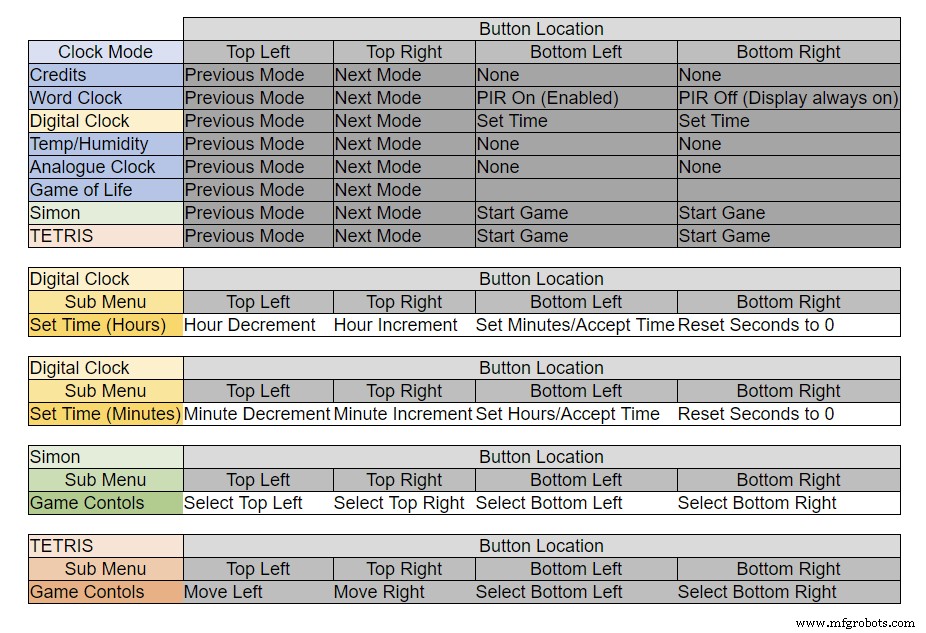
Les boutons ont des fonctions différentes selon le mode dans lequel se trouve l'horloge, voir le tableau ci-dessus.
Étape 5 :Réglage automatique été/hiver
Non utilisé.
Étape 6 :Modes d'affichage Horloges et environnement
L'animation 1 ci-dessus montre les 4 modes d'horloge et d'environnement.
Les modes sont dans l'ordre word clock, horloge numérique, température et humidité, et horloge analogique.
Animation 2 ci-dessus. Il existe également un mode de démarrage qui fait défiler le numéro de version du logiciel, le nom du fabricant et le nom de l'horloge.
Étape 7 : jeux de modes d'affichage
Trois jeux classiques sont codés dans l'horloge. J'ai laissé le code tel quel de l'horloge catalane.

Animation 1 au-dessus de Game of Life de Conway. L'univers du Jeu de la Vie est une grille orthogonale bidimensionnelle infinie de cellules carrées, dont chacune est dans l'un des deux états possibles, vivant ou mort, ou "peuplé" ou "non peuplé".
Chaque cellule interagit avec ses huit voisines, qui sont les cellules adjacentes horizontalement, verticalement ou diagonalement. À chaque étape dans le temps, les transitions suivantes se produisent :Toute cellule vivante avec moins de deux voisins vivants meurt, comme si elle était causée par une sous-population. Toute cellule vivante avec deux ou trois voisins vivants vit jusqu'à la génération suivante. Toute cellule vivante avec plus de trois voisins vivants meurt, comme par surpopulation. Toute cellule morte avec exactement trois voisins vivants devient une cellule vivante, comme par reproduction.
Le motif initial constitue la graine du système. La première génération est créée en appliquant simultanément les règles ci-dessus à chaque cellule de la graine, les naissances et les décès se produisent simultanément, et le moment discret auquel cela se produit est parfois appelé un tick (en d'autres termes, chaque génération est une pure fonction de la précédente. un). Les règles continuent d'être appliquées à plusieurs reprises pour créer d'autres générations.
Animation 2 au dessus de Simon
Jeu de mémoire Simon - essayez et copiez la séquence générée par ordinateur. Lorsque vous entrez votre séquence, appuyez deux fois sur la dernière entrée pour terminer votre tour.
Lorsque vous échouez, votre score s'affiche à l'écran.
Animation 3 ci-dessus TetrisTetris est le jeu vidéo soviétique de puzzle d'association de tuiles sorti en juin 1984. Ce jeu nécessite encore un peu de travail sur les boutons pour contrôler correctement les tuiles.
Étape 8 :Prototypage
L'horloge peut être prototypée et testée à l'aide des LED matricielles DOT d'origine sur les cartes d'affichage MAX7219.
Notez que cette modification temporaire n'est requise que si vous souhaitez tester votre code sur les écrans matriciels DOT fournis avec les modules MAX7219.
Cela signifie que vous pouvez essayer vos modifications de mise en page du logiciel/mot en miniature avant de vous engager dans la version complète. Le câblage de la LED DOT Matrix devra être modifié pour correspondre aux connexions logicielles.
La photo ci-dessus montre comment le module est câblé avant modification. La modification est assez simple. Tout d'abord, pliez les broches de la matrice LED suivantes à 90°, les broches supérieures vers le haut et les broches inférieures vers le bas.
Broches 16, 15, 3, 4, 10 et 11.
Insérez la matrice LED dans la prise sur le PCB de l'affichage, les broches ci-dessus ne seront plus connectées. Soudez les fils de liaison suivants de l'arrière de la prise du PCB d'affichage aux broches de la matrice LED qui dépassent.
LEDA vers Dot Matrix Pin 16
LEDB vers Dot Matrix Pin 15
LEDG vers la broche matricielle 3
LEDF vers Dot Matrix Pin 4
LEDE à Dot Matrix Pin 10
LEDC vers la broche matricielle 11
J'ai utilisé un multimètre et fait bourdonner le module d'affichage. Le tableau montre où le numéro de broche du logiciel diffère des numéros de broche LED sur la carte d'affichage.
Pour tester vos mises en page de mots, imprimez une version miniature de votre affichage de mots 62 mm x 62 mm sur du papier blanc ordinaire.
Notez l'orientation des panneaux d'affichage LED pour correspondre à la disposition du logiciel.
J'ai conservé la rotation de l'affichage comme l'horloge Wouter Devinck d'origine au cas où quelqu'un utiliserait la conception de circuits imprimés Wouter Devinck pour mon horloge.
Le petit bouton poussoir sous le capteur de température/humidité permet de tester la synchronisation de 30 secondes. Les modules de boutons tactiles se trouvent en bas à gauche de la planche à pain, montés latéralement. Il n'y a pas beaucoup de fils sur ce prototype car la plupart des fils se trouvent dans les matrices d'affichage. Sur l'horloge finale, ce câblage sera fait à la main pour les LED individuelles.
J'ai essayé de nombreuses conceptions word/clock différentes sur cette carte avant d'essayer de construire l'horloge finale.
Étape 9 :Tester les modules modifiés
J'ai modifié le sketch word clock pour permettre au module MAX2719 d'être testé après le câblage mod.
Tout ce programme allume chaque LED à tour de rôle du haut à gauche vers le bas à droite de la matrice.
Connectez simplement 5 fils au module NANO et MAX2719 et alimentez le NANO à partir de son port USB. Chargez le croquis et laissez-le s'exécuter.
Branchez simplement chaque module à tour de rôle pour vérifier votre câblage.
Téléchargez le croquis de test à partir du fichier zip ci-joint.
MAX7219_LED_Test.zip
Étape 10 : temps de mappage de mots
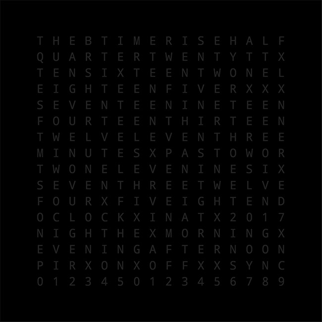
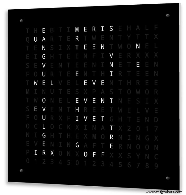
Le tableau ci-dessus montre les correspondances entre le temps et les mots.
Il n'y a pas de règles strictes sur ces derniers, il suffit de définir les mots comme vous diriez l'heure.
Dans mon horloge, j'ai changé ce qui suit par rapport aux mots sur l'horloge de Wouter.
« MINUTES » a été remplacé par « MINUTE » à 1 minute et 1 minute à l'heure. Ajout d'un « A » avant le passé « QUARTER » et « QUARTER » à l'heure.
A midi changé l'heure pour lire DOUZE HEURES DANS L'APRÈS-MIDI.
At Midnight a changé l'heure pour lire DOUZE HEURES LA NUIT.
Après minuit, l'horloge indiquera toujours LE MATIN.
Ces changements sont très faciles à mettre en œuvre dans le logiciel d'horloge.
Word%2Bto%2BTime%2BTranslations.xlsx
Étape 11 :Alimentation
J'utilise un bloc d'alimentation 12 volts commun pour piloter de nombreux types de circuits différents dans ma maison. Cette alimentation 12 volts est ensuite abaissée localement sur chaque circuit avec un module 5 volts pour alimenter la carte de contrôle et divers modules.
Mon alimentation commune a 18 circuits 12v à fusibles individuels, chacun avec un fusible 2A. 9 d'entre eux sont sauvegardés par batterie. Les cartes d'horloge ont également leur propre fusible embarqué.
Si vous utilisez uniquement ce circuit, n'importe quelle alimentation régulée de 5 volts fera l'affaire tant qu'elle peut fournir le courant pour l'utilisation de votre circuit.
J'ai conçu une carte d'alimentation sur Vero qui utilise une alimentation miniature MP1584. Cela convertit la sortie 12v de mon alimentation commune en 5v pour l'horloge.
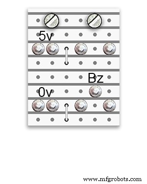
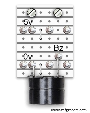
Il y a deux cartes d'alimentation supplémentaires construites à partir de la carte Vero.
En plus de 1 tenant le buzzer, ils ajoutent simplement des points de distribution d'alimentation supplémentaires pour le câblage d'alimentation de l'horloge.
Puissance requise
J'ai mesuré la consommation de courant de l'horloge et à faible luminosité, elle utilise 30 mA et une luminosité maximale de 250 mA. Cela variera bien sûr en fonction du nombre de LED allumées. Par une belle journée ensoleillée, les niveaux de luminosité indiqués sur la sortie série sont de 10. Cela représente environ les 2 tiers de la puissance maximale des LED. La consommation d'énergie globale peut être considérablement réduite si le PIR est allumé. Cela effacera l'affichage si le mouvement n'est pas détecté par l'horloge.
J'utiliserais une alimentation minimale de 500 mA pour alimenter l'horloge. La puissance dépendra grandement du type de LED que vous utilisez.
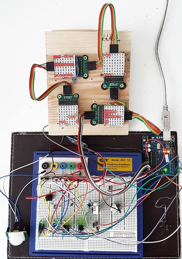
Étape 12 :Interconnexions de modules
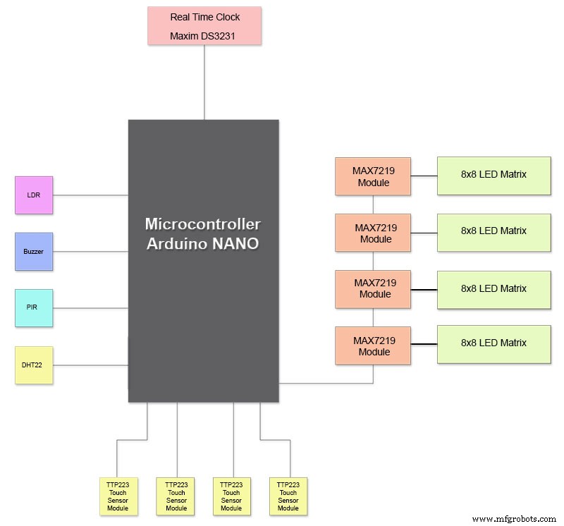
La photo ci-dessus montre comment les modules sont connectés. La plupart des modules se connectent directement à l'Arduino Nano.
Les cartes MAX7219 ne se connectent au NANO que via le module 01. Les autres modules sont connectés en guirlande.
Chaque matrice de 8x8 LED est ensuite connectée à un module MAX7219.
La majeure partie du câblage est constituée des connexions entre les modules MAX7219 et les matrices LED.
Gardez la distance entre le NANO et le 1er module MAX7219 et le module MAX7219 aux modules aussi courte que possible. Assurez-vous également d'alimenter les deux extrémités des MAX7219 en guirlande, car la majeure partie de l'alimentation est tirée par cette partie du circuit.
Étape 13 :Ordre de construction de la construction
Ordre de construction en supposant que tous les changements de prototypage et de logiciel sont terminés en premier.
Obtenez un transfert de vinyle imprimé.
Faites couper du verre.
Découpez des feuilles de MDF recto et verso.
Découpez des trous dans la feuille avant pour les LED.
Peignez les feuilles de MDF.
Percez des trous pour les capteurs dans le verre.
Collez le transfert de vinyle à l'arrière du verre.
Découpez des trous de capteur dans le panneau avant en MDF.
Coupez les remises du module de capteur dans le panneau avant.
Coupez le panneau arrière en MDF et faites 4 trous d'accès pour l'accès au capteur.
Ajoutez des bandes de chant en mélamine aux panneaux MDF, du blanc au panneau avant et du noir au panneau arrière.
Vissez le panneau MDF au panneau MDF avant.
Fabriquez des cartes Vero, 1 carte d'alimentation et 2 cartes de distribution d'alimentation.
Modifiez 4 cartes MAX7219 et ajoutez le câblage aux LED.
Connectez-vous à l'extrémité MAX7219 uniquement pour l'instant.
Montez tous les modules et les cartes Vero à l'arrière de la carte avant en MDF.
Construisez les 4 matrices LED sur la carte MDF avant et soudez 256 LED.
Câblez tous les câbles Batt et Terre à partir de la carte Vero d'alimentation et des cartes de distribution électrique.
Connectez toutes les alimentations à tous les modules.
Connectez tout le câblage aux modules Nano, MAX7219, RTC, capteur de température, capteurs tactiles et buzzer.
Connectez tous les faisceaux de câblage des cartes MAX7219 modifiées aux matrices LED selon le tableau de câblage.
Connectez un module PIR à distance de l'horloge et connectez la connexion PIR.
Connectez la synchronisation de 30 secondes à votre horloge principale (si nécessaire).
Montez le panneau d'affichage avant en verre à l'aide des boulons Chicago fixant également les capteurs tactiles en même temps.
Testez.
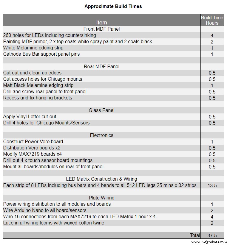
Le tableau 1 montre les temps de construction très approximatifs de cette horloge et variera en fonction de votre niveau de compétence et également des outils spécialisés/espace de travail dont vous disposez.
Vous pouvez facilement ajouter 40 heures supplémentaires de prototypage et de programmation à cette liste.
Étape 14 : Autocollant en vinyle de construction
Autocollant en vinyle
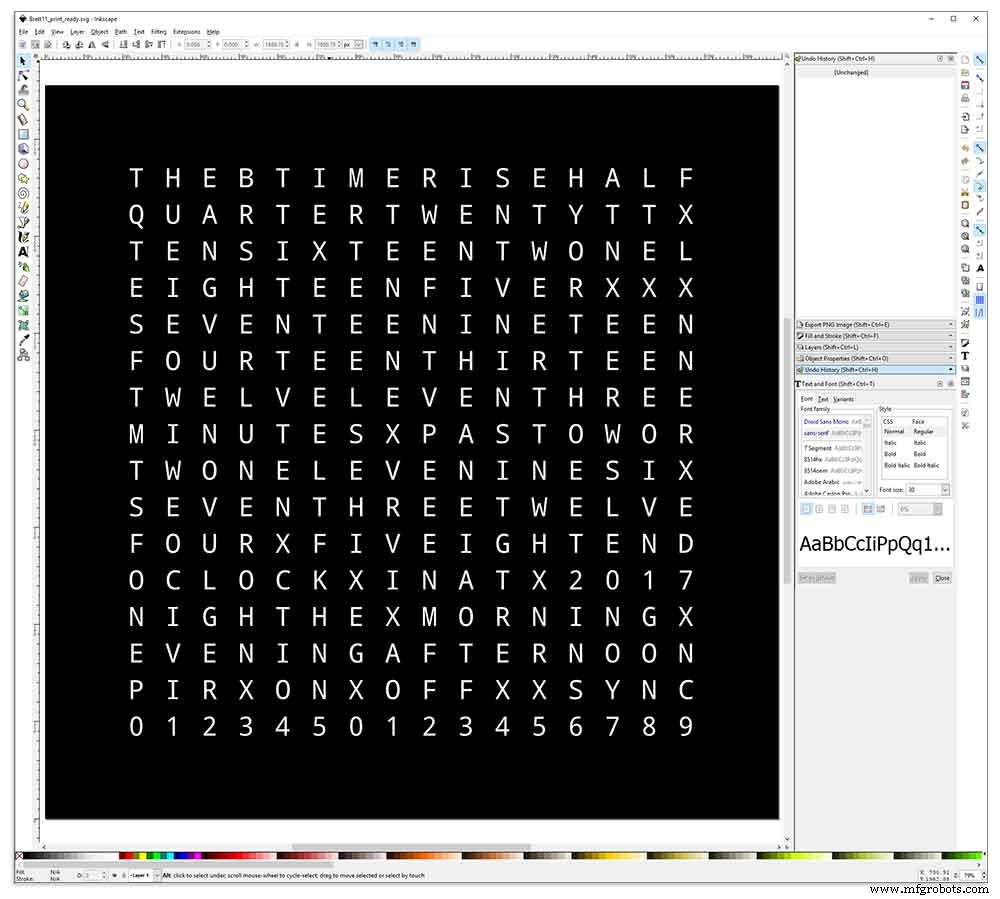
L'autocollant en vinyle est conçu dans Inkscape.
Inkscape est un logiciel de graphisme vectoriel de qualité professionnelle qui fonctionne sous Windows, Mac OS X et GNU/Linux. Il est utilisé par les professionnels du design et les amateurs du monde entier pour créer une grande variété de graphiques tels que des illustrations, des icônes, des logos, des diagrammes, des cartes et des graphiques Web.
Inkscape utilise le standard ouvert W3C SVG (Scalable Vector Graphics) comme format natif et est un logiciel gratuit et open source.
J'ai téléchargé la conception originale d'Inkscape par Wouter Devinck à partir de son référentiel GitHub, puis je l'ai modifiée dans Inkscape pour l'adapter à ma conception. J'ai essayé de nombreuses versions différentes sur mon prototype miniature avant d'envoyer le design final à imprimer.
N'oubliez pas d'imprimer l'autocollant au verso !
J'ai utilisé une société appelée Regal Signs &Graphics qui m'a fourni mon autocollant en vinyle noir, coupé à l'envers, le lettrage éliminé et fourni avec un ruban d'application le tout pour environ 27 £ TTC.
Bien qu'ils soient assez locaux pour moi, j'ai payé un peu plus et j'ai reçu mon autocollant dans un joli tube en carton sécurisé.
J'ai eu quelques problèmes pour obtenir le design dans le bon format pour leur machine, mais à la fin, je l'ai envoyé d'Illustrator au format eps, les personnes très serviables de Regal Signs l'ont réduit à la bonne taille pour moi. Mon fichier Inkscape peut être téléchargé ici AUTOCOLLANT VINYLE.
L'autocollant en vinyle est venu de Regal Signs avec les lettres éliminées, ce qui m'a permis de gagner beaucoup de temps. L'autocollant est livré avec un ruban en plastique sur la face avant (verre) et un papier d'application à l'arrière. Habituellement, vous retirez le ruban adhésif latéral, appliquez l'autocollant, puis retirez le papier d'application. J'ai décidé de laisser le papier d'application car il servait de diffuseur pour les LED. Alors que je laissais le papier d'application dessus, j'ai coupé l'excès de papier autour de l'autocollant avant de l'appliquer.
L'application de l'autocollant était relativement facile. Assurez-vous simplement de regarder quelques vidéos YouTube sur l'application d'autocollants en vinyle sur du verre avant de l'essayer vous-même.
Verre

L'horloge utilise du verre flotté de 4 mm et a été coupée à exactement 500 mm x 500 mm. Comme les bords sont exposés, les bords ont également été polis. Tout cela a été fait par mes vitriers locaux pour 20 £.
Des trous de 5 mm ont ensuite été percés dans le panneau de verre à l'aide d'une perceuse à verre de 5 mm. Regardez des vidéos YouTube sur la façon de percer des trous dans le verre.
J'ai d'abord nettoyé le verre avec de l'acétone et je me suis assuré qu'il était sans poussière (très important). J'ai ensuite mis des gants en plastique pour m'assurer de ne pas avoir de traces de doigts sur l'autocollant.
J'ai vaporisé le verre avec un mélange d'eau et de savon très dilué, puis j'ai retiré très lentement le film plastique de l'autocollant pour révéler la surface avant.
Il est important de décoller le film lentement et à un angle très aigu afin que les lettres de l'autocollant restent connectées au papier de transfert. Une fois l'autocollant complètement exposé, appliquez-le sur la surface de verre humide.
Le mélange eau/savon vous permettra de déplacer l'autocollant au bon endroit sur le verre. Utilisez ensuite une carte de crédit et éloignez-vous du centre de l'autocollant pour éliminer les bulles d'air. Laissez l'autocollant sécher pendant la nuit, puis à l'arrière de l'autocollant, découpez le vinyle sur les 4 trous de montage dans le verre.
Brett11_print_ready.svg
Étape 15 : Construction des cartes principales, partie 1
Cartes principales
La carte principale de l'horloge est composée de 2 feuilles de MDF de 14 mm. La feuille arrière est 10 mm plus petite que la feuille supérieure sur tous les côtés sauf en haut. Le dessus a des bords blancs tandis que le dos a des bords noirs. Lorsqu'elle est vue sur le mur, l'horloge apparaîtra alors comme ayant une profondeur de 14 mm.
La carte principale de l'horloge est composée de 2 feuilles de MDF de 14 mm. La feuille arrière est 10 mm plus petite que la feuille supérieure sur tous les côtés sauf en haut. Le dessus a des bords blancs tandis que le dos a des bords noirs. Lorsqu'elle est vue sur le mur, l'horloge apparaîtra alors comme ayant une profondeur de 14 mm.
Sur l'horloge Wouter Devinck d'origine et la version "catalane" de Pijuana, une seule feuille de MDF de 18 mm d'épaisseur est utilisée avec le dos acheminé pour faire de la place pour le PCB et les composants. L'utilisation de 2 feuilles de MDF signifie que le panneau arrière peut être simplement découpé à l'aide d'une scie sauteuse plutôt que le routage fastidieux et poussiéreux. La feuille supérieure mesure 503 mm x 503 mm pour donner un chevauchement de 1,5 mm autour du verre. Cela protégera un peu le verre des chocs.
Le panneau arrière est découpé à l'aide d'une scie sauteuse et laisse 14 mm d'espace pour les composants.
Les circuits imprimés les plus profonds, y compris les composants, sont les modules MAX 7219 d'une profondeur de 10 mm. Une fois terminé, le panneau arrière est collé ou vissé au panneau avant.
Construction du panneau avant
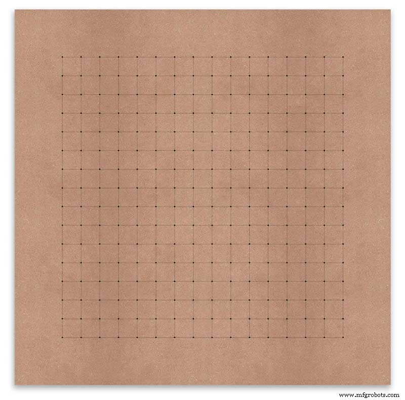
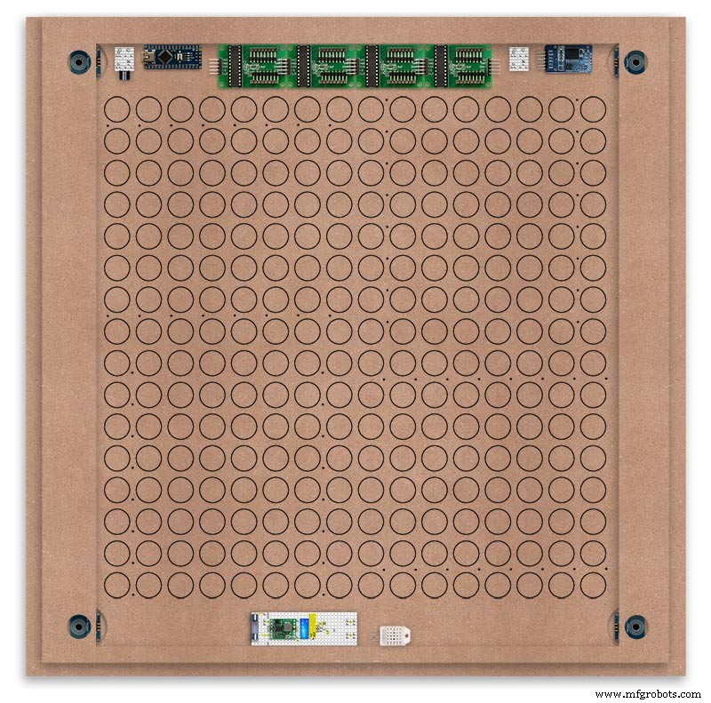
La carte avant contient les 256 LED qui brillent à travers des trous de 6,5 mm et des trous fraisés plus larges de 18 mm pour éclairer les lettres et les chiffres individuels sur l'écran.
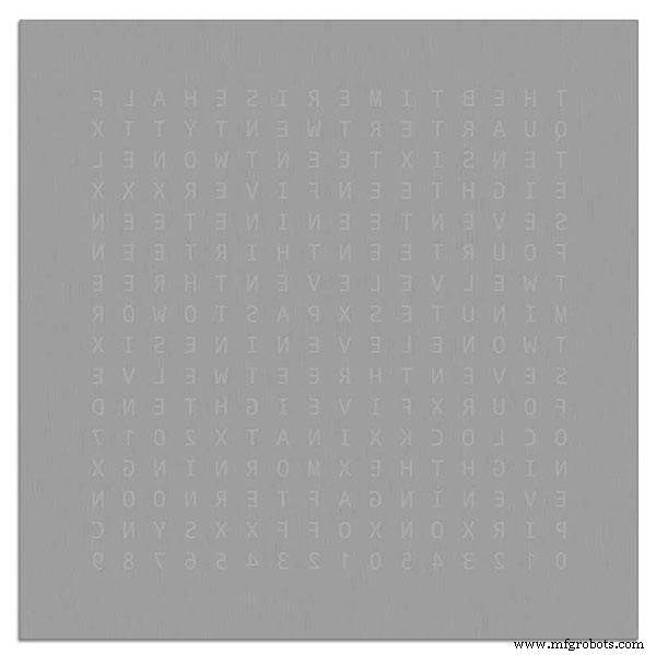
Le tableau est marqué pour montrer la position de perçage au centre de chaque caractère d'affichage. À l'aide d'un écran de 500 mm, j'ai mesuré ma feuille de vinyle et les caractères sont distants de 25 mm à partir de 62,5 mm des bords. J'ai tracé ces lignes sur le MDF, les intersections étant les points de perçage.
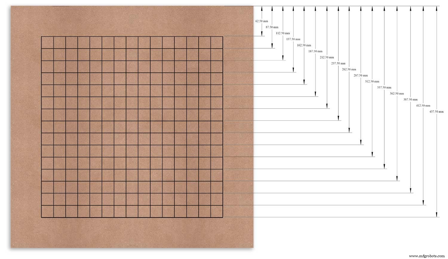
J'ai utilisé le bord supérieur comme point de référence que j'ai mesuré et j'ai marqué chaque rangée à partir de ce point.
Cela a été répété pour la colonne verticale en utilisant le bord gauche comme référence.
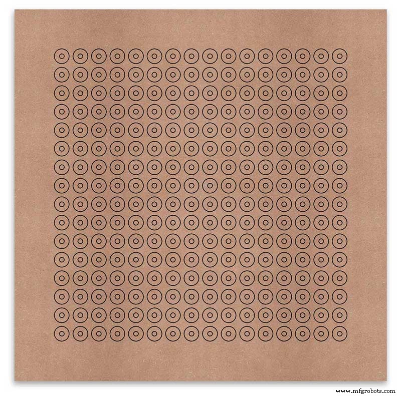
Les intersections de la grille seront le point central des trous de montage des LED de 6 mm et des trous fraisés de 18 mm.
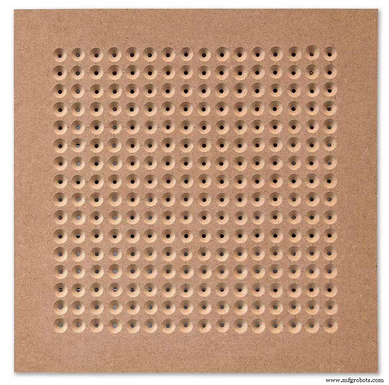
Using an automatic centre punch ( use a nail or screw if you don't have one) I punched the 256 intersection points of the grid.
Using a drill bit to suite your LEDs (6mm in my case) and using the punched holes as a guide for the drill bit drill out all 256 LED mounting holes.
The next task is to drill the 256 18mm countersunk holes using a 20mm countersinking bit.
To keep the countersunk holes at a uniform depth and width I built a countersinking jig using an off cut of wood. To make the jig a hole is drilled in the wood off cut to just fit the silver rotating bezel of my drill chuck. Using a test piece of MDF the countersinking bit is then moved in and out of the chuck until a countersunk hole of the correct diameter is made when drilling through the hole upto the chuck in the off cut of wood. Once the correct distance is found the chuck is tightened and the main board is drilled 256 times by centring the hole in the wood over the existing 6mm holes then drilling down until the chuck bezel hits the hole in the countersinking jig.
Completed front board with 256 countersunk holes and 6mm holes for the LEDs.
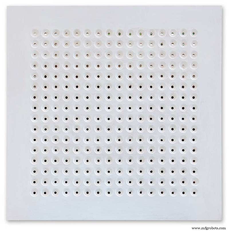
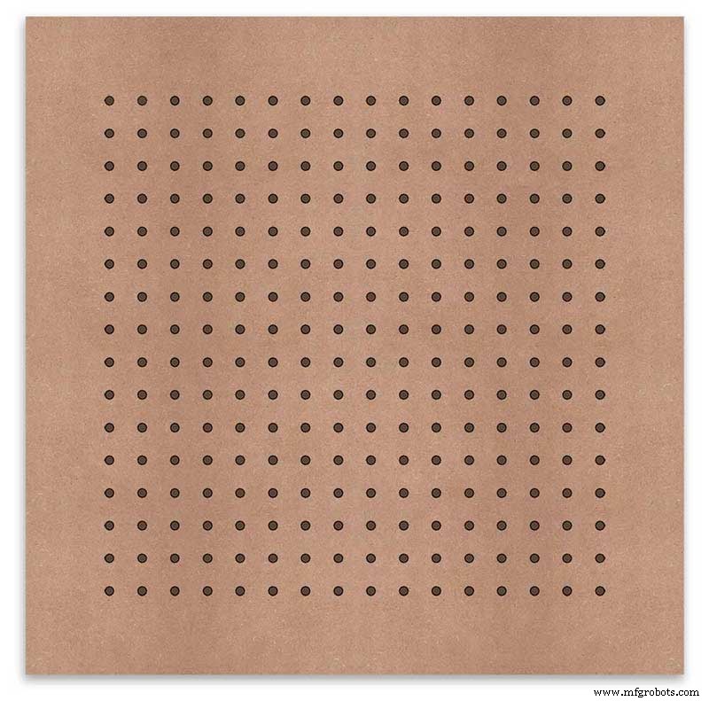
The board is then rubbed down and primed using MDF primer and painted white so the countersunk holes reflect the light from the LEDs.
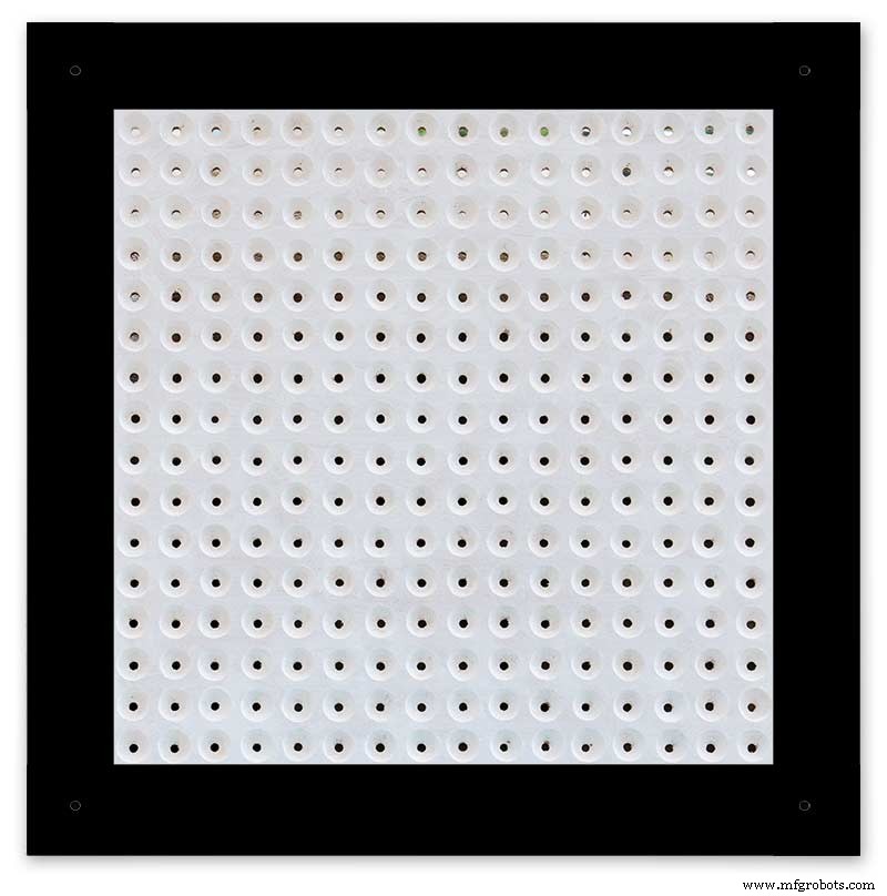
A black edge is painted around the outside edge to hide the board as the glass is 1mm shorter all round. This setback also helps the glass disappear from view on the final clock.
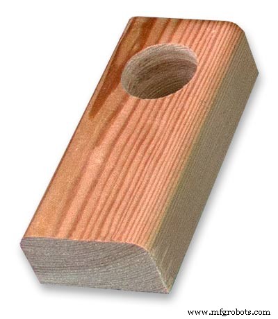
Four 5mm holes are then drilled in the corners to take the Chicago Fasteners. The Chicago Fasteners hold the glass in place, hold the touch sensors and provide a touch sensitive pad on top of the glass. The fasteners have 3mm shafts and will have a small bit of rubber tape wrapped around the shafts to protect the glass.
Turn the board over and drill a rebate with a forstner bit to take the four touch sensors. This hole will be offset from the hole drilled in the previous step.
Wall Mounts
The clock is fixed to the wall by two metal picture hanging mounts.
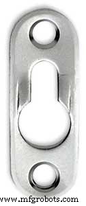
These are recessed into the frame so the highest point of the bracket is level with the frame.
Two 2" countersunk No6 screws sit in these bracket and hold the clock to the wall with a bit of tension so the dust seal is compressed.
Step 16:Construction Touch Sensor Mounting
The touch sensor modules are fixed to the front panel using the Chicago Fastener bolts. The Chicago Fastener bolts then act as touch sensors.
A 5mm hole is drilled through the sensor pad on the module to allow the Chicago Fastener bolt to pass through.
The sensor pad is insulated by the MDF panel and a plastic washer.
The touch pad on the sensor module has a 5mm mounting hole drill through the sensor.

Touch sensors in rebates behind rear panel. Holes drilled into rear panel allows access to the Chicago Fasteners that hold the sensors/glass front in place.
Clock front panel with four Chicago Fastener tops acting as touch plates.
Step 17:Electronic Components &Modules
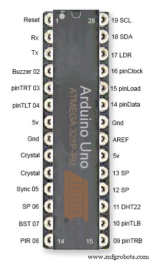
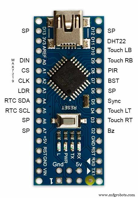
ATmega328 pin connections in case you want to prototype the circuit on an Arduino Uno. Note BST pin 07 is not used.
Pin label numbers refer to Arduino IDE numbers.
LEDs
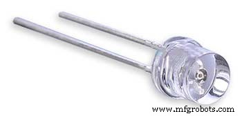
Make sure you purchase your LEDs from a good source. These LEDs will be on for many hours a day. I have has problems with LEDs failing after a few weeks use.
My LEDs Specs
5mm White Flat Top LEDs offering a pure and consistent colour with a wide angle ultra bright light output.
Colour :White
Quantity :256
Lenses Type :Round Flat Top
Crystal ClearBrightness :13000mcdForward
Voltage :3.2v - 3.8v
Forward Current :20mA (typical), 30mA (Max)
Viewing Angle :120 degrees
DHT22 Temperature &Humidity Sensor
The DHT22 is a basic, low-cost digital temperature and humidity sensor. It uses a capacitive humidity sensor and a thermistor to measure the surrounding air, and sends out a digital signal on the data pin.
You can only get new data from it once every 2 seconds, so sensor readings can be up to 2 seconds old.
Simply connect the first pin on the left to 3-5V power, the second pin to your data input pin and the right most pin to ground.
To prevent the temperature of the inside clock case being measured the top and left side vent of the DH22 are covered over with tape. This also stops dust being drawn into the clock case.
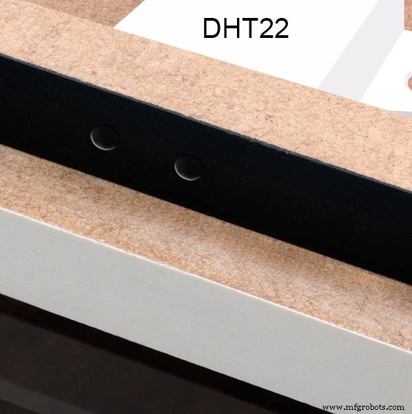
The DHT22 is mounted with its right open side mounted tight against the lower rear cover.Two small holes are drilled in the lower edge of the rear MDF board to allow air from the room to circulate around the sensor.
Arduino NANO
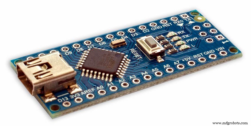
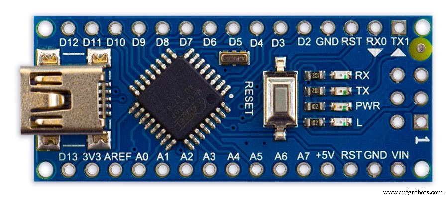
PowerThe Arduino Nano can be powered via the Mini-B USB connection, 6-20V unregulated external power supply (pin 30), or 5V regulated external power supply (pin 27). The power source is automatically selected to the highest voltage source.
Memory
The ATmega328 has 32 KB, (also with 2 KB used for the bootloader.
The ATmega328 has 2 KB of SRAM and 1 KB of EEPROM.
Input and Output
Each of the 14 digital pins on the Nano can be used as an input or output, using pinMode(), digitalWrite(), and digitalRead() functions. They operate at 5 volts. Each pin can provide or receive a maximum of 40 mA and has an internal pull-up resistor (disconnected by default) of 20-50 kOhms. In addition, some pins have specialized functions:Serial:0 (RX) and 1 (TX). Used to receive (RX) and transmit (TX) TTL serial data. These pins are connected to the corresponding pins of the FTDI USB-to-TTL Serial chip.
External Interrupts:2 and 3.
These pins can be configured to trigger an interrupt on a low value, a rising or falling edge, or a change in value. See the attachInterrupt() function for details.
PWM:3, 5, 6, 9, 10, and 11. Provide 8-bit PWM output with the analogWrite() function.
SPI:10 (SS), 11 (MOSI), 12 (MISO), 13 (SCK). These pins support SPI communication, which, although provided by the underlying hardware, is not currently included in the Arduino language.
LED:13. There is a built-in LED connected to digital pin 13. When the pin is HIGH value, the LED is on, when the pin is LOW, it's off.
The Nano has 8 analog inputs, each of which provide 10 bits of resolution (i.e. 1024 different values). By default they measure from ground to 5 volts, though is it possible to change the upper end of their range using the analogReference() function. Analog pins 6 and 7 cannot be used as digital pins. Additionally, some pins have specialized functionality:I2C:4 (SDA) and 5 (SCL). Support I2C (TWI) communication using the Wire library (documentation on the Wiring website).
There are a couple of other pins on the board:AREF. Reference voltage for the analog inputs. Used with analogReference(). Reset. Bring this line LOW to reset the microcontroller. Typically used to add a reset button to shields which block the one on the board.
Communication The Arduino Nano has a number of facilities for communicating with a computer, another Arduino, or other microcontrollers. The ATmega328 provide UART TTL (5V) serial communication, which is available on digital pins 0 (RX) and 1 (TX). An FTDI FT232RL on the board channels this serial communication over USB and the FTDI drivers (included with the Arduino software) provide a virtual com port to software on the computer. The Arduino software includes a serial monitor which allows simple textual data to be sent to and from the Arduino board. The RX and TX LEDs on the board will flash when data is being transmitted via the FTDI chip and USB connection to the computer (but not for serial communication on pins 0 and 1). A SoftwareSerial library allows for serial communication on any of the Nano's digital pins. The ATmega328 also support I2C (TWI) and SPI communication. The Arduino software includes a Wire library to simplify use of the I2C bus. To use the SPI communication, please see ATmega328 datasheet.
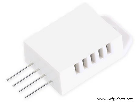
TTP223 Touch Sensor Module
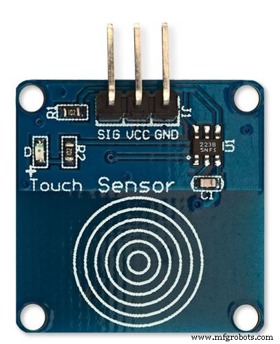
The touch Sensor Module is bolted to the front panel using the glass mounting bolts. The bolt goes through a 5mm hole drilled in the middle of the sensor.Note the mounting bolt is touched to trigger the sensor but is insulated from the sensor itself through plastic washers. Four of these modules are used in the clock one mounted on each corner of the glass.
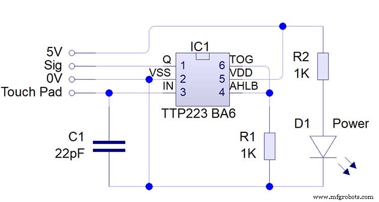
Note the LEDs are not required and are removed from the modules (just break them off) to save power.
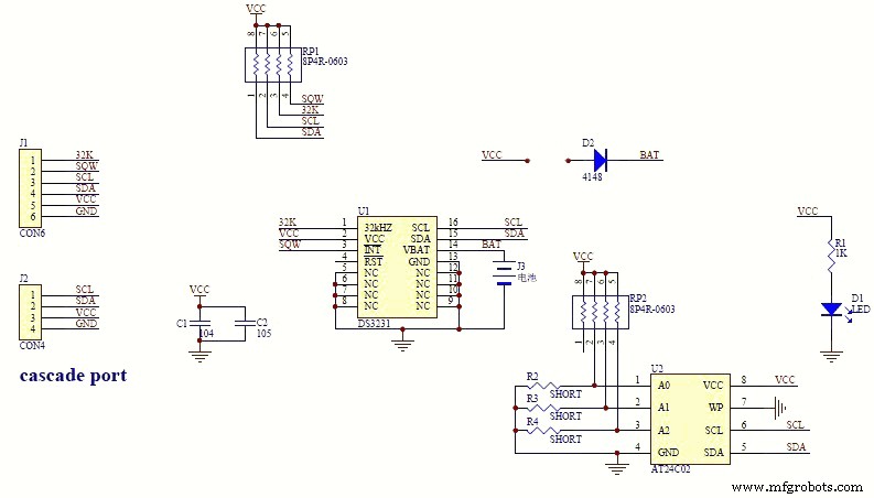
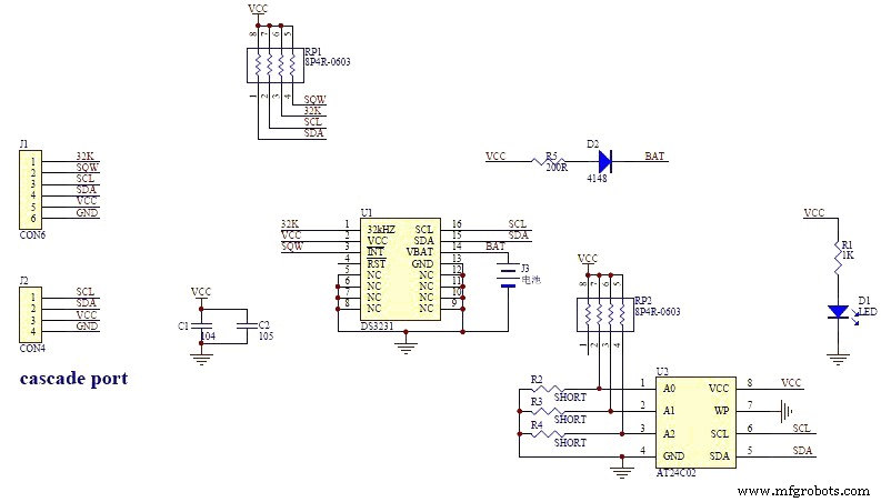
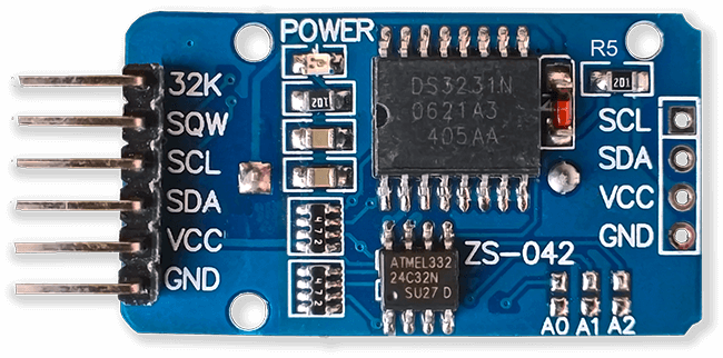
DS3231 AT24C32 I2C Precision Real Time Clock Module
My clock uses a DS3231 AT24C32 I2C Precision Real Time Clock Module.The module comes supplied with a Lithium-Ion rechargeable battery see diagram below. I use a non rechargeable battery so have removed resistor R5 from the module.
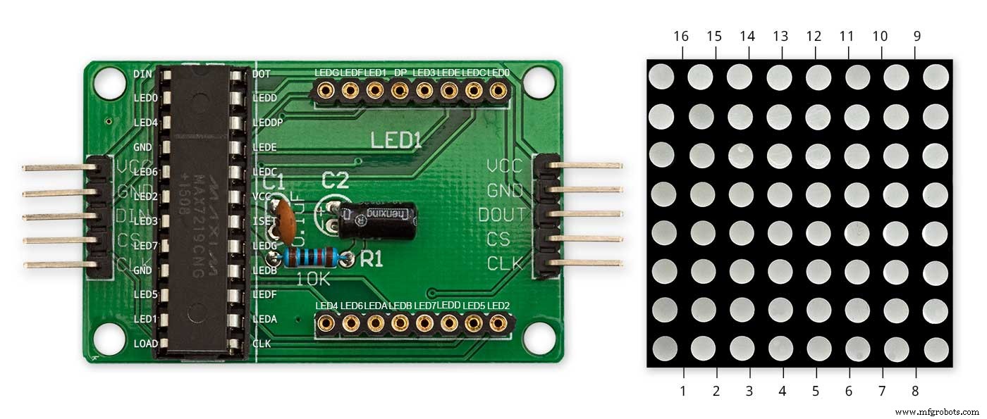
MAX7219 Display Module
MAX7219 LED current limiting
The max current through the LEDs is set by a single resistor R1 on the module. The value of resistor can be found from the table below.
The module comes with a 10K resistor preinstalled but this can be removed and a resister to match your LEDs current added in its place. My LEDs Forward Voltage is 3.2v - 3.8v @ 20mA. They can handle 30mA max but for long LED life 20mA is best. I have used 22KΩ resistors which will limit the current to around 20mA when the light levels are at their peek.
See setting automatic brightness levels.
1088AS LED Dot Matrix display

1088AS LED Dot Matrix display view of lower edge Pins 1 to 8 left to right.
This is used for prototyping and is not required in the final project.
LDR
An LDR is used to sense the ambient light levels. The LDR is around 500Ω in bright light and 10MΩ in the dark.
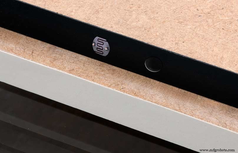
The LDR is positioned underneath the clock on the rear MDF panel.
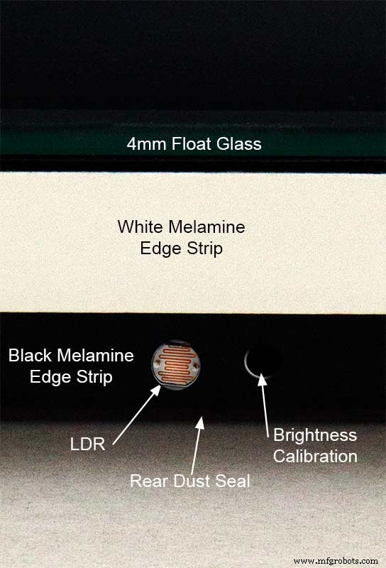
Next to the LDR is a hole to give access to the trimmer resister to calibrate the LED brightness control.
Component List
Step 18 Dust Seals
To prevent ingress of dust two dust seals are fitted.
On the rear MDF board a 2mm soft foam rubber dust seal is fitted. When the clock is hung on its hanging hooks the seal is under pressureand seals the back of the clock to the wall.
The seal is self adhesive and is fitted with a 5mm gap to the edge of the rear MDF board.
On top of the front board to prevent dust getting under the glass a strip of self amalgamating rubber is fitted 5mm from the board edge.
To prevent the glass from cracking when the Chicago bolts are tightened 4 small square of rubber are also fitted around the holes in the glass.
I punched holes for the Chicago Bolts in the rubber with a leather punch.
Step 19:Schematic
Nano Connections
The connections to the Arduino Nano. Download the full size file from the hardware section
MAX2719 connections


The 4 MAX7219 modules and the connected LED matrixes.
Note the LED display matrixes are rotated anti-clockwise 90 degrees from each other starting from display matrix 01.Display Matrix 01 input is wired to the Arduino CLK, DIN and LOAD the output is taken to the input of Display matrix 02 etc etc.
Step 20:Wiring Building the LED Matrixes
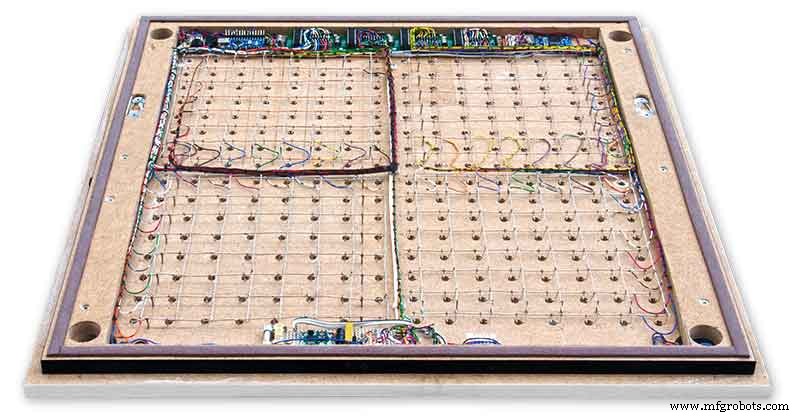
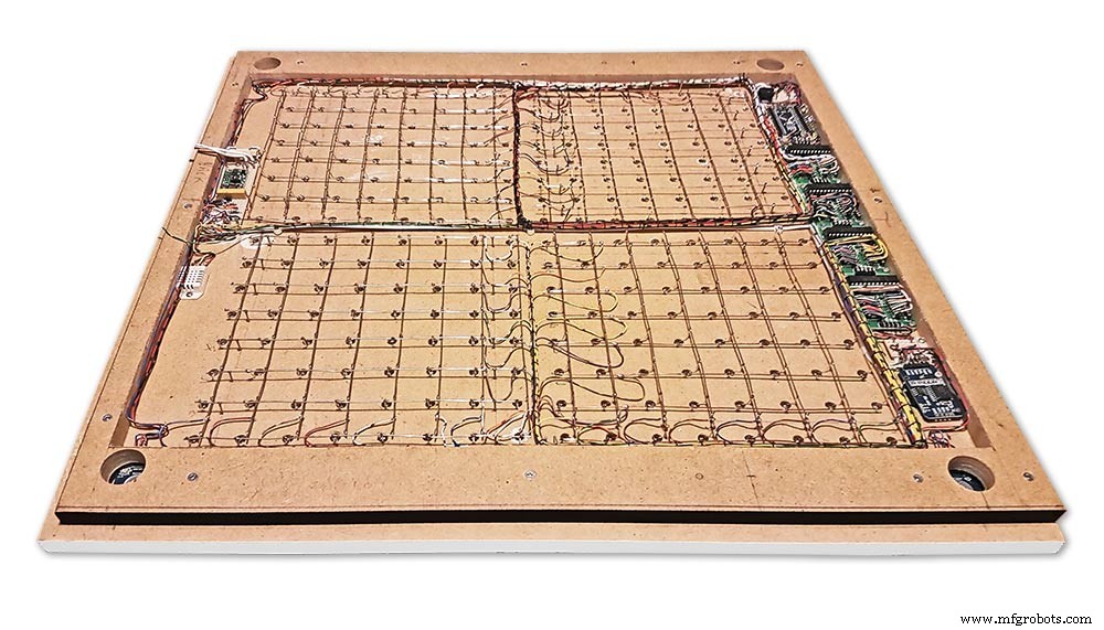
Module Locations

The module locations are shown above. The four sensors are located in the recesses on the main board behind the rear board. Holes are cut into the rear board to allow access for fit the Chicago Bolts/Sensor pads.
The four MAX7219 Display Modules are soldered together and are mounted in the centre top of the board. This keeps the data links between the boards as short as possible.
The Arduino Nano is mounted on the left of the MAX7219 Display Modules and the RTC on the right. The RTC battery holder on the base of the RTC module is recessed into the main board.
The Vero board containing the power module is located on the lower part of the board. There are two power distribution boards mounted on the top of the clock. The main 5v 2A feed cable is taken to both of these boards and power is then distributed to the other boards from these points.
The MAX7219 board power is fed from the left board and daisy chained through each board then taken out the forth board to ensure they are fed with 0v and 5v from both ends.
The LED locations are shown. The LED matrixes each contain 64 LEDs and are labelled 1 to 4.
These correspond to the 4 MAX 7219 modules mounted above numbered 1 to 4 left to right. Note this is the rear of the clock so number will be revearsed.
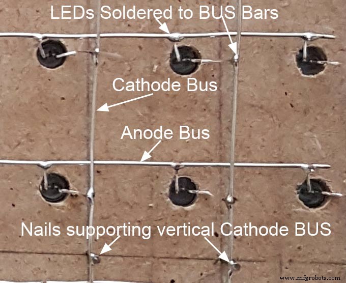
The LED Matrixes are built up off 2 types of BUS Bars per module. A Cathode Bus at 10mm high and an Anode BUS bar at 2mm high.
There are 8 Cathode and 8 Anode BUS Bars per module. Each module has 16 x 15mm panel pins hammered into the board in the position shown to support the 10mm high Cathode BUS.
The 15mm panel pins are hammered in 5mm (I used a 10mm piece of metal bar as a gauge) leaving 10mm as Cathode BUS bar support pins.
As shown above the pins correspond with the thick parts of the board not the recess for the LEDs on the front of the board. Note the LED recess is on the front of the board and can't be seen from the back.

0.9mm copper wire is then soldered to each pair of pins to form the Cathode BUS Bar.
Note the rotation of each module and also the modules are in reverse as it is the back of the board the LEDs are connected to.
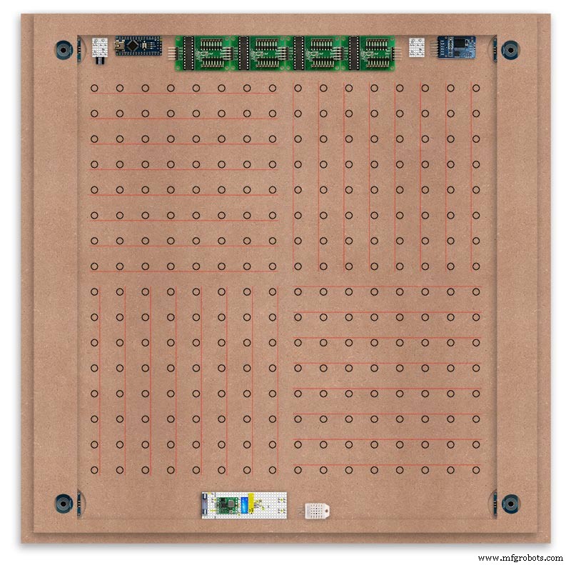
The Anode BUS Bars are shown below in Red and are supported off each LED Anode about 2mm off the MDF board. No Pins required.

Both Cathode &Anode BUS Bar locations are shown below.
Each LED is connected to an Anode and Cathode of the Matrix.
Step 21:Wiring the LEDs
LEDs
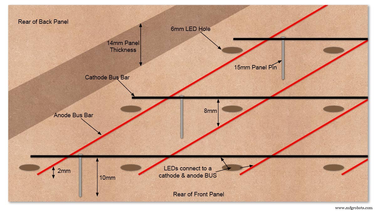
Diagram showing Bus Bar layout with panel pins supporting the Cathode Bus. This module has horizontal Cathode and vertical Anode Bus Bars.
Close up section of Module wiring.The Cathode BUS Bars run vertically and the Anode BUS Bars run horizontally on this module. The Anode &Cathode BUS Bars have an 8mm vertical separation.
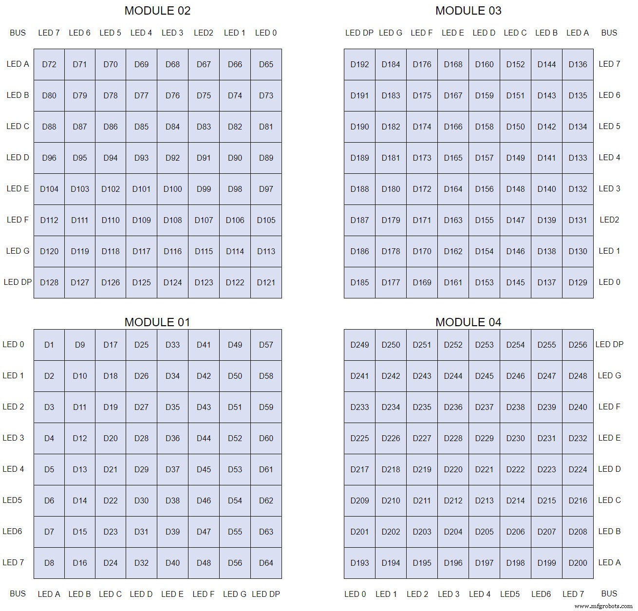
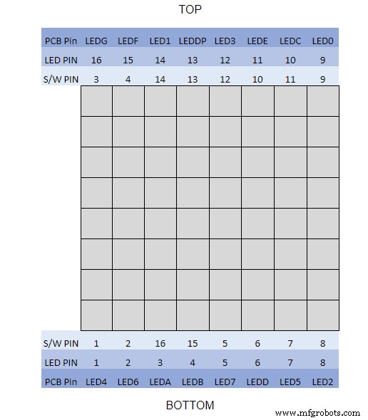
The LEDs are connected to the matrixes and MAX7219 modules from the rear. The LED positions will be reversed and of course rotated 90° relative to the next module. This makes it very complicated connecting the correct LEDs and Bus bars from the rear of the board. The table below shows the LED positions in the blue boxes with the BUS Bar matrix position in black around the outside as they appear from the back of the front MDF board.
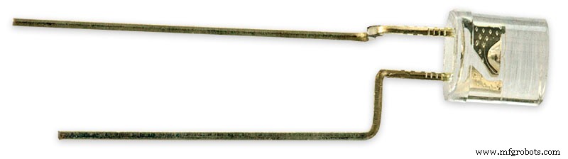
The LEDs are bent in a jig to keep the position in the display constant and to speed up construction. Each LED has four bends two on each leg that's 1024 in total! The Cathode leg is bent 90° from the Anode.
The Matrix grids are wired to the corresponding pins on the MAX7219 modules according to the layout table.
There are 16 wires to each module.
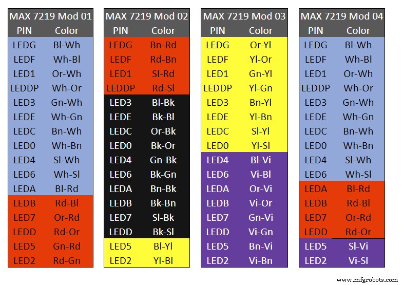
Table 1 Module LED Matrix Wiring Colour Code is shown above.
Each Module has 16 wires connecting it to the LED Matrixes. I have used 50pr 0.5mm cable so the last 14pr colours are duplicated. On Mod 4 I went out of order and missed out the Sl/Vi at the start so have put it in at the end.
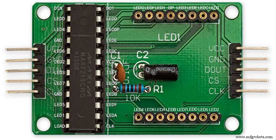
Step 22:Wiring Modifying the MAX7219 Modules
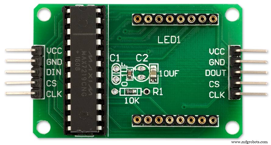
Before wires can be connected to the MAX 2917 modules they will need to be modified.
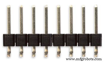
Two sets of 8 90° pin connectors will to be soldered to the lower edge of the existing LED matrix connector.

Modified MAX7219 module with 90° pin connectors soldered in place to the bottom of the old LED Matrix connectors.
Wires are taken away from these points to the LED matrix on the main MDF board as per the LED Matrix Wiring Colour Code table on the previous step.
Side view showing the pins soldered to the side of the old LED Matrix connector pins just above the PCB.
Note if your MAX7219 Module does not have surface mount components the 90° pin connectors may need to be trimmed back so they don't foul R1, C1 or C2.
MAX7219 LED current limitingThe max current through the LEDs is set by a single resistor R1 on the module. The value of resistor can be found from the table below.

The module comes with a 10K resistor preinstalled but this can be removed and a resistor to match your LEDs current added in its place.
My LEDs Forward Voltage is 3.2v - 3.8v @ 20mA. They can handle 30mA max but for long LED life 20mA is best. I have used 22KΩ resistors which will limit the current to around 20mA when the light levels are at their peek.
Note this sets the max current through your LEDs actual brightness is controlled by the LDR/software/ trimmer resistor and will usually be far less than this.
Setting Automatic Brightness Levels
The clock automatically senses the ambient light and adjusts the LEDs accordingly.
When first installed the clock will need to be calibrated to the maximum light levels in its actual location.

Connect a mobile, laptop/tablet etc via a suitable cable to the mini USB port of the clock and open an app to monitor the serial port.
I use Slick USB 2 Serial Terminal on my S7 via an OTG cable and USB to mini USB cable.
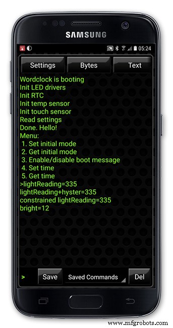
The clock will reboot and after the initial start screen you will see the following data updating down the screen.
You don't need to worry about lightReading or constrained lightReading+hyster just light reading, and bright.
With the clock in position and the ambient light at its maximum levels carefully insert a flat bladed jewellers screwdriver into the access hole just to the right of the light sensor.
Turn the screwdriver slowly until the light reading =600 (or your level set in brightness.cpp) and bright =15.
Your clock will now go to max brightness when the ambient light is at its maximum.
If you turn the screwdriver too far the light reading will go over 600 but the bright reading will not increase.
If you want the clock to be dimmer right across the range of ambient light levels adjust the light reading to a level less than 600 at max ambient light levels.
Note when bright=15 this will output the max current to the LEDs. The max current is set by R1( RSET) on the MAX7219 module and this should be chosen for your type of LED used in the display.
Step 23:Wring Mini USB Port
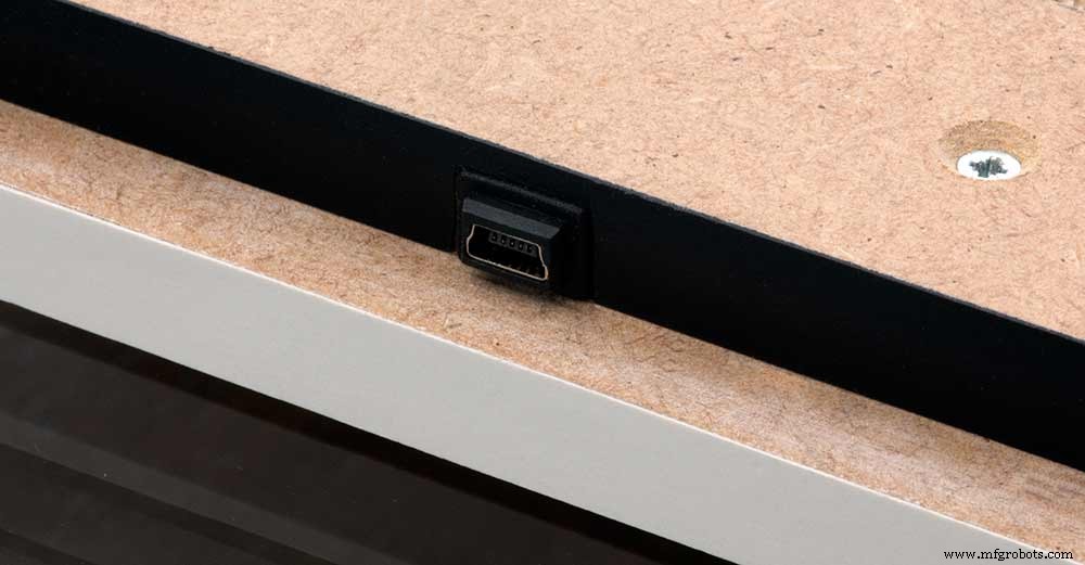
To allow adjustment/checking of light levels and programming of the clock a Mini USB socket is cut into the right hand side of the rear MDF sheet.
I have used a 25cm 90° Right angle Mini USB Male to Female Extension Cable and stripped back the insulation sleeve and shielding to expose the wires. This allows the cable to bend around the sharp angles and tight spaces of the enclosure.
Step 24:PIR Controlled Display Shutdown
This is optional as a Doppler Radar module can be fitted inside the clock instead.
See next section.
The PIR when enabled on the word clock menu (bott left PIR On, bott right PIR Off) turns on the display when movement is detected in the room.
When no movement is detected the display turns off after a set period of time. When the PIR is enabled the displays shows "PIR ON" and when disabled (display always on) it shows "PIR OFF" Note when the PIR is not enabled the display is always On.
The PIR module is fitted remote from the clock in a modified chrome light switch box. The box is cut into a plasterboard wall and also contains a switch to turn the clock off. The module itself is very small and can be mounted in a tiny enclosure if you don't want it on show. It will not work behind glass so if you wanted to mount it on the clock a hole would need to cut in the glass. This is very easy to do with a large hole cutter.
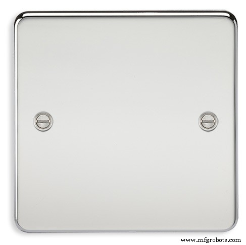
A blank chrome switch plate and back box are used to house the power switch and PIR module.
Two holes are drilled in the blank switch plate for the power switch and PIR lens.
The hole are centre punched, pilot drilled and then drilled out just big enough for a step cutter to fit through. The hole for the PIR diffuser is cut just big enough for the lens to go through with a friction fit.
The completed switch plate.
The 12 volt supply +ve is terminated on the switch with the 0v terminated on the earth screw.
12 volts is then fed back upto the clock PSU Vero board from the other side of the switch and again the earth screw. 5 volts are fed from the clock PSU Vero board to supply the PIR module.
The 5 volts and PIR sensor wire to the clock terminate on PCB header sockets. These are is plugged into the PIR Module header pins. The sync cable is terminated on a header pins and connects to the Master Clock 30 second sync cable via a single header socket.
The PIR has 2 trimmer resistors for adjusting sensitivity and also length of time the PIR &display stay activated.
PIR On/Off Control:The PIR is turned on and off in word clock mode by touching the bottom left sensor to turn the PIR on or by touching the right sensor to turn the PIR off. Note when the PIR is set to off the display stays on permanently. When you change the PIR setting the work "PIR ON" or "PIR OFF" is displayed for 5 seconds.
When initial power up the default is PIR off if you switch the PIR On straight away the display will go off as the PIR takes a minute or so to initialise before detecting movement.
Photo 6 &7 "PIR ON" or "PIR OFF" are displayed for 5 seconds when PIR setting is changed.
Step 25:Doppler Radar Control Option
Optional Doppler Radar Module can be added in place of the PIR above.
The Doppler Radar when enabled on the Word Clock menu (bott left PIR On, bott right PIR Off) turns on the display when movement is detected in the room. A check is made for motion on every quarter hour. When no movement is detected the display turns off until movement is detected again.
When the PIR is enabled the displays shows "PIR ON" and when disabled (display always on) it shows "PIR OFF" Note when the PIR is not enabled the display is always On. Unlike PIR modules the Doppler Radar module can see through glass and plastic and is fixed into the case of the clock behind the glass and PVC sticker. The module has a range of around 5m or 16' 5".
Doppler Radar Module fixed inside the case. A hole is drilled in the front panel to allow the module to monitor the room.
Front panel showing hole through to the Doppler Radar module microwave sensor.
The module is hidden from view behind the PVC sticker and glass.
Step 26:PIR/Doppler Radar On Off Control
The PIR is turned on &off in word clock mode by touching the bottom left sensor to turn the PIR on or by touching the right sensor to turn the PIR off.
Note when the PIR is set to off the display stays on permanently.

When you change the PIR setting the work "PIR ON" or "PIR OFF" is displayed for 5 seconds.
When initial power up the default is PIR off if you switch the PIR On straight away the display will go off as the PIR takes a minute or so to initialise before detecting movement.
Step 27:Setting Automatic Brightness Levels
The clock automatically senses the ambient light and adjusts the LEDs accordingly.
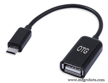
When first installed the clock will need to be calibrated to the maximum light levels in its actual location. Connect a mobile, laptop/tablet etc via a suitable cable to the mini USB port of the clock and open an app to monitor the serial port. I use Slick USB 2 Serial Terminal on my S7 via an OTG cable and USB to mini USB cable.

The clock will reboot and after the initial start screen you will see the following data updating down the screen.
You don't need to worry about lightReading or constrained lightReading+hyster just light reading, and bright.With the clock in position and the ambient light at its maximum levels carefully insert a flat bladed jewellers screwdriver into the access hole just to the right of the light sensor. Turn the screwdriver slowly until the light reading =600 (or your level set in brightness.cpp) and bright =15. Your clock will now go to max brightness when the ambient light is at its maximum. If you turn the screwdriver too far the light reading will go over 600 but the bright reading will not increase.
If you want the clock to be dimmer right across the range of ambient light levels adjust the light reading to a level less than 600 at max ambient light levels.
Note when bright=15 this will output the max current to the LEDs. The max current is set by R1( RSET) on the MAX7219 module and this should be chosen for your type of LED used in the display.
Step 28:Setting the Clock
The clock is set in the digital clock mode by touching the bottom left sensor.
The hour digits will now flash twice a second to indicate the clock is in time setting mode.In this mode the sensors have the following functions.
Top right - steps the hours or mins digits up
Top left- steps the hours or mins digits down
Bottom left 1sr press - enters the time setting mode selecting hours digits
Bottom left 2nd press -selects the mins digits for changing
Bottom left 3rd press -exits time setting mode and sets the time
Bottom right - resets the seconds to 00
Step 29:Synchronisation
If you have connected a 30 second master clock sync cable then the clock will jump back or forward to 30 seconds when out of time setting mode. If you don't have a Master Clock to sync to then the clock will fall back on the on board temperature compensated real time clock which in itself is a very precise quartz clock.
Just reset the seconds roughly in sync to the seconds (within 10 seconds either way) and wait for the clock to sync once out of time setting mode.
The animated loop below shows the Word Clock is running fast by several seconds. A synchronisation pulse is received from the Master Clock every 30 seconds on the minute and half minute synchronising the clock on 30 seconds.
The clock will ignore the 30 second synchronisation pulse from the Master Clock at 0 seconds. Note clock synchronisation only happens when the Word Clock is 20 seconds past and 20 seconds to a minute. In normal operation the sync pulse corrects the clock to within a fraction of a second so you will see the word "SYNC" appear with no visible correction to the seconds.
Note the synchronisation pulse is received every 30 seconds but the clock will ignore pulses at 0 seconds.
Step 30:Software &Making Changes
The software can be downloaded from the software tab and contains the following modules.
Program Files Modules
Brett_wordclock_v4_3.ino Main program, latest update includes shortened code saving 10% in size.
Thanks to srdevil for providing the updated code for this seconds display.
brightness.cpp/.h Brightness autoadjustment
character.cpp/.h Character (digit) definitions
credits.cpp/.h Ending Credits
display.cpp/.h Display &LED functions
life.cpp/.h Game of Life
serial.cpp/.h Serial port setup menu
simon.cpp/.h Simon Says game
temphum.cpp/.h Temperature &Humidity displa
tetris.cpp/.h Tetris game
time.cpp/.h Wordclock, digital clock
timeanalog.cpp/.h Analogue clock
touchbuttons.cpp/.h Touch buttons, mode switching
Third party libraries:
Chronodot.cpp/.h Chronodot library (for DS3231)
DHT.cpp/.h Temperature sensor library (for DHT22)
LedControl.cpp/.h LedControl library (for MAX7219)
stc.cpp/.h/platform.h Simple Tetris Clone library
pitches.h Note frequencies from the Arduino webpage
When you want to make changes to my code you can compare my code to the "Catalan Code" to make it easier to understand what changes you need to make. I have added //Brett to my code to highlight my changes.
Changing the code.
If like me you are not very good at coding just play around with the code to get an understanding of how it works.
I just save a different version each time I make even a tiny change. This way if I mess up I can go back a version and start again.
If you are keeping my linear seconds display update the version number on the display so you know what version you are trying out each time. This is done in the module credit.h around line 47.
It would take far too long to explain all the code but here is a very brief guide on how to change the words and when they are displayed.
The WORDS are set in time.h
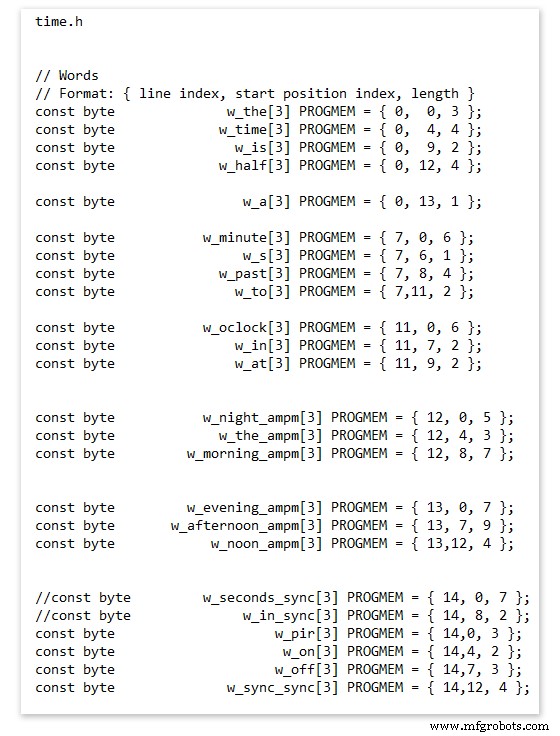
On line 52 we have
const byte w_the[3] PROGMEM ={ 0, 0, 3 };
The word "THE" is described in this line with the LED location in the curly brackets "{ 0, 0, 3 }"
This is the co-ordinate of the LEDs we are gong to light when we call "w_the"
The LED matrix numbers starts top left and start from 0 so "{ 0, 0, 3 }" is the first LED across and down the 3 just means the 3 LEDs across including this one will light. As the letters THE are in this position the word "THE" is displayed.
Similarly the word "TIME" would be lit by lighting the four LEDs here { 0, 4, 4 } or row 0, 5th LED along and light 4 LEDs (remember to count from 0).
Working you way down the page shows the position of all the words.
Controlling when words are lit
This happens in the module time.cpp
Here you just make a list of rules to tell the clock what words to light at certain times.
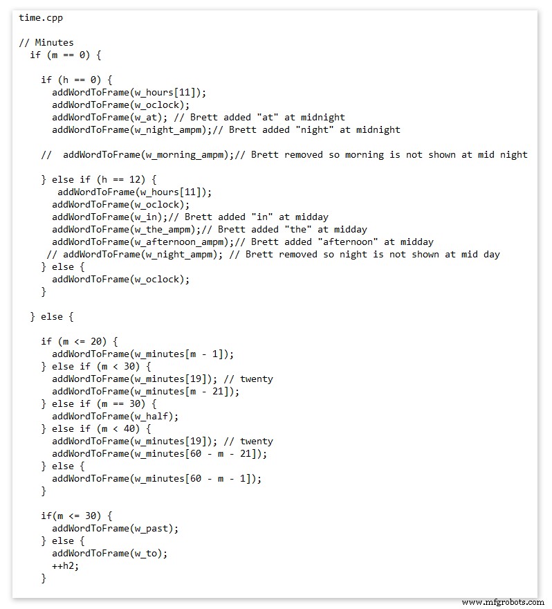
Pic above shows part of the code starting with line 695
At midnight we want to make the clock say "THE TIME IS TWELVE OCLOCK AT NIGHT"
Midnight is 00 00
"THE TIME IS" is always displayed from lines 687
So we add the rules if minutes are 0, then if hours are 0 show the word for hours "TWELVE" and the word "OCLOCK" the word "AT" and the word "NIGHT"
If you follow the code down all the possible time combinations are covered.
Analogue Clock Code Change - increase in time definition One of the comments sent to me by srdevil was some code changes. His comment can be seen below.
I have not had time to test the code but have included it below if you want to try it out.
" If the time is 18:00, it points up (long leg) and down (short leg). But when the time is 18:59, it still points totally down (short leg) so it looks like the time is 17:59 on a normal clock. My brother change the code so that if it is>HH:15 the small pointer moves already to the next number. As of this we also increased the resolution in the part between>HH:15 -
Code on the comments section or can be seen here http://home.btconnect.com/brettoliver1/Word_Clock/Word_Clock.htm#analogeclock
Code
- Brett_wordclock_v4_5.zip
Brett_wordclock_v4_5.zipArduino
Load into Aduino IDENo preview (download only).
Github
https://github.com/wouterdevinck/wordclockhttps://github.com/wouterdevinck/wordclockGithub
https://github.com/svcabre/wordclockhttps://github.com/svcabre/wordclockMy Word Clock on GITHUB
Schematics and code https://github.com/brettoliver/wordclockPièces et boîtiers personnalisés
Vinyl Sticker Design in Inkscape (free to download) change as required brett11_print_ready_6bbpMTDyFa.svgSchémas
Schemaic showing main board connections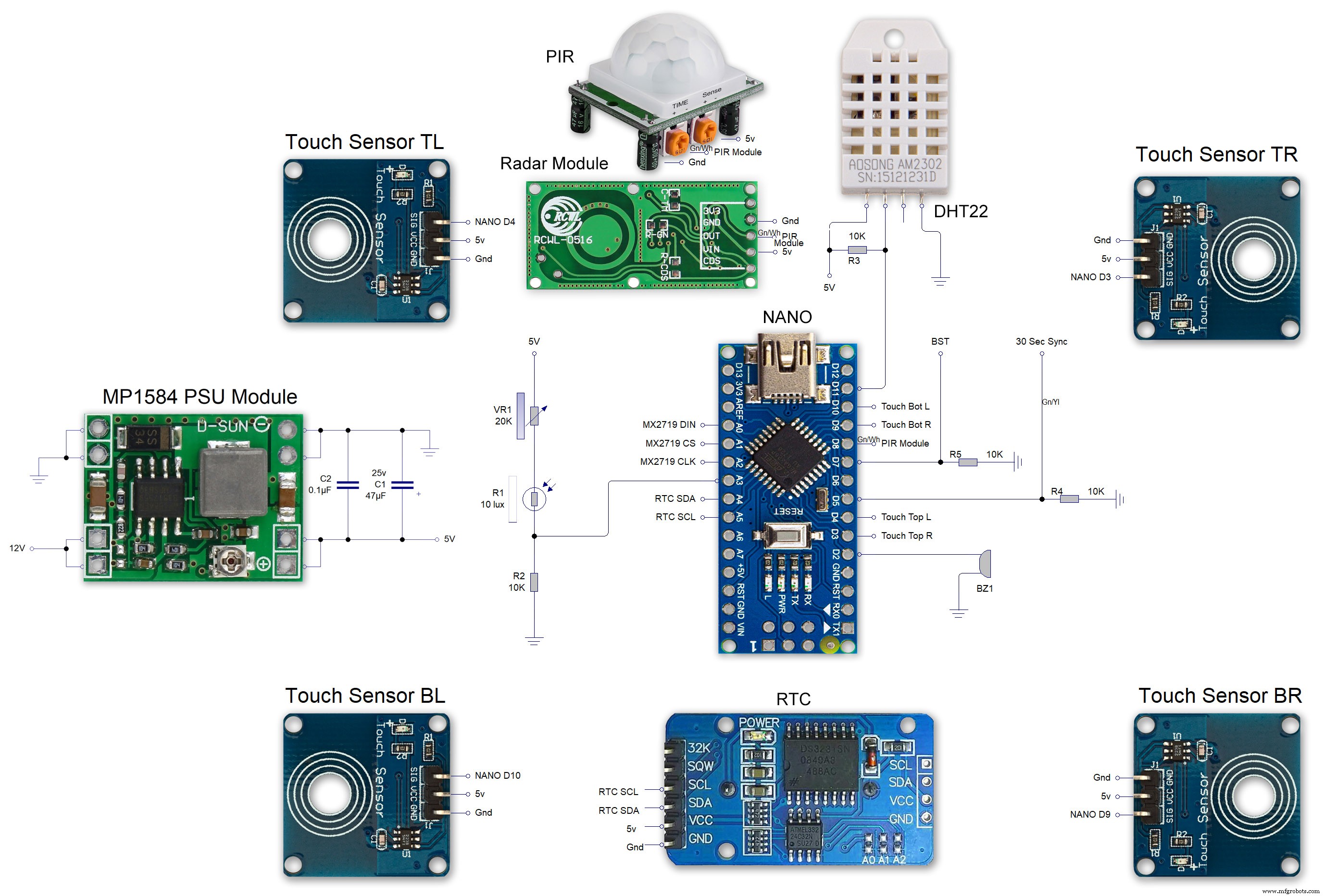 MAX7219 7 segment display module 01 LED connections
 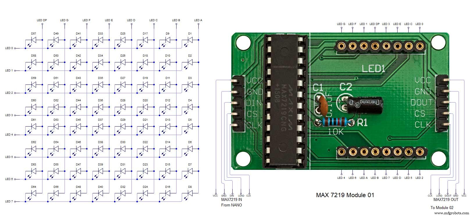 MAX7219 7 segment display module 02 LED connections
 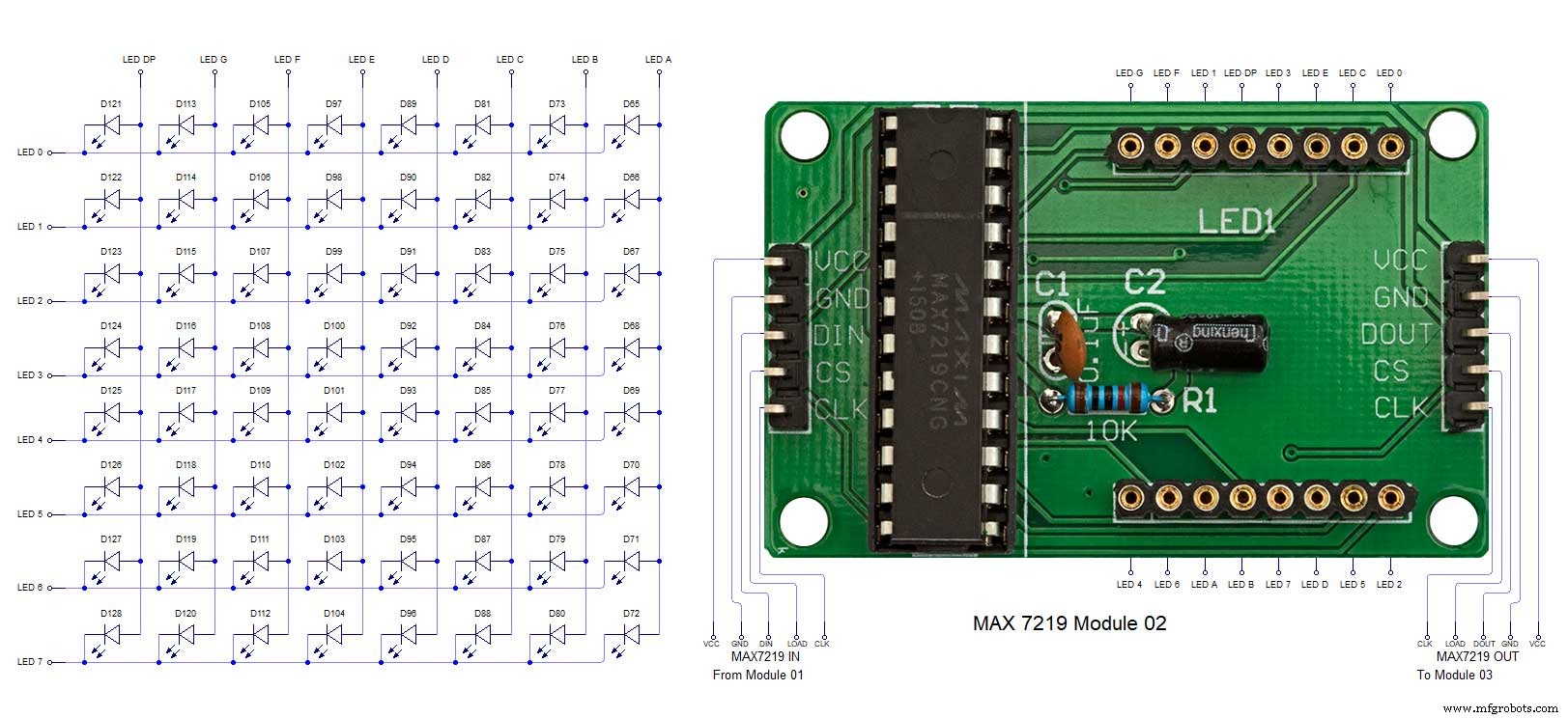 MAX7219 7 segment display module 03 LED connections
 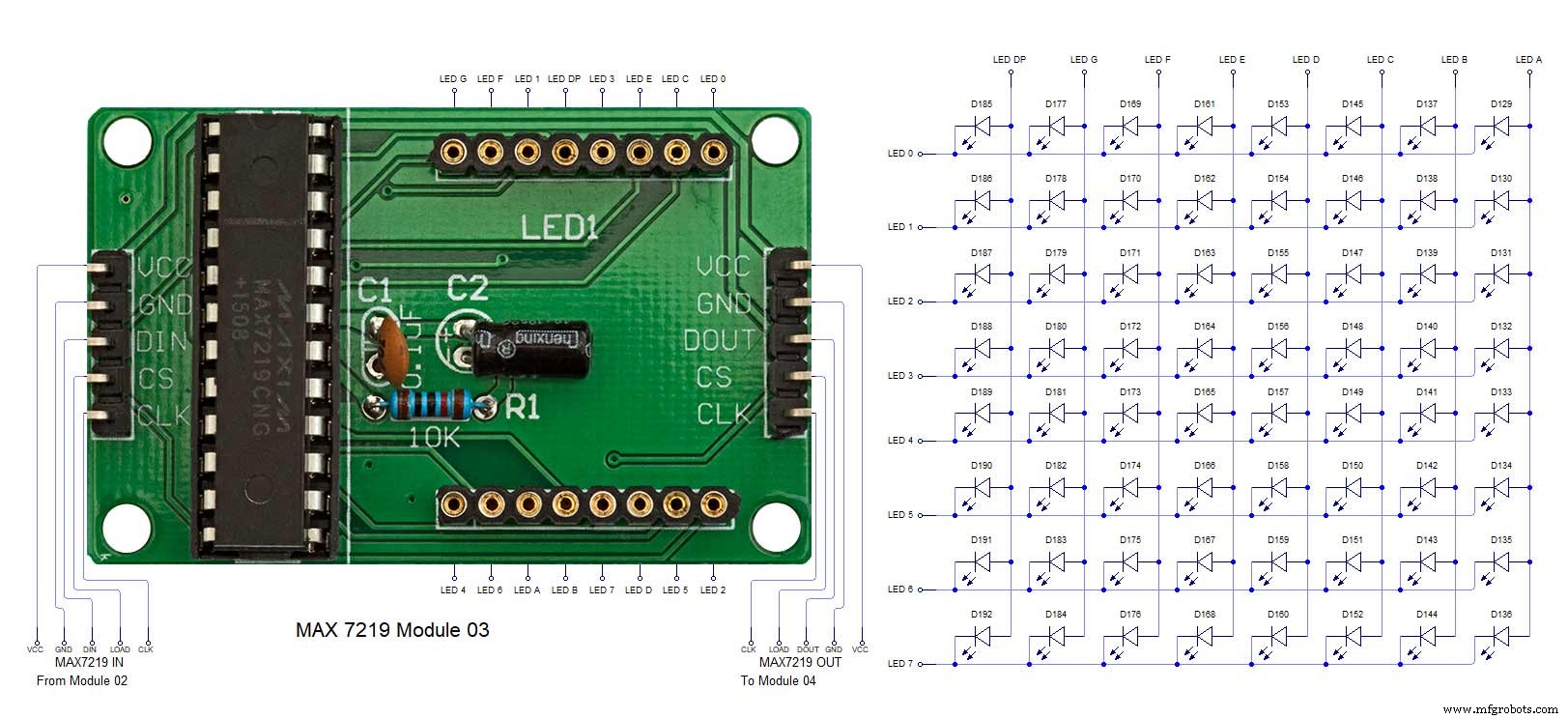 MAX7219 7 segment display module 04 LED connections
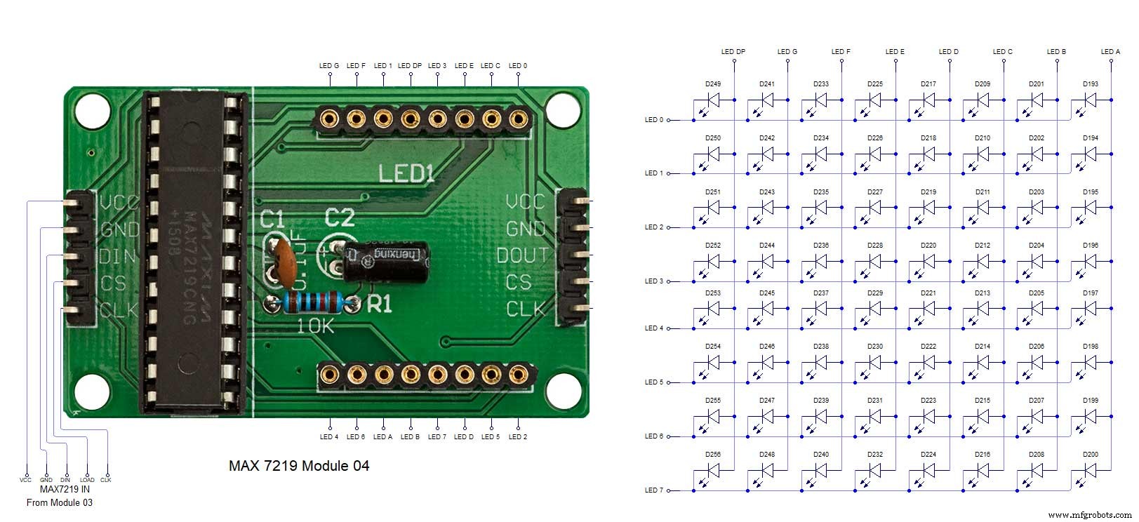
Processus de fabrication
- horloge à coucou
- Impression 3D avec du silicone — son heure arrive-t-elle ?
- Lecture de capteurs analogiques avec une broche GPIO
- horloge IV9 Numitron DIY la plus simple avec Arduino
- Python Timeit() avec des exemples
- Horloge de mots simple (Arduino)
- Horloge Arduino avec heures de prière islamique
- Réduisez les goulots d'étranglement avec 5 outils simples
- Réveil simple avec DS1302 RTC