


Comment créer votre premier clignotant LED FPGA :un didacticiel étape par étape
Guide étape par étape :Création de votre premier clignotant LED FPGA
Partie 1 : Conception de VHDL ou Verilog
Dans ce didacticiel, vous apprendrez à créer du code VHDL et Verilog qui pilote une LED à une fréquence définie par l'utilisateur. Choisissez la langue qui correspond le mieux à votre flux de travail.
Lors de l'écriture HDL, vous devez vérifier que la conception se comporte comme prévu. Les erreurs sont inévitables, la simulation est donc indispensable. Ce didacticiel est divisé en deux phases critiques :
- Conception HDL
- Simulation HDL
Ignorer la simulation peut entraîner un débogage matériel coûteux. Considérez la simulation comme un point de contrôle obligatoire.
Exigences du projet
Écrivez du HDL qui fait clignoter une LED à 100 Hz, 50 Hz, 10 Hz ou 1 Hz avec un rapport cyclique de 50 %. Deux commutateurs sélectionnent la fréquence souhaitée et un LED_EN supplémentaire L'interrupteur doit être haut pour activer la LED. Le FPGA fonctionne sur un oscillateur de 25 MHz.
Table de vérité pour le sélecteur de fréquence :
| Activer | Commutateur1 | Commutateur2 | Fréquence d'entraînement des LED |
|---|---|---|---|
| 0 | – | – | désactivé |
| 1 | 0 | 0 | 100 Hz |
| 1 | 0 | 1 | 50 Hz |
| 1 | 1 | 0 | 10 Hz |
| 1 | 1 | 1 | 1Hz |
Résumé du signal :
| Nom du signal | Direction | Description |
|---|---|---|
| i_clock | Entrée | Horloge à 25 MHz |
| i_enable | Entrée | Activer le commutateur (logic0 =LED éteinte) |
| i_switch_1 | Entrée | Sélecteur de fréquence 1 |
| i_switch_2 | Entrée | Sélecteur de fréquence2 |
| o_led_drive | Sortie | Signal de commande LED |
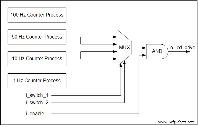
Quatre processus de compteur simultanés surveillent l'horloge de 25 MHz et génèrent des bascules pour chaque fréquence cible. Même lorsqu'une fréquence particulière n'est pas sélectionnée, son compteur continue de fonctionner – un principe fondamental de la concurrence matérielle.
Les commutateurs forment un multiplexeur qui achemine la bascule choisie vers la sortie LED. Les multiplexeurs sont purement logiques combinatoires, ils fonctionnent donc sans horloge.
Vous trouverez ci-dessous un schéma fonctionnel illustrant l'architecture :
Implémentation VHDL
library ieee;
use ieee.std_logic_1164.all;
use ieee.numeric_std.all;
entity tutorial_led_blink is
 port (
 i_clock : in std_logic;
 i_enable : in std_logic;
 i_switch_1 : in std_logic;
 i_switch_2 : in std_logic;
 o_led_drive : out std_logic
 );
end tutorial_led_blink;
architecture rtl of tutorial_led_blink is
 -- Constants to create the frequencies needed:
 -- Formula is: (25 MHz / 100 Hz * 50% duty cycle)
 -- So for 100 Hz: 25,000,000 / 100 * 0.5 = 125,000
 constant c_CNT_100HZ : natural := 125000;
 constant c_CNT_50HZ : natural := 250000;
 constant c_CNT_10HZ : natural := 1250000;
 constant c_CNT_1HZ : natural := 12500000;
 -- These signals will be the counters:
 signal r_CNT_100HZ : natural range 0 to c_CNT_100HZ;
 signal r_CNT_50HZ : natural range 0 to c_CNT_50HZ;
 signal r_CNT_10HZ : natural range 0 to c_CNT_10HZ;
 signal r_CNT_1HZ : natural range 0 to c_CNT_1HZ;

 -- These signals will toggle at the frequencies needed:
 signal r_TOGGLE_100HZ : std_logic := '0';
 signal r_TOGGLE_50HZ : std_logic := '0';
 signal r_TOGGLE_10HZ : std_logic := '0';
 signal r_TOGGLE_1HZ : std_logic := '0';
 -- One bit select wire.
 signal w_LED_SELECT : std_logic;

begin
 -- All processes toggle a specific signal at a different frequency.
 -- They all run continuously even if the switches are
 -- not selecting their particular output.

 p_100_HZ : process (i_clock) is
 begin
 if rising_edge(i_clock) then
 if r_CNT_100HZ = c_CNT_100HZ-1 then -- -1, since counter starts at 0
 r_TOGGLE_100HZ <= not r_TOGGLE_100HZ;
 r_CNT_100HZ <= 0;
 else
 r_CNT_100HZ <= r_CNT_100HZ + 1;
 end if;
 end if;
 end process p_100_HZ;
 p_50_HZ : process (i_clock) is
 begin
 if rising_edge(i_clock) then
 if r_CNT_50HZ = c_CNT_50HZ-1 then -- -1, since counter starts at 0
 r_TOGGLE_50HZ <= not r_TOGGLE_50HZ;
 r_CNT_50HZ <= 0;
 else
 r_CNT_50HZ <= r_CNT_50HZ + 1;
 end if;
 end if;
 end process p_50_HZ;

 p_10_HZ : process (i_clock) is
 begin
 if rising_edge(i_clock) then
 if r_CNT_10HZ = c_CNT_10HZ-1 then -- -1, since counter starts at 0
 r_TOGGLE_10HZ <= not r_TOGGLE_10HZ;
 r_CNT_10HZ <= 0;
 else
 r_CNT_10HZ <= r_CNT_10HZ + 1;
 end if;
 end if;
 end process p_10_HZ;

 p_1_HZ : process (i_clock) is
 begin
 if rising_edge(i_clock) then
 if r_CNT_1HZ = c_CNT_1HZ-1 then -- -1, since counter starts at 0
 r_TOGGLE_1HZ <= not r_TOGGLE_1HZ;
 r_CNT_1HZ <= 0;
 else
 r_CNT_1HZ <= r_CNT_1HZ + 1;
 end if;
 end if;
 end process p_1_HZ;

 -- Create a multiplexor based on switch inputs
 w_LED_SELECT <= r_TOGGLE_100HZ when (i_switch_1 = '0' and i_switch_2 = '0') else
 r_TOGGLE_50HZ when (i_switch_1 = '0' and i_switch_2 = '1') else
 r_TOGGLE_10HZ when (i_switch_1 = '1' and i_switch_2 = '0') else
 r_TOGGLE_1HZ;

 -- Only allow o_led_drive to drive when i_enable is high (and gate).
 o_led_drive <= w_LED_SELECT and i_enable;
end rtl;
Implémentation Verilog
module tutorial_led_blink
(
 i_clock,
 i_enable,
 i_switch_1,
 i_switch_2,
 o_led_drive
 );
 input i_clock;
 input i_enable;
 input i_switch_1;
 input i_switch_2;
 output o_led_drive;

 // Constants (parameters) to create the frequencies needed:
 // Input clock is 25 kHz, chosen arbitrarily.
 // Formula is: (25 kHz / 100 Hz * 50% duty cycle)
 // So for 100 Hz: 25,000 / 100 * 0.5 = 125
 parameter c_CNT_100HZ = 125;
 parameter c_CNT_50HZ = 250;
 parameter c_CNT_10HZ = 1250;
 parameter c_CNT_1HZ = 12500;
 // These signals will be the counters:
 reg [31:0] r_CNT_100HZ = 0;
 reg [31:0] r_CNT_50HZ = 0;
 reg [31:0] r_CNT_10HZ = 0;
 reg [31:0] r_CNT_1HZ = 0;

 // These signals will toggle at the frequencies needed:
 reg r_TOGGLE_100HZ = 1'b0;
 reg r_TOGGLE_50HZ = 1'b0;
 reg r_TOGGLE_10HZ = 1'b0;
 reg r_TOGGLE_1HZ = 1'b0;

 // One bit select
 reg r_LED_SELECT;
 wire w_LED_SELECT;


begin
 // All always blocks toggle a specific signal at a different frequency.
 // They all run continuously even if the switches are
 // not selecting their particular output.
 always @ (posedge i_clock)
 begin
 if (r_CNT_100HZ == c_CNT_100HZ-1) // -1, since counter starts at 0
 begin
 r_TOGGLE_100HZ <= !r_TOGGLE_100HZ;
 r_CNT_100HZ <= 0;
 end
 else
 r_CNT_100HZ <= r_CNT_100HZ + 1;
 end

 always @ (posedge i_clock)
 begin
 if (r_CNT_50HZ == c_CNT_50HZ-1) // -1, since counter starts at 0
 begin
 r_TOGGLE_50HZ <= !r_TOGGLE_50HZ;
 r_CNT_50HZ <= 0;
 end
 else
 r_CNT_50HZ <= r_CNT_50HZ + 1;
 end
 always @ (posedge i_clock)
 begin
 if (r_CNT_10HZ == c_CNT_10HZ-1) // -1, since counter starts at 0
 begin
 r_TOGGLE_10HZ <= !r_TOGGLE_10HZ;
 r_CNT_10HZ <= 0;
 end
 else
 r_CNT_10HZ <= r_CNT_10HZ + 1;
 end

 always @ (posedge i_clock)
 begin
 if (r_CNT_1HZ == c_CNT_1HZ-1) // -1, since counter starts at 0
 begin
 r_TOGGLE_1HZ <= !r_TOGGLE_1HZ;
 r_CNT_1HZ <= 0;
 end
 else
 r_CNT_1HZ <= r_CNT_1HZ + 1;
 end
 // Create a multiplexer based on switch inputs
 always @ (*)
 begin
 case () // Concatenation Operator
 2'b11 : r_LED_SELECT <= r_TOGGLE_1HZ;
 2'b10 : r_LED_SELECT <= r_TOGGLE_10HZ;
 2'b01 : r_LED_SELECT <= r_TOGGLE_50HZ;
 2'b00 : r_LED_SELECT <= r_TOGGLE_100HZ;
 endcase
 end
 assign o_led_drive = r_LED_SELECT & i_enable;
 // Alternative way to design multiplexer (same as above):
 // More compact, but harder to read, especially to those new to Verilog
 // assign w_LED_SELECT = i_switch_1 ? (i_switch_2 ? r_TOGGLE_1HZ : r_TOGGLE_10HZ) :
 //(i_switch_2 ? r_TOGGLE_50HZ : r_TOGGLE_100HZ);
 // assign o_led_drive = w_LED_SELECT & i_enable;


end

endmodule
Étape suivante :Simulez cette conception en VHDL ou Verilog pour confirmer le comportement correct avant le déploiement.
VHDL
- Comment utiliser Wait On et Wait Until en VHDL
- Comment utiliser les instructions conditionnelles en VHDL :If-Then-Elsif-Else
- Comment utiliser une procédure dans un processus en VHDL
- Guide du débutant sur l'utilisation de Modelsim pour la simulation FPGA et ASIC
- Tutoriel :Votre premier programme FPGA :un clignotant LED
- Quiz VHDL de base – partie 2
- Comment créer un banc d'essai d'auto-vérification
- Exemples de conversions VHDL
- Master VHDL :introduction complète à la conception de FPGA et d'ASIC