



Horloge LED à horloge temps réel Arduino : Construire un affichage horaire fiable
Composants et fournitures
| Arduino UNO | × | 1 |
| Module RTC (Horloge temps réel) | × | 1 |
| Résistance 1 kΩ | × | 15 |
| Résistance traversante 120 Ω | × | 15 |
| Régulateur linéaire 7805 | × | 1 |
| Condensateur 22 pF | × | 1 |
| Quartz 16 MHz | × | 1 |
| Condensateur 10 µF | × | 1 |
| Pile bouton CR2032 | × | 1 |
| Support pile CR2032 | × | 1 |
| LED 5 mm verte | × | 190 |
| Transistor bipolaire RF NPN | × | 10 |
| Transistor PNP usage général | × | 12 |
| Interrupteur tactile à action supérieure | × | 4 |
| Alimentation 12V 5A (60W) | × | 1 |
Outils et machines nécessaires
- Fer à souder (générique)
- Fil à souder sans plomb
- Multimètre numérique autorange
À propos de ce projet
Vous devez d'abord télécharger les bibliothèques suivantes (liens en fin de page) :
- Wire.h
- RTClib.h
Liste des pièces
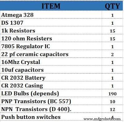
Regarder la vidéo
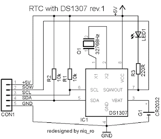
Voici le module horloge RTC
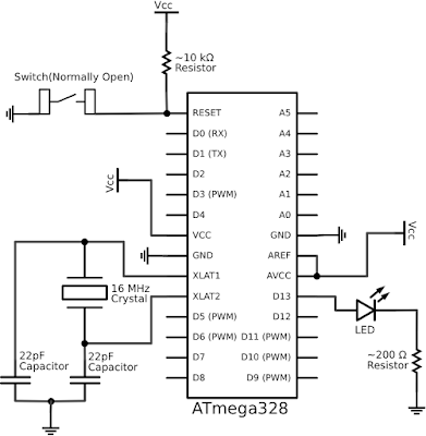
Voici le circuit Arduino
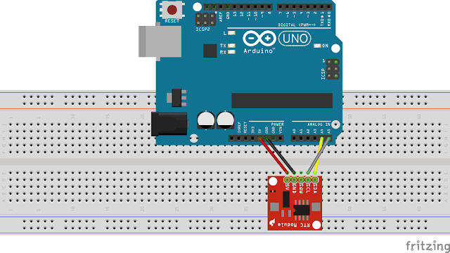
Connexions de câblage RTC
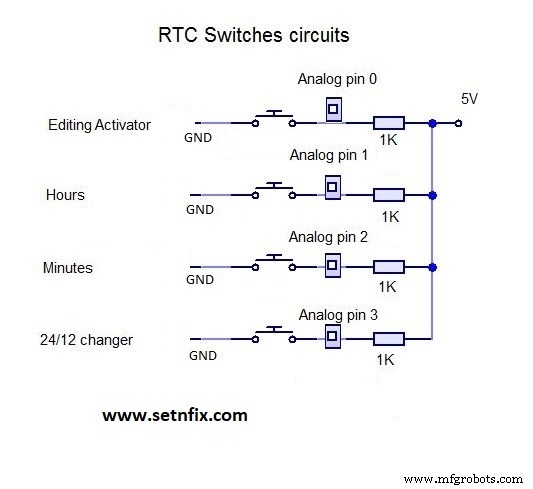
Commutateurs RTC
Identifier anode et cathode
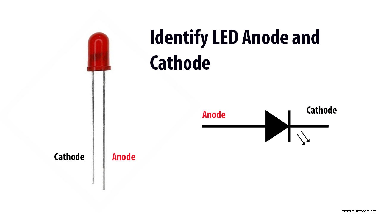
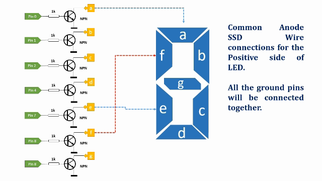
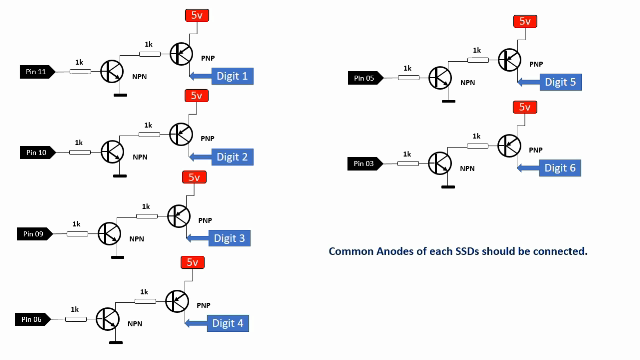
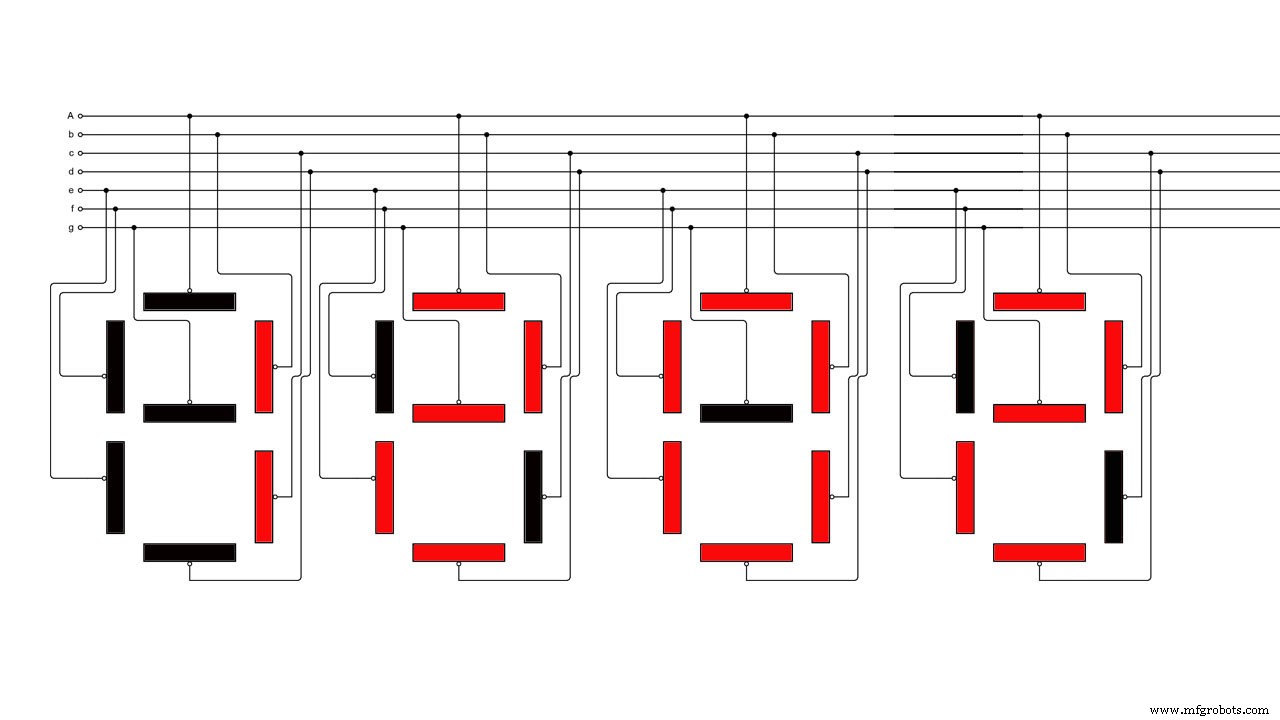
Schéma de circuit (ANODE COMMUNE)
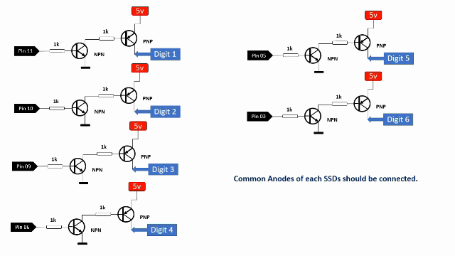
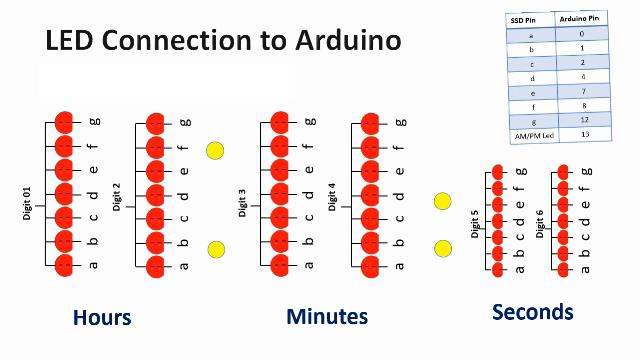
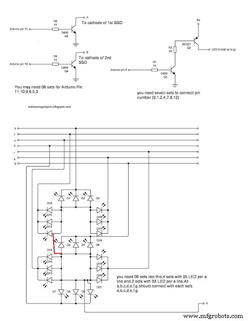
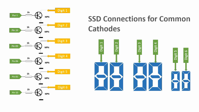
SI VOUS UTILISEZ DES LED CATHODE COMMUNE, FAITES LES MODIFICATIONS SUIVANTES
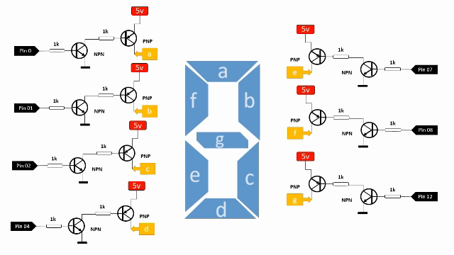
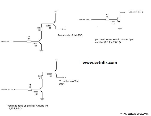
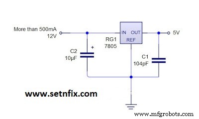
ALIMENTATION
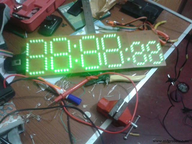
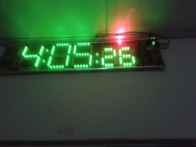
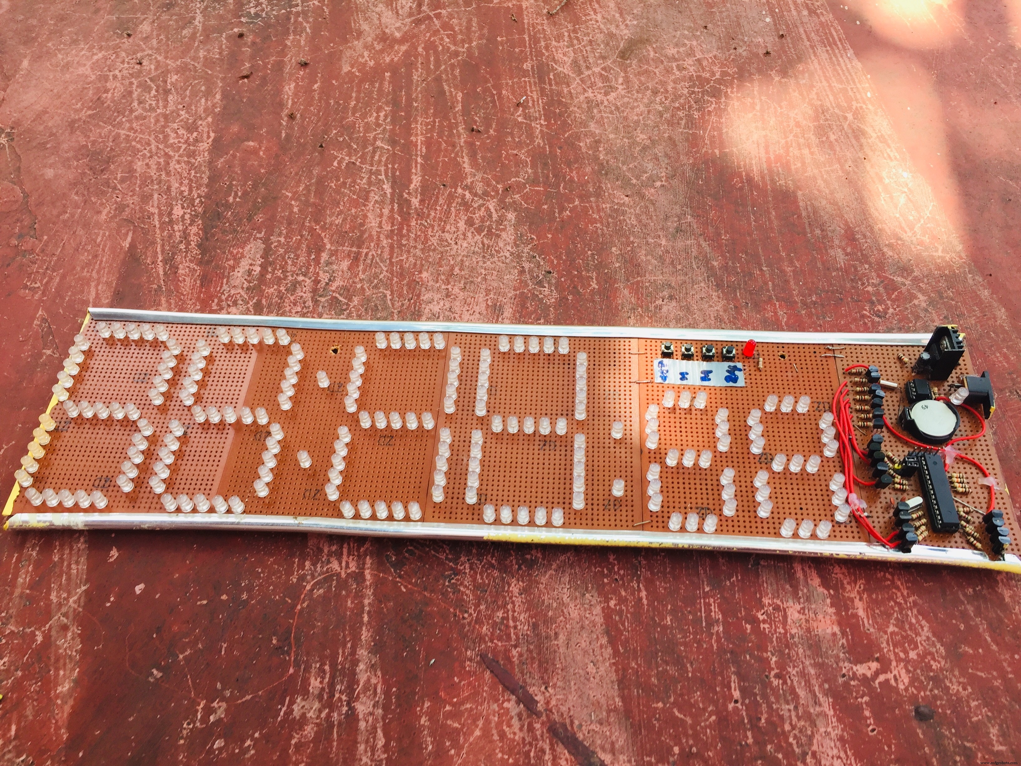
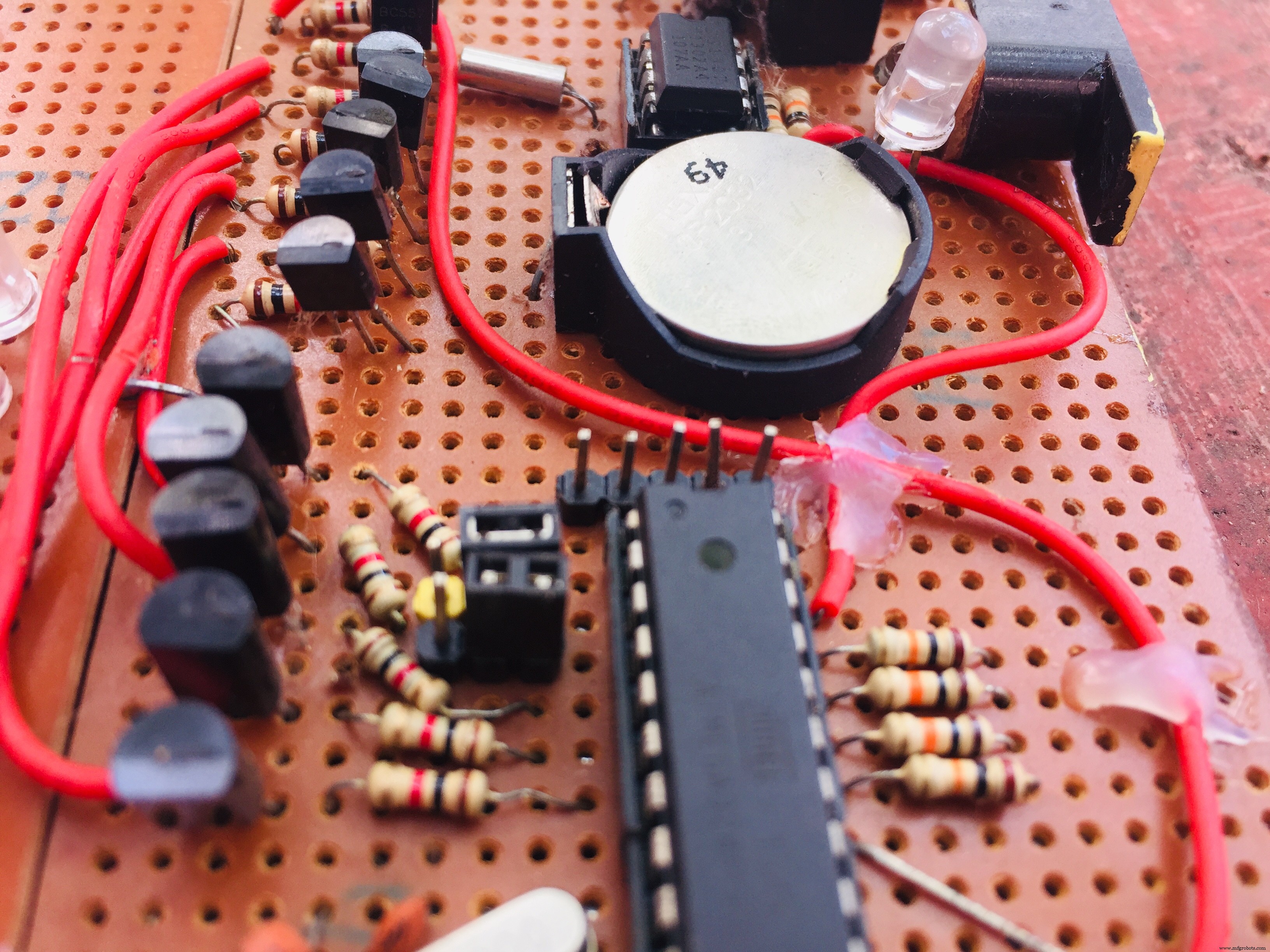
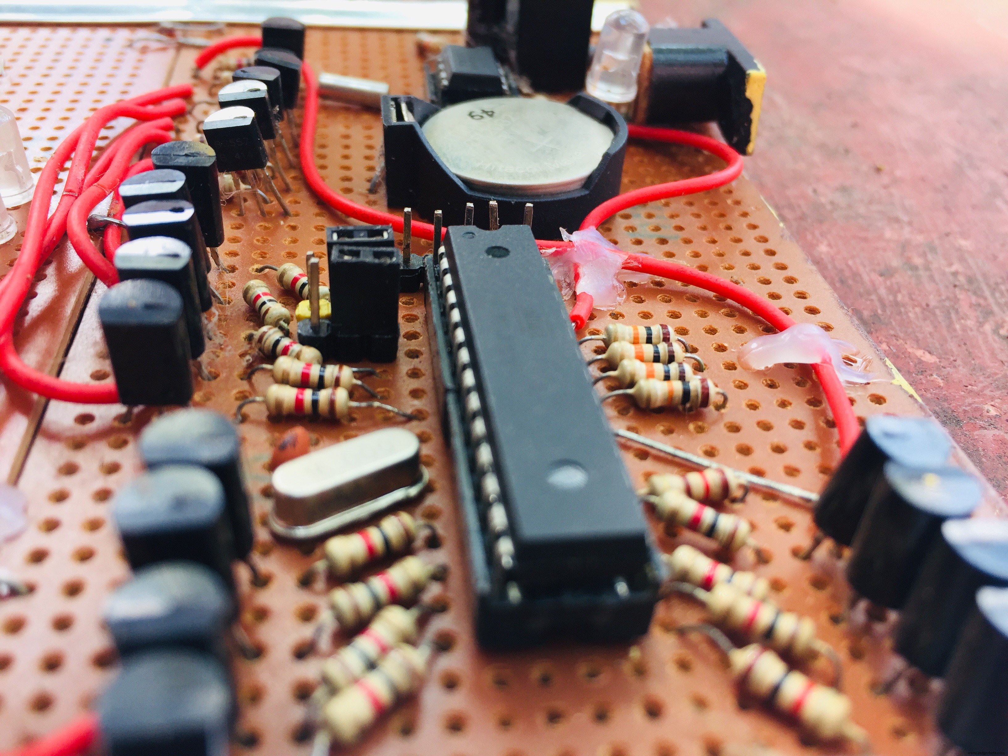
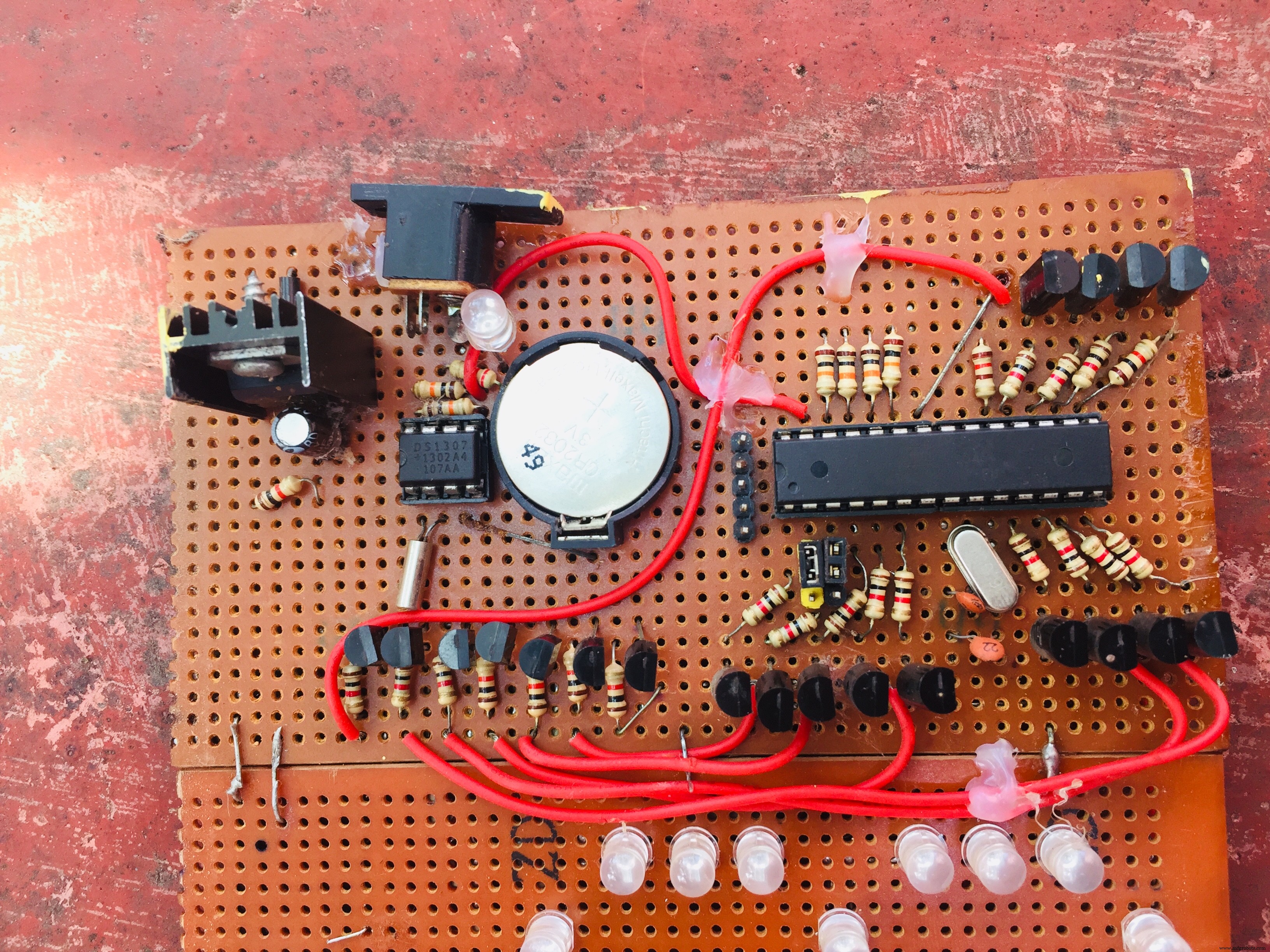
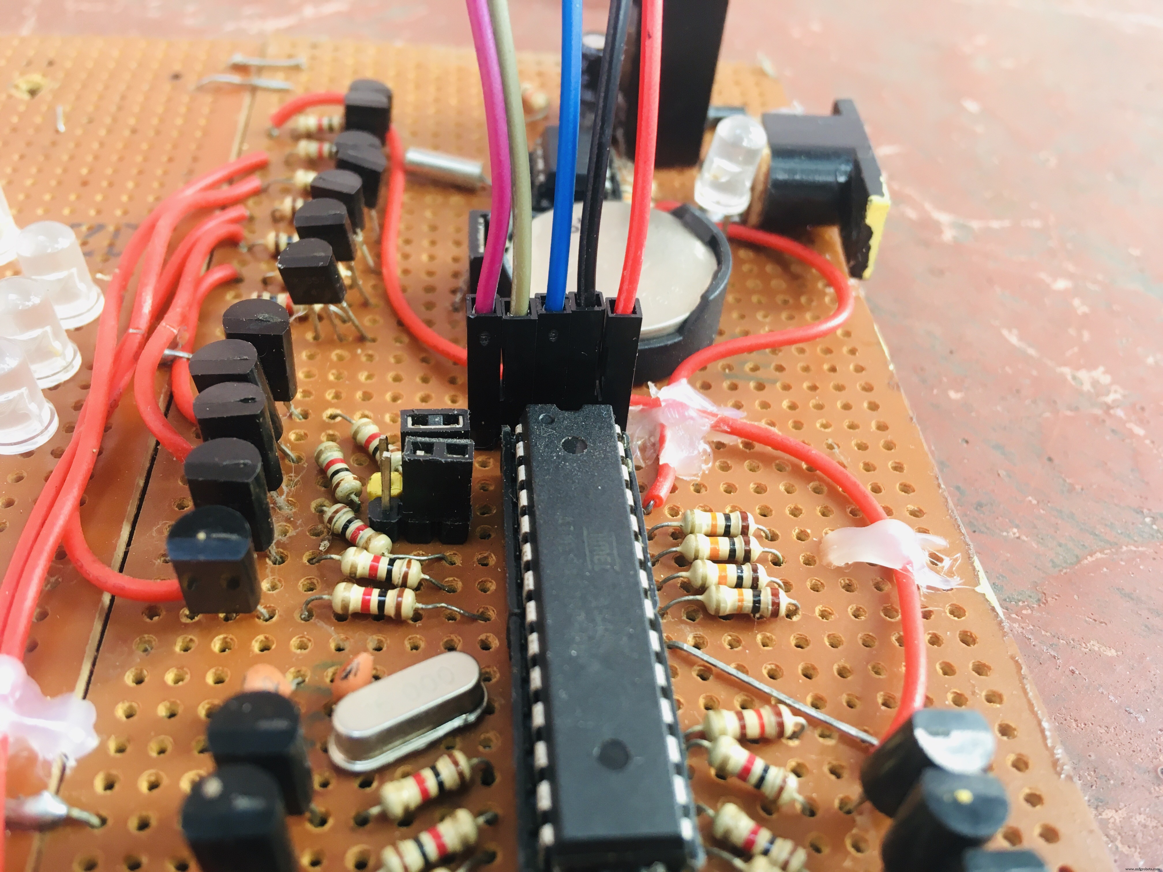
Code
Codes horloge LED Arduino
/* 4 digits 7 segments : https://www.sparkfun.com/products/9483 Datasheet : https://www.sparkfun.com/datasheets/Components/LED/7-Segment/YSD-439AR6B-35.pdf */ // Connexion modifiée par niq_ro depuis https://nicuflorica.blogspot.com // Datasheet : https://www.tme.eu/ro/Document/dfc2efde2e22005fd28615e298ea2655/KW4-563XSA.pdf // Code modifié par BMIAK Basnayaka // https://www.setnfix.com int digit1 = 11; int digit2 = 10; int digit3 = 9; int digit4 = 6; int digit5 = 5; int digit6 = 3; int segA = 0; int segB = 1; int segC = 2; int segD = 4; int segE = 7; int segF = 8; int segG = 12; int segDP = 13; #include#include "RTClib.h" RTC_DS1307 RTC; byte SW0 = A0; byte SW1 = A2; byte SW2 = A1; byte SWT = A3; int Adhr=0, Admnt=0, D=0, Z=0; long zh, uh, ore; long zm, um, miniti; void setup() { Wire.begin(); RTC.begin(); // RTC.adjust(DateTime(F(__DATE__), F(__TIME__))); // Décommenter pour régler l'heure // Configuration sortie SQW 1Hz Wire.beginTransmission(0x68); Wire.write(0x07); Wire.write(0x10); Wire.endTransmission(); pinMode(segA, OUTPUT); pinMode(segB, OUTPUT); pinMode(segC, OUTPUT); pinMode(segD, OUTPUT); pinMode(segE, OUTPUT); pinMode(segF, OUTPUT); pinMode(segG, OUTPUT); pinMode(segDP, OUTPUT); pinMode(digit1, OUTPUT); pinMode(digit2, OUTPUT); pinMode(digit3, OUTPUT); pinMode(digit4, OUTPUT); pinMode(digit5, OUTPUT); pinMode(digit6, OUTPUT); pinMode(SW0, INPUT); pinMode(SW1, INPUT); pinMode(SW2, INPUT); pinMode(SWT, INPUT); digitalWrite(SW0, HIGH); digitalWrite(SW1, HIGH); digitalWrite(SW2, HIGH); digitalWrite(segDP, LOW); } void loop() { DateTime now = RTC.now(); long HR = now.hour()*1000; long timp = (HR*10)+now.minute()*100+now.second(); Adhr = now.hour(); Admnt = now.minute(); int DIM = 0; if (timp >= 250000) timp = timp - 240000; // Commutation 12/24h if (timp < 130000) digitalWrite(segDP, LOW); if (digitalRead(SWT)==0) { delay(300); D = (D==0)?1:0; } if (D == 0) { if (timp >= 130000) { timp -= 120000; digitalWrite(segDP, HIGH); } } if (timp >= 130000) digitalWrite(segDP, LOW); if ((D==1) && (timp < 130000)) digitalWrite(segDP, LOW); for(int i=100; i>0; i--) { if (timp >= 100000) displayNumber01(timp); else displayNumber02(timp); } for(int i=100; i>0; i--) { if (timp >= 100000) displayNumber03(timp); else displayNumber04(timp); } for(int i=100; i>0; i--) { if (timp >= 100000) displayNumber05(timp); else displayNumber06(timp); } if (digitalRead(SW0)==0) { delay(100); Z=1; set_time(); } } void set_time() { byte minutes=Admnt, hours=Adhr; if ((hours & 0x0f) > 9) hours += 6; if (hours > 0x24) hours = 1; if ((minutes & 0x0f) > 9) minutes += 6; if (minutes > 0x59) minutes = 0; while (Z) { int TST = digitalRead(SW2); while (TST==0) { // Régler heures hours++; zh = hours/16; uh = hours - 16*zh; ore = 10*zh + uh; zm = minutes/16; um = minutes - 16*zm; miniti = 10*zm + um; if ((hours & 0x0f) > 9) hours += 6; if (hours > 0x24) hours = 1; for(int i=400; i>0; i--) displayNumber01(ore*10000+miniti*100); TST = digitalRead(SW2); } while (digitalRead(SW1)==0) { // Régler minutes minutes++; zh = hours/16; uh = hours - 16*zh; ore = 10*zh + uh; zm = minutes/16; um = minutes - 16*zm; miniti = 10*zm + um; for(int i=400; i>0; i--) displayNumber01(ore*10000+miniti*100); if ((minutes & 0x0f) > 9) minutes += 6; if (minutes > 0x59) minutes = 0; } // Écriture dans RTC Wire.beginTransmission(0x68); Wire.write(0); Wire.write(0x00); Wire.write(minutes); Wire.write(0x80 | hours); Wire.write(0x06); Wire.write(0x01); Wire.write(0x05); Wire.write(0x09); Wire.write(0x10); Wire.endTransmission(); for(int i=400; i>0; i--) displayNumber01(ore*10000+miniti*100); delay(100); if (digitalRead(SW0)==0) Z = 0; delay(300); } } // Fonctions d'affichage multiplexé (displayNumber01 à displayNumber06) et lightNumber // ... (code complet disponible dans le fichier source)
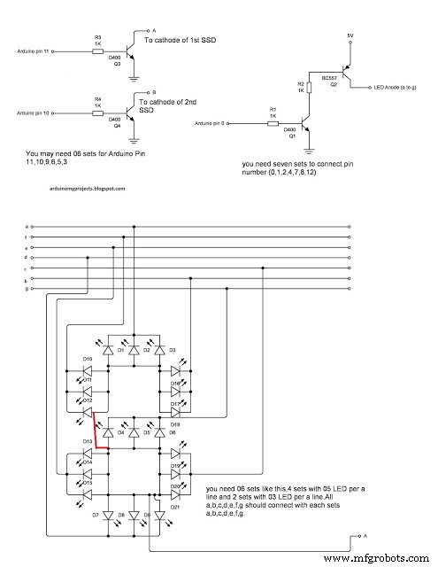
Schéma
Câblage de l'afficheur 7 segments avec LED.
Support caméra FPV biaxe DIY : Tutoriel joystick contrôlé par Arduino
Système de stationnement intelligent : Solutions de stationnement urbain efficaces
Processus de fabrication
- Horloge POV Arduino : Construire un affichage LED à persistance rétinienne
- Horloge à Mots DIY Arduino – Afficheur Temps Réel Élégant et Personnalisable
- Construire un oscilloscope Arduino 20 kHz sur écran Nokia 5110 – Guide DIY facile
- Construire une horloge maître LED personnalisée avec alarme – Visible à 12 mètres
- Stores intelligents : contrôle automatisé de la lumière avec Arduino et énergie solaire
- Horloge à Mots Italienne avec Arduino Nano, NeoPixel, LCD et RTC
- Contrôler une LED par Bluetooth avec Arduino et MIT App Inventor
- Construire un robot quadrupède Arduino intelligent : guide étape par étape
- Circuit d'entrée analogique isolée pour Arduino : Protection contre les parasites industriels