


Contrôle sans fil de voiture robot Arduino utilisant les modules émetteurs-récepteurs Bluetooth HC-05, NRF24L01 et HC-12
Dans ce tutoriel, nous allons apprendre à contrôler sans fil la voiture robot Arduino que nous avons réalisée dans la vidéo précédente. Je vais vous montrer trois méthodes différentes de contrôle sans fil, en utilisant le module Bluetooth HC-05, le module émetteur-récepteur NRF24L01 et le module sans fil longue portée HC-12, ainsi qu'en utilisant un Smartphone et une application Android sur mesure. Vous pouvez regarder la vidéo suivante ou lire le didacticiel écrit ci-dessous pour plus de détails.
J'ai déjà des tutoriels sur la façon de connecter et d'utiliser chacun de ces modules avec la carte Arduino, donc si vous avez besoin de plus de détails, vous pouvez toujours les consulter. Les liens vers chacun d'eux se trouvent ci-dessous dans l'article.
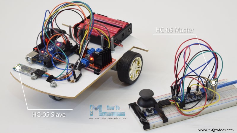
Nous allons commencer par la communication Bluetooth, et pour cela nous avons besoin de deux modules Bluetooth HC-05 qui doivent être configurés comme appareils maître et esclave.
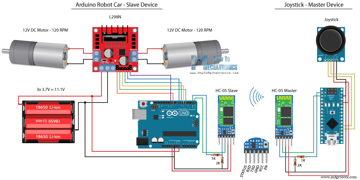
Nous pouvons facilement le faire en utilisant les commandes AT, et j'ai défini le joystick comme maître et la voiture robot Arduino comme esclave. Voici le schéma de circuit complet pour cet exemple :
Vous pouvez obtenir les composants nécessaires pour cet exemple à partir des liens ci-dessous :
Nous utiliserons le même code du tutoriel précédent, où nous contrôlons la voiture robot Arduino directement à l'aide du joystick, et nous y apporterons quelques modifications.
Code maître HC-05 :
Le code au niveau de l'appareil maître, ou du joystick est assez simple. Il suffit de lire les valeurs X et Y du joystick, qui régulent en fait la vitesse des moteurs, et de les envoyer via le port série au périphérique Bluetooth HC-05 esclave. On peut noter ici que les valeurs analogiques du joystick de 0 à 1023 sont converties en valeurs a de 0 à 255 en les plongeant par 4.
Nous faisons cela parce que cette plage, de 0 à 255, peut être envoyée, sur le périphérique Bluetooth, comme 1 octet qui est plus facile à accepter de l'autre côté, ou à la voiture robot Arduino.
Donc ici, si la série a reçu les 2 octets, les valeurs X et Y, en utilisant la fonction Serial.read() nous lirons les deux.
Il ne nous reste plus qu'à reconvertir les valeurs dans la plage de 0 à 1023, adaptée au code de contrôle moteur ci-dessous, dont nous avons déjà expliqué le fonctionnement dans la vidéo précédente.
Juste une note rapide que lors du téléchargement du code, nous devons déconnecter les broches RX et TX de la carte Arduino.
Code esclave HC-05 complet :
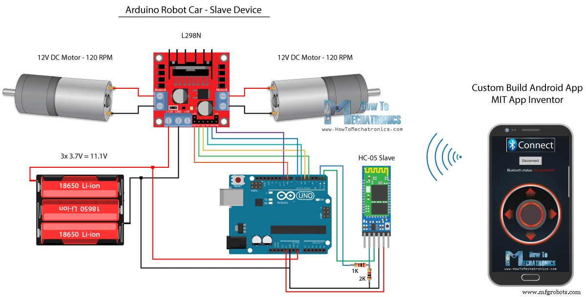
Voyons ensuite comment nous pouvons contrôler notre voiture robot Arduino à l'aide d'une application Android personnalisée. Le schéma du circuit de la voiture robot est exactement le même que dans l'exemple précédent, avec le mode Bluetooth HC-05 défini comme appareil esclave.
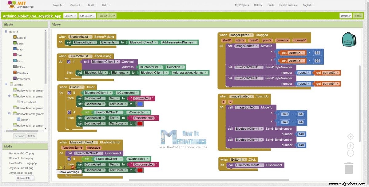
D'autre part, en utilisant l'application en ligne MIT App Inventor, nous allons créer notre propre application Android, et voici à quoi cela ressemble.
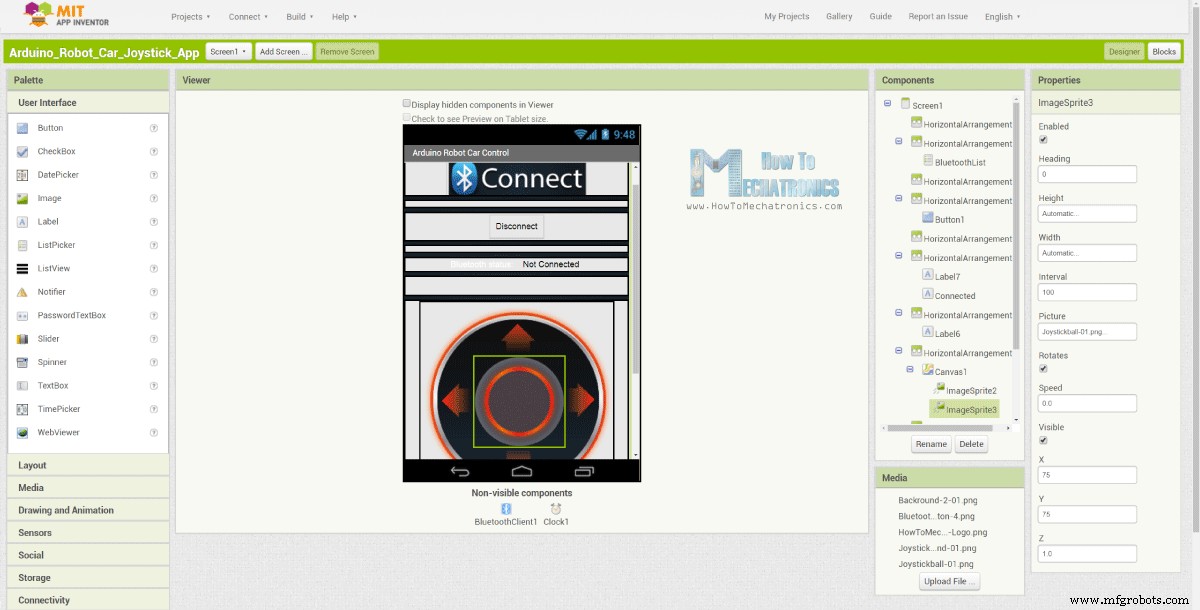
Donc, fondamentalement, l'application simule un joystick, dont l'apparence est constituée de deux images, ou sprites d'image.
Si nous jetons un coup d'œil aux blocs de cette application, nous pouvons voir que lorsque le sprite du joystick est déplacé, l'image de la balle du joystick est déplacée vers l'emplacement actuel de notre doigt, et en même temps nous envoyons le X et Y valeurs via le Bluetooth vers la voiture Arduino.
Ces valeurs sont acceptées par l'Arduino de la même manière que dans l'exemple précédent, en utilisant la fonction Serial.read.
Ce que nous devons faire en plus ici, c'est convertir les valeurs X et Y reçues du smartphone dans la plage de 0 à 1023, adaptée au code de commande de moteur ci-dessous. Ces valeurs dépendent de la taille du canevas, et les valeurs X et Y que j'obtenais de mon application étaient de 60 à 220, ce qui, en utilisant la fonction map(), je les ai facilement converties.
Au niveau des blocs d'application, nous pouvons également voir que lorsque le sprite d'image est retouché, la boule du joystick revient au centre de la toile et les valeurs appropriées sont envoyées à la voiture pour qu'elle s'arrête de bouger. Vous pouvez trouver et télécharger cette application sur l'article du site Web, ainsi que les deux images du joystick afin que vous puissiez créer la vôtre ou modifier cette application.
Vous pouvez télécharger l'application Android ci-dessous, ainsi que les deux images du joystick :
Code Arduino complet :
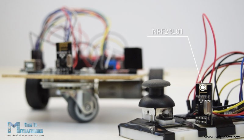
Nous pouvons maintenant passer à la méthode suivante, le contrôle sans fil de la voiture robot Arduino à l'aide des modules émetteurs-récepteurs NRF24L01.
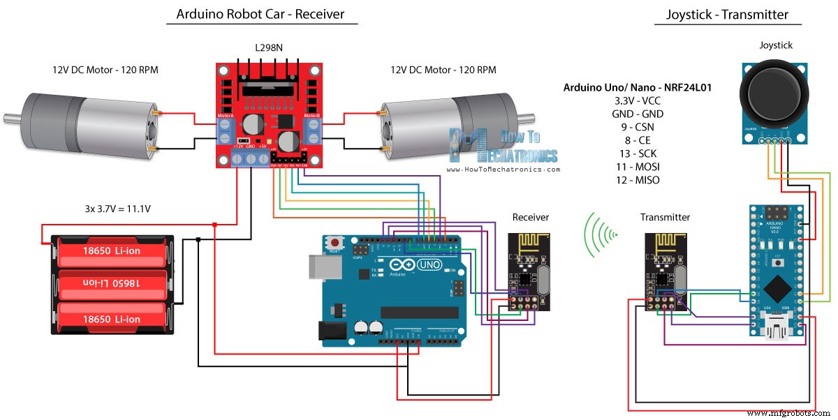
Voici le schéma du circuit. On peut noter que ces modules utilisent la communication SPI, donc par rapport à l'exemple précédent, j'ai dû déplacer les broches Enable A et Enable B du driver L298N vers les broches numéro 2 et 3 de la carte Arduino. Vous pouvez obtenir le NRF24L01 module sur le lien Amazon suivant.
Pour cet exemple, nous devons installer la bibliothèque RF24. De la même manière que dans l'exemple précédent, après avoir défini certaines broches et configuré le module en tant qu'émetteur, nous lisons les valeurs X et Y du joystick et les envoyons à l'autre module NRF24L01 de la voiture robot Arduino.
Tout d'abord, nous pouvons noter que les lectures analogiques sont des chaînes, qui, à l'aide de la fonction string.toCharArray(), sont placées dans un tableau de caractères. Ensuite, en utilisant la fonction radio.write(), nous envoyons ces données de tableau de caractères à l'autre module.
Code émetteur :
D'un autre côté. sur la voiture robot Arduino, après avoir défini le module comme récepteur, nous acceptons les données à l'aide de la fonction radio.read(). Ensuite, en utilisant la fonction atoi(), nous convertissons les données reçues, ou les valeurs X et Y du joystick, en valeurs entières, qui conviennent au code de contrôle moteur ci-dessous.
C'est aussi simple que cela, mais bien sûr, comme je l'ai déjà dit, si vous avez besoin de plus de détails sur la connexion et la configuration des modules, vous pouvez toujours consulter mon tutoriel particulier.
Code du destinataire :
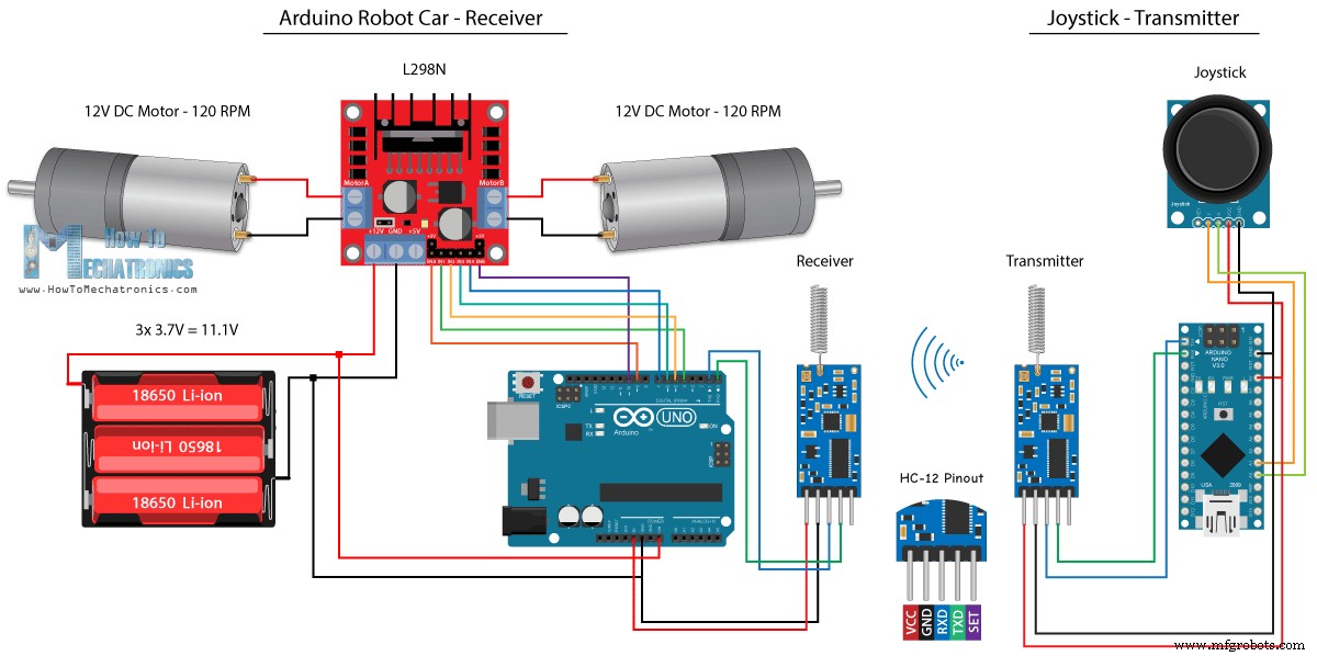
Pour la dernière méthode de contrôle sans fil de la voiture robot Arduino, nous utiliserons les modules émetteurs-récepteurs longue portée HC-12. Ces modules peuvent communiquer entre eux à des distances allant jusqu'à 1,8 km.
Le schéma de circuit de cet exemple est presque le même que celui des modules Bluetooth HC-05, car ils utilisent la même méthode de communication avec l'Arduino, via le port série.
Vous pouvez obtenir le module émetteur-récepteur HC-12 sur le lien Amazon suivant.
Le code du Joystick est exactement le même que celui de la communication Bluetooth. Nous lisons simplement les valeurs analogiques du joystick et les envoyons à l'autre module à l'aide de la fonction Serial.write().
Code émetteur :
De l'autre côté, avec la boucle while(), nous attendons que les données arrivent, puis les lisons à l'aide de la fonction Serial.read() et les reconvertissons dans la plage de 0 à 1023, adaptée au code de contrôle moteur ci-dessous.
Code récepteur :
C'est donc à peu près tout pour ce tutoriel. N'hésitez pas à poser des questions dans la section des commentaires ci-dessous.Contrôle de voiture robot Arduino à l'aide du module Bluetooth HC-05
Code source
/*
   Arduino Robot Car Wireless Control using the HC-05 Bluetooth

                == MASTER DEVICE - Joystick ==

   by Dejan Nedelkovski, www.HowToMechatronics.com
*/

int xAxis, yAxis;

void setup() {
  Serial.begin(38400); // Default communication rate of the Bluetooth module
}

void loop() {
  xAxis = analogRead(A0); // Read Joysticks X-axis
  yAxis = analogRead(A1); // Read Joysticks Y-axis

  // Send the values via the serial port to the slave HC-05 Bluetooth device
  Serial.write(xAxis/4); // Dividing by 4 for converting from 0 - 1023 to 0 - 256, (1 byte) range
  Serial.write(yAxis/4);
  delay(20);
}Code language: Arduino (arduino)// Code from the Arduino Robot Car
// Read the incoming data from the Joystick, or the master Bluetooth device
while (Serial.available() >= 2) {
x = Serial.read();
delay(10);
y = Serial.read();
}Code language: Arduino (arduino)// Code from the Arduino Robot Car
// Convert back the 0 - 255 range to 0 - 1023, suitable for motor control code below
xAxis = x*4;
yAxis = y*4;Code language: Arduino (arduino)/*
Arduino Robot Car Wireless Control using the HC-05 Bluetooth
== SLAVE DEVICE - Arduino robot car ==
by Dejan Nedelkovski, www.HowToMechatronics.com
*/
#define enA 9
#define in1 4
#define in2 5
#define enB 10
#define in3 6
#define in4 7
int xAxis, yAxis;
unsigned int x = 0;
unsigned int y = 0;
int motorSpeedA = 0;
int motorSpeedB = 0;
void setup() {
pinMode(enA, OUTPUT);
pinMode(enB, OUTPUT);
pinMode(in1, OUTPUT);
pinMode(in2, OUTPUT);
pinMode(in3, OUTPUT);
pinMode(in4, OUTPUT);
Serial.begin(38400); // Default communication rate of the Bluetooth module
}
void loop() {
// Default value - no movement when the Joystick stays in the center
x = 510 / 4;
y = 510 / 4;
// Read the incoming data from the Joystick, or the master Bluetooth device
while (Serial.available() >= 2) {
x = Serial.read();
delay(10);
y = Serial.read();
}
delay(10);
// Convert back the 0 - 255 range to 0 - 1023, suitable for motor control code below
xAxis = x*4;
yAxis = y*4;
// Y-axis used for forward and backward control
if (yAxis < 470) {
// Set Motor A backward
digitalWrite(in1, HIGH);
digitalWrite(in2, LOW);
// Set Motor B backward
digitalWrite(in3, HIGH);
digitalWrite(in4, LOW);
// Convert the declining Y-axis readings for going backward from 470 to 0 into 0 to 255 value for the PWM signal for increasing the motor speed
motorSpeedA = map(yAxis, 470, 0, 0, 255);
motorSpeedB = map(yAxis, 470, 0, 0, 255);
}
else if (yAxis > 550) {
// Set Motor A forward
digitalWrite(in1, LOW);
digitalWrite(in2, HIGH);
// Set Motor B forward
digitalWrite(in3, LOW);
digitalWrite(in4, HIGH);
// Convert the increasing Y-axis readings for going forward from 550 to 1023 into 0 to 255 value for the PWM signal for increasing the motor speed
motorSpeedA = map(yAxis, 550, 1023, 0, 255);
motorSpeedB = map(yAxis, 550, 1023, 0, 255);
}
// If joystick stays in middle the motors are not moving
else {
motorSpeedA = 0;
motorSpeedB = 0;
}
// X-axis used for left and right control
if (xAxis < 470) {
// Convert the declining X-axis readings from 470 to 0 into increasing 0 to 255 value
int xMapped = map(xAxis, 470, 0, 0, 255);
// Move to left - decrease left motor speed, increase right motor speed
motorSpeedA = motorSpeedA - xMapped;
motorSpeedB = motorSpeedB + xMapped;
// Confine the range from 0 to 255
if (motorSpeedA < 0) {
motorSpeedA = 0;
}
if (motorSpeedB > 255) {
motorSpeedB = 255;
}
}
if (xAxis > 550) {
// Convert the increasing X-axis readings from 550 to 1023 into 0 to 255 value
int xMapped = map(xAxis, 550, 1023, 0, 255);
// Move right - decrease right motor speed, increase left motor speed
motorSpeedA = motorSpeedA + xMapped;
motorSpeedB = motorSpeedB - xMapped;
// Confine the range from 0 to 255
if (motorSpeedA > 255) {
motorSpeedA = 255;
}
if (motorSpeedB < 0) {
motorSpeedB = 0;
}
}
// Prevent buzzing at low speeds (Adjust according to your motors. My motors couldn't start moving if PWM value was below value of 70)
if (motorSpeedA < 70) {
motorSpeedA = 0;
}
if (motorSpeedB < 70) {
motorSpeedB = 0;
}
analogWrite(enA, motorSpeedA); // Send PWM signal to motor A
analogWrite(enB, motorSpeedB); // Send PWM signal to motor B
}Code language: Arduino (arduino)Contrôle de voiture robot Arduino à l'aide d'un smartphone et d'une application Android personnalisée
// Read the incoming data from the Smartphone Android App
  while (Serial.available() >= 2) {
    x = Serial.read();
    delay(10);
    y = Serial.read();
}Code language: Arduino (arduino)// Makes sure we receive corrent values
if (x > 60 & x < 220) {
xAxis = map(x, 220, 60, 1023, 0); // Convert the smartphone X and Y values to 0 - 1023 range, suitable motor for the motor control code below
}
if (y > 60 & y < 220) {
yAxis = map(y, 220, 60, 0, 1023);
}Code language: Arduino (arduino)
Arduino_Robot_Car_Joystick_App.apk
1 fichier(s) 1,62 Mo Télécharger Arduino_Robot_Car_Joystick_App_aia_file
1 fichier(s) 171.20 Ko Télécharger Images de l'application Joystick
1 fichier(s) 44,36 Ko Télécharger /*
Arduino Robot Car Wireless Control using the HC-05 Bluetooth and custom-build Android app
== SLAVE DEVICE - Arduino robot car ==
by Dejan Nedelkovski, www.HowToMechatronics.com
*/
#define enA 9
#define in1 4
#define in2 5
#define enB 10
#define in3 6
#define in4 7
int xAxis, yAxis;
int x = 0;
int y = 0;
int motorSpeedA = 0;
int motorSpeedB = 0;
void setup() {
pinMode(enA, OUTPUT);
pinMode(enB, OUTPUT);
pinMode(in1, OUTPUT);
pinMode(in2, OUTPUT);
pinMode(in3, OUTPUT);
pinMode(in4, OUTPUT);
Serial.begin(38400); // Default communication rate of the Bluetooth module
}
void loop() {
// Default value - no movement when the Joystick stays in the center
xAxis = 510;
yAxis = 510;
// Read the incoming data from the Smartphone Android App
while (Serial.available() >= 2) {
x = Serial.read();
delay(10);
y = Serial.read();
}
delay(10);
// Makes sure we receive corrent values
if (x > 60 & x < 220) {
xAxis = map(x, 220, 60, 1023, 0); // Convert the smartphone X and Y values to 0 - 1023 range, suitable motor for the motor control code below
}
if (y > 60 & y < 220) {
yAxis = map(y, 220, 60, 0, 1023);
}
// Y-axis used for forward and backward control
if (yAxis < 470) {
// Set Motor A backward
digitalWrite(in1, HIGH);
digitalWrite(in2, LOW);
// Set Motor B backward
digitalWrite(in3, HIGH);
digitalWrite(in4, LOW);
// Convert the declining Y-axis readings for going backward from 470 to 0 into 0 to 255 value for the PWM signal for increasing the motor speed
motorSpeedA = map(yAxis, 470, 0, 0, 255);
motorSpeedB = map(yAxis, 470, 0, 0, 255);
}
else if (yAxis > 550) {
// Set Motor A forward
digitalWrite(in1, LOW);
digitalWrite(in2, HIGH);
// Set Motor B forward
digitalWrite(in3, LOW);
digitalWrite(in4, HIGH);
// Convert the increasing Y-axis readings for going forward from 550 to 1023 into 0 to 255 value for the PWM signal for increasing the motor speed
motorSpeedA = map(yAxis, 550, 1023, 0, 255);
motorSpeedB = map(yAxis, 550, 1023, 0, 255);
}
// If joystick stays in middle the motors are not moving
else {
motorSpeedA = 0;
motorSpeedB = 0;
}
// X-axis used for left and right control
if (xAxis < 470) {
// Convert the declining X-axis readings from 470 to 0 into increasing 0 to 255 value
int xMapped = map(xAxis, 470, 0, 0, 255);
// Move to left - decrease left motor speed, increase right motor speed
motorSpeedA = motorSpeedA - xMapped;
motorSpeedB = motorSpeedB + xMapped;
// Confine the range from 0 to 255
if (motorSpeedA < 0) {
motorSpeedA = 0;
}
if (motorSpeedB > 255) {
motorSpeedB = 255;
}
}
if (xAxis > 550) {
// Convert the increasing X-axis readings from 550 to 1023 into 0 to 255 value
int xMapped = map(xAxis, 550, 1023, 0, 255);
// Move right - decrease right motor speed, increase left motor speed
motorSpeedA = motorSpeedA + xMapped;
motorSpeedB = motorSpeedB - xMapped;
// Confine the range from 0 to 255
if (motorSpeedA > 255) {
motorSpeedA = 255;
}
if (motorSpeedB < 0) {
motorSpeedB = 0;
}
}
// Prevent buzzing at low speeds (Adjust according to your motors. My motors couldn't start moving if PWM value was below value of 70)
if (motorSpeedA < 70) {
motorSpeedA = 0;
}
if (motorSpeedB < 70) {
motorSpeedB = 0;
}
analogWrite(enA, motorSpeedA); // Send PWM signal to motor A
analogWrite(enB, motorSpeedB); // Send PWM signal to motor B
}Code language: Arduino (arduino)Contrôle sans fil Arduino Robot Car à l'aide du module émetteur-récepteur NRF24L01
Code source
/*
   Arduino Robot Car Wireless Control using the NRF24L01 Transceiver module

             == Transmitter - Joystick ==

   by Dejan Nedelkovski, www.HowToMechatronics.com

   Library: TMRh20/RF24, https://github.com/tmrh20/RF24/
*/

#include <SPI.h>
#include <nRF24L01.h>
#include <RF24.h>

RF24 radio(8, 9); // CE, CSN
const byte address[6] = "00001";

char xyData[32] = "";
String xAxis, yAxis;

void setup() {
  Serial.begin(9600);
  radio.begin();
  radio.openWritingPipe(address);
  radio.setPALevel(RF24_PA_MIN);
  radio.stopListening();
}

void loop() {

  xAxis = analogRead(A0); // Read Joysticks X-axis
  yAxis = analogRead(A1); // Read Joysticks Y-axis
  // X value
  xAxis.toCharArray(xyData, 5); // Put the String (X Value) into a character array
  radio.write(&xyData, sizeof(xyData)); // Send the array data (X value) to the other NRF24L01 modile
  // Y value
  yAxis.toCharArray(xyData, 5);
  radio.write(&xyData, sizeof(xyData));
  delay(20);
}Code language: Arduino (arduino)// Code from the Arduino Robot Car - NRF24L01 example
if (radio.available()) { // If the NRF240L01 module received data
radio.read(&receivedData, sizeof(receivedData)); // Read the data and put it into character array
xAxis = atoi(&receivedData[0]); // Convert the data from the character array (received X value) into integer
delay(10);
radio.read(&receivedData, sizeof(receivedData));
yAxis = atoi(&receivedData[0]);
delay(10);
}Code language: Arduino (arduino)/*
Arduino Robot Car Wireless Control using the NRF24L01 Transceiver module
== Receiver - Arduino robot car ==
by Dejan Nedelkovski, www.HowToMechatronics.com
Library: TMRh20/RF24, https://github.com/tmrh20/RF24/
*/
#include <SPI.h>
#include <nRF24L01.h>
#include <RF24.h>
#define enA 2 // Note: Pin 9 in previous video ( pin 10 is used for the SPI communication of the NRF24L01)
#define in1 4
#define in2 5
#define enB 3 // Note: Pin 10 in previous video
#define in3 6
#define in4 7
RF24 radio(8, 9); // CE, CSN
const byte address[6] = "00001";
char receivedData[32] = "";
int xAxis, yAxis;
int motorSpeedA = 0;
int motorSpeedB = 0;
void setup() {
pinMode(enA, OUTPUT);
pinMode(enB, OUTPUT);
pinMode(in1, OUTPUT);
pinMode(in2, OUTPUT);
pinMode(in3, OUTPUT);
pinMode(in4, OUTPUT);
Serial.begin(9600);
radio.begin();
radio.openReadingPipe(0, address);
radio.setPALevel(RF24_PA_MIN);
radio.startListening();
}
void loop() {
if (radio.available()) { // If the NRF240L01 module received data
radio.read(&receivedData, sizeof(receivedData)); // Read the data and put it into character array
xAxis = atoi(&receivedData[0]); // Convert the data from the character array (received X value) into integer
delay(10);
radio.read(&receivedData, sizeof(receivedData));
yAxis = atoi(&receivedData[0]);
delay(10);
}
// Y-axis used for forward and backward control
if (yAxis < 470) {
// Set Motor A backward
digitalWrite(in1, HIGH);
digitalWrite(in2, LOW);
// Set Motor B backward
digitalWrite(in3, HIGH);
digitalWrite(in4, LOW);
// Convert the declining Y-axis readings for going backward from 470 to 0 into 0 to 255 value for the PWM signal for increasing the motor speed
motorSpeedA = map(yAxis, 470, 0, 0, 255);
motorSpeedB = map(yAxis, 470, 0, 0, 255);
}
else if (yAxis > 550) {
// Set Motor A forward
digitalWrite(in1, LOW);
digitalWrite(in2, HIGH);
// Set Motor B forward
digitalWrite(in3, LOW);
digitalWrite(in4, HIGH);
// Convert the increasing Y-axis readings for going forward from 550 to 1023 into 0 to 255 value for the PWM signal for increasing the motor speed
motorSpeedA = map(yAxis, 550, 1023, 0, 255);
motorSpeedB = map(yAxis, 550, 1023, 0, 255);
}
// If joystick stays in middle the motors are not moving
else {
motorSpeedA = 0;
motorSpeedB = 0;
}
// X-axis used for left and right control
if (xAxis < 470) {
// Convert the declining X-axis readings from 470 to 0 into increasing 0 to 255 value
int xMapped = map(xAxis, 470, 0, 0, 255);
// Move to left - decrease left motor speed, increase right motor speed
motorSpeedA = motorSpeedA - xMapped;
motorSpeedB = motorSpeedB + xMapped;
// Confine the range from 0 to 255
if (motorSpeedA < 0) {
motorSpeedA = 0;
}
if (motorSpeedB > 255) {
motorSpeedB = 255;
}
}
if (xAxis > 550) {
// Convert the increasing X-axis readings from 550 to 1023 into 0 to 255 value
int xMapped = map(xAxis, 550, 1023, 0, 255);
// Move right - decrease right motor speed, increase left motor speed
motorSpeedA = motorSpeedA + xMapped;
motorSpeedB = motorSpeedB - xMapped;
// Confine the range from 0 to 255
if (motorSpeedA > 255) {
motorSpeedA = 255;
}
if (motorSpeedB < 0) {
motorSpeedB = 0;
}
}
// Prevent buzzing at low speeds (Adjust according to your motors. My motors couldn't start moving if PWM value was below value of 70)
if (motorSpeedA < 70) {
motorSpeedA = 0;
}
if (motorSpeedB < 70) {
motorSpeedB = 0;
}
analogWrite(enA, motorSpeedA); // Send PWM signal to motor A
analogWrite(enB, motorSpeedB); // Send PWM signal to motor B
}Code language: Arduino (arduino)Contrôle sans fil Arduino Robot Car à l'aide de l'émetteur-récepteur longue portée HC-12
Code source
/*
   Arduino Robot Car Wireless Control using the HC-12 long range wireless module

                == Transmitter - Joystick ==

   by Dejan Nedelkovski, www.HowToMechatronics.com
*/

int xAxis, yAxis;

void setup() {
  Serial.begin(9600); // Default communication rate of the Bluetooth module
}

void loop() {
  xAxis = analogRead(A0); // Read Joysticks X-axis
  yAxis = analogRead(A1); // Read Joysticks Y-axis

  // Send the values via the serial port to the slave HC-05 Bluetooth device
  Serial.write(xAxis/4); // Dividing by 4 for converting from 0 - 1023 to 0 - 256, (1 byte) range
  Serial.write(yAxis/4);
  delay(20);
}Code language: Arduino (arduino)/*
Arduino Robot Car Wireless Control using the HC-12 long range wireless module
== Receiver - Arduino robot car ==
by Dejan Nedelkovski, www.HowToMechatronics.com
*/
#define enA 9
#define in1 4
#define in2 5
#define enB 10
#define in3 6
#define in4 7
int xAxis, yAxis;
int x = 0;
int y = 0;
int motorSpeedA = 0;
int motorSpeedB = 0;
void setup() {
pinMode(enA, OUTPUT);
pinMode(enB, OUTPUT);
pinMode(in1, OUTPUT);
pinMode(in2, OUTPUT);
pinMode(in3, OUTPUT);
pinMode(in4, OUTPUT);
Serial.begin(9600); // Default communication rate of the Bluetooth module
}
void loop() {
// Default value - no movement when the Joystick stays in the center
xAxis = 510;
yAxis = 510;
// Read the incoming data from the
while (Serial.available() == 0) {}
x = Serial.read();
delay(10);
y = Serial.read();
delay(10);
// Convert back the 0 - 255 range to 0 - 1023, suitable for motor control code below
xAxis = x * 4;
yAxis = y * 4;
// Y-axis used for forward and backward control
if (yAxis < 470) {
// Set Motor A backward
digitalWrite(in1, HIGH);
digitalWrite(in2, LOW);
// Set Motor B backward
digitalWrite(in3, HIGH);
digitalWrite(in4, LOW);
// Convert the declining Y-axis readings for going backward from 470 to 0 into 0 to 255 value for the PWM signal for increasing the motor speed
motorSpeedA = map(yAxis, 470, 0, 0, 255);
motorSpeedB = map(yAxis, 470, 0, 0, 255);
}
else if (yAxis > 550) {
// Set Motor A forward
digitalWrite(in1, LOW);
digitalWrite(in2, HIGH);
// Set Motor B forward
digitalWrite(in3, LOW);
digitalWrite(in4, HIGH);
// Convert the increasing Y-axis readings for going forward from 550 to 1023 into 0 to 255 value for the PWM signal for increasing the motor speed
motorSpeedA = map(yAxis, 550, 1023, 0, 255);
motorSpeedB = map(yAxis, 550, 1023, 0, 255);
}
// If joystick stays in middle the motors are not moving
else {
motorSpeedA = 0;
motorSpeedB = 0;
}
// X-axis used for left and right control
if (xAxis < 470) {
// Convert the declining X-axis readings from 470 to 0 into increasing 0 to 255 value
int xMapped = map(xAxis, 470, 0, 0, 255);
// Move to left - decrease left motor speed, increase right motor speed
motorSpeedA = motorSpeedA - xMapped;
motorSpeedB = motorSpeedB + xMapped;
// Confine the range from 0 to 255
if (motorSpeedA < 0) {
motorSpeedA = 0;
}
if (motorSpeedB > 255) {
motorSpeedB = 255;
}
}
if (xAxis > 550) {
// Convert the increasing X-axis readings from 550 to 1023 into 0 to 255 value
int xMapped = map(xAxis, 550, 1023, 0, 255);
// Move right - decrease right motor speed, increase left motor speed
motorSpeedA = motorSpeedA + xMapped;
motorSpeedB = motorSpeedB - xMapped;
// Confine the range from 0 to 255
if (motorSpeedA > 255) {
motorSpeedA = 255;
}
if (motorSpeedB < 0) {
motorSpeedB = 0;
}
}
// Prevent buzzing at low speeds (Adjust according to your motors. My motors couldn't start moving if PWM value was below value of 70)
if (motorSpeedA < 70) {
motorSpeedA = 0;
}
if (motorSpeedB < 70) {
motorSpeedB = 0;
}
analogWrite(enA, motorSpeedA); // Send PWM signal to motor A
analogWrite(enB, motorSpeedB); // Send PWM signal to motor B
}Code language: Arduino (arduino)
Processus de fabrication
- Robot Raspberry Pi contrôlé par Bluetooth
- Télécommande universelle utilisant Arduino, 1Sheeld et Android
- Voltmètre DIY utilisant Arduino et Smartphone
- Arduino avec Bluetooth pour contrôler une LED !
- Contrôler Arduino Rover à l'aide de Firmata et de la manette Xbox One
- Compteur de voitures utilisant Arduino + Traitement + PHP
- Contrôle total de votre téléviseur à l'aide d'Alexa et d'Arduino IoT Cloud
- Radio FM utilisant Arduino et RDA8057M
- BLUE_P :Bouclier de programmation Arduino sans fil