


Le compagnon IC
Composants et fournitures
 |
| × | 1 | |||
 |
| × | 1 | |||
 |
| × | 4 | |||
 |
| × | 1 | |||
 |
| × | 2 | |||
 |
| × | 3 | |||
 |
| × | 4 | |||
 |
| × | 2 | |||
 |
| × | 1 | |||
 |
| × | 1 |
Outils et machines nécessaires
 |
| |||
 |
|
À propos de ce projet
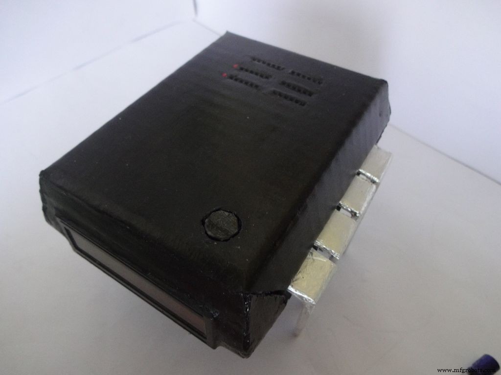

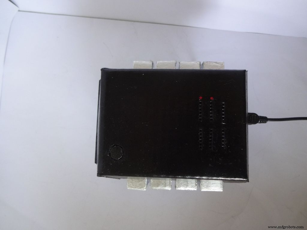
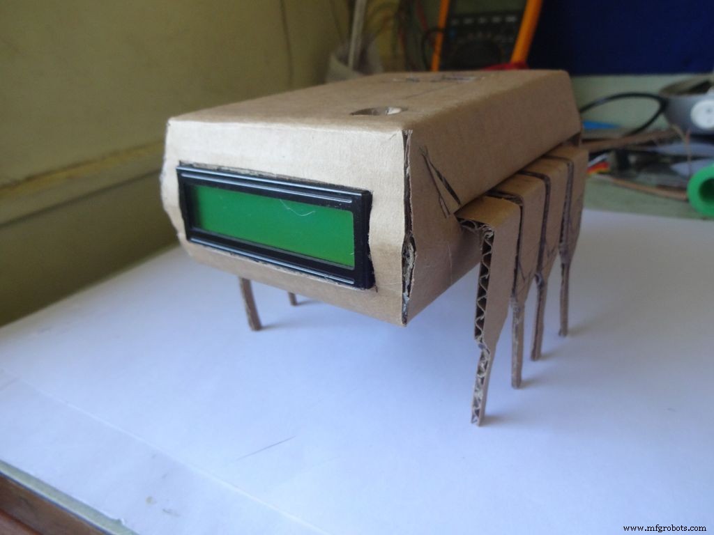
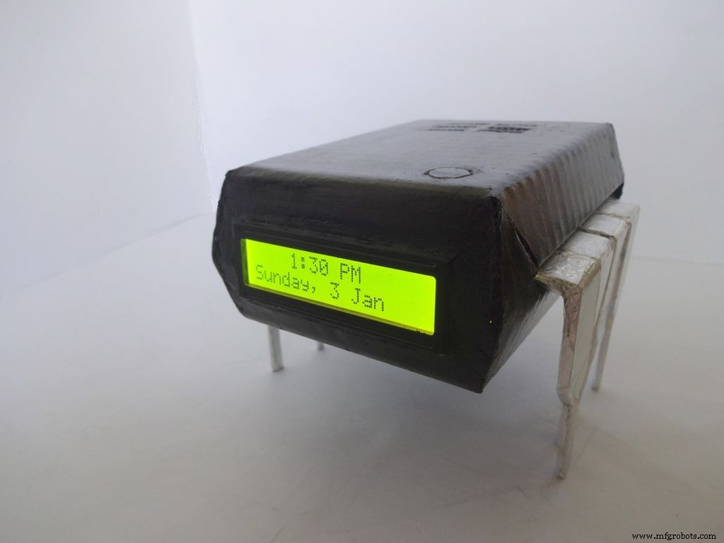
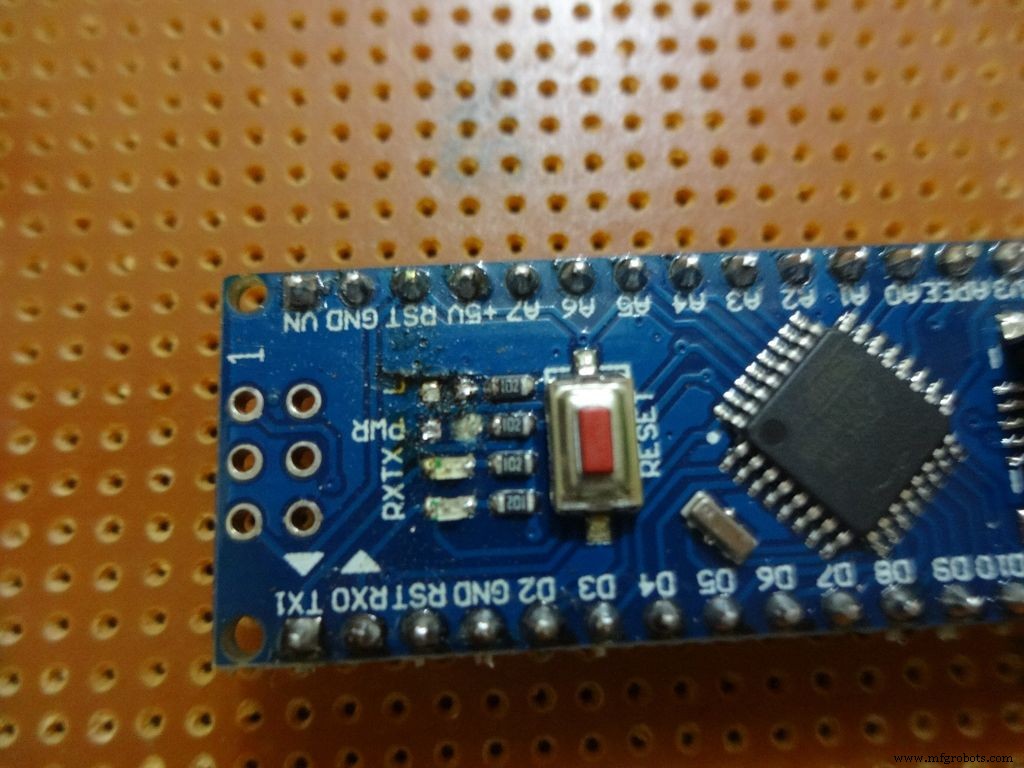
Le Companion IC est une horloge + un ohmmètre + un mesureur de capacité + un testeur de diode très cool ! Allumez-le en appuyant sur la broche 1 du circuit intégré ! Conservez-le sur votre établi pour un test rapide des composants et le temps de vérification. Peut fonctionner sur piles ou avec USB si vous avez une alimentation près de votre établi.
J'ai toujours voulu publier un projet mais je n'ai jamais rien trouvé d'unique à faire jusqu'à maintenant ! L'idée m'est venue lorsque j'ai voulu tester des condensateurs pour voir s'ils étaient défectueux ou non. Je n'avais qu'un multimètre disponible et il n'avait pas de fonction de mesure de capacité. Après avoir cherché à ce sujet, j'ai appris que l'Arduino pouvait le faire. J'ai décidé d'en faire un, mais voir les broches inutilisées sur l'Arduino n'était pas très satisfaisant, j'ai donc décidé d'ajouter un ohmmètre à gamme automatique, un testeur rapide LED/diode et une horloge RTC également ! Je voulais également qu'il mesure directement les valeurs en branchant le composant et n'utilise aucune sonde. La conception devait être unique, donc après quelques réflexions, la conception du circuit intégré a été réalisée !
Modifier (01/07/2016) :Un test de continuité facultatif a été ajouté, veuillez consulter la section commentaires.
Cet article explique en détail comment j'ai fait cela et comment vous aussi pouvez le faire vous-même. Il est adapté aux débutants et n'importe qui avec 2-3 semaines d'expérience Arduino/Electronics peut le construire !
La conception est modifiable et vous pouvez supprimer/ajouter de nouvelles fonctionnalités selon vos besoins. J'ai fait le boîtier avec du carton mais si vous avez les compétences, vous pouvez le faire avec du bois ou l'imprimer en 3D.
J'ai essayé de prendre et de joindre des photos à chaque étape que j'ai faite (beaucoup à chaque étape !). La plupart d'entre elles ont été prises plusieurs fois jusqu'à ce que j'obtienne le meilleur angle/lumière, mais certaines d'entre elles sont encore un peu floues car il est parfois difficile de tout tenir à deux mains.
J'ai cassé tout le code et le câblage en morceaux et en étapes, exactement comme je l'ai fait. Le code inclus est fortement commenté et correctement indenté. Alors que nous avançons. nous combinerons tout le code et le câblage étape par étape pour créer le circuit intégré final. Cela devrait aider tout le monde à le comprendre clairement. Si ce n'est pas le cas, faites-le moi savoir dans les commentaires.
Même si vous décidez de ne pas en faire un, essayez-le sur une planche à pain ou au moins lisez-le une fois car il doit y avoir une méthode ou une astuce ou quelque chose que vous pouvez apprendre ici et qui vous sera utile un jour (Sérieusement, vous ne savez jamais quand ça clique !)
Étape 1 :Outils et composants nécessaires
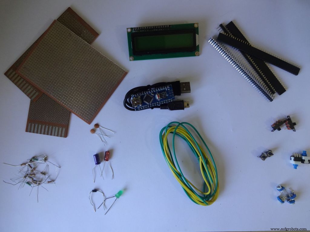

Liste des composants et matériaux utilisés (liens de magasin juste pour référence) :
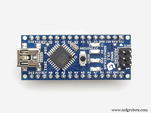
- 1x Arduino Nano V3, J'ai utilisé un clone avec CH340G -- ebay
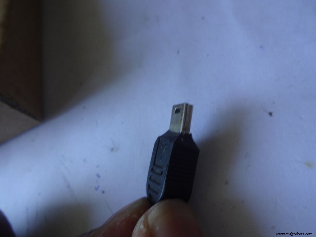
- Câble mini USB pour Arduino Nano -- Mini pas Micro !
- Carton -- J'ai utilisé une boîte d'emballage d'une épaisseur d'environ 2 mm. Demandez à votre voisin, à vos amis, allez fouiller si vous n'en trouvez pas.
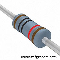
- 4x résistance 10k ohms -- facilement disponible
- 2x résistance 220 ohms -- facilement disponible
- 1x (1k, 4,7k, 47k, 100k) résistances ohms -- facilement disponible
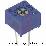
- 1x petit potentiomètre 10k ohms, pour le contrôle du contraste de l'écran LCD... n'importe quel écran de petite taille fonctionnera .-- ebay
- 2x Micro bouton poussoir, pour les boutons de réinitialisation et de changement de mode, ceux que vous utilisez couramment sur une maquette.
- 3 petits interrupteurs à glissière , pour activer le rétroéclairage, broches 0 et 1, ces broches doivent être désactivées lors de l'utilisation de la série -- ebay
- 1x Maintien/Bascule/Interrupteur poussoir à verrouillage, pour l'interrupteur d'alimentation -- ebay
- Certains condensateurs, diodes, leds juste pour tester, vous les utiliserez un jour de toute façon.
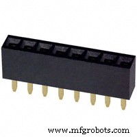
- 4x Bande à broches femelle -- ebay (40 broches par bande)
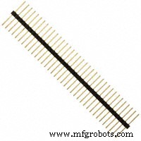
- 2x Bande à broches mâle -- ebay (40 broches par bande)
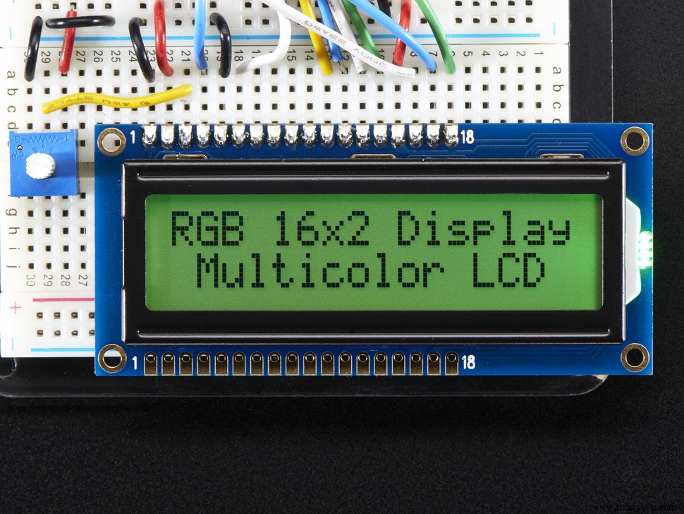
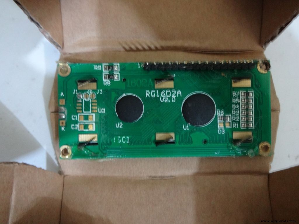
- 1x LCD 16x2 caractères -- ebay
- 1x module RTC DS3231 ou DS1307 (RTC signifie Real Time Clock) -- N'achetez pas de produits bon marché sur ebay. Ceux-ci utilisent de fausses puces et sont inexacts. Achetez ceci, ceci ou cela. N'importe lequel d'entre eux fonctionnera.
- 4x piles AA (ou AAA. Utiliser AAA sera beaucoup plus facile mais la capacité de la batterie est moindre)
- 1x 4 porte-piles AA (ou AAA) , variante plate -- ebay
- Fil monobrin , ceux utilisés pour les planches à pain, calibre 22
- Câble ruban (ou des fils à paires torsadées minces peuvent être utilisés) -- ebay
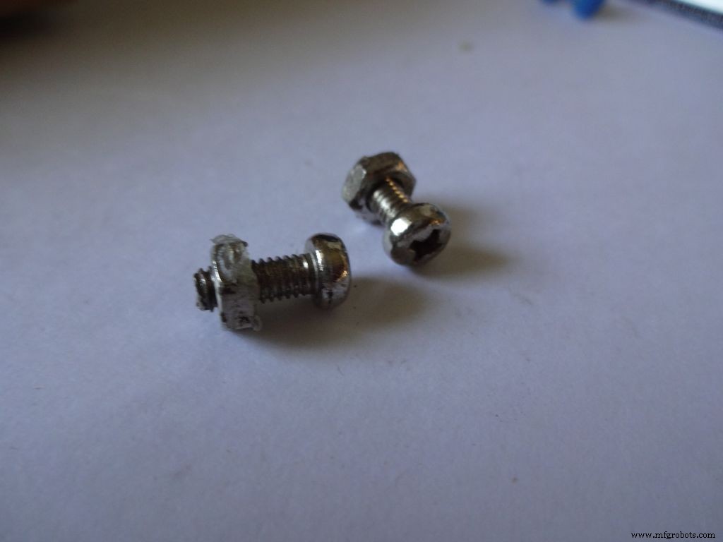
- 2x Petit écrou et boulon -- J'ai utilisé ceux de mon ancien ensemble Meccano (les boulons mesurent 1,3 cm de long)
- Peinture acrylique noire et pinceaux
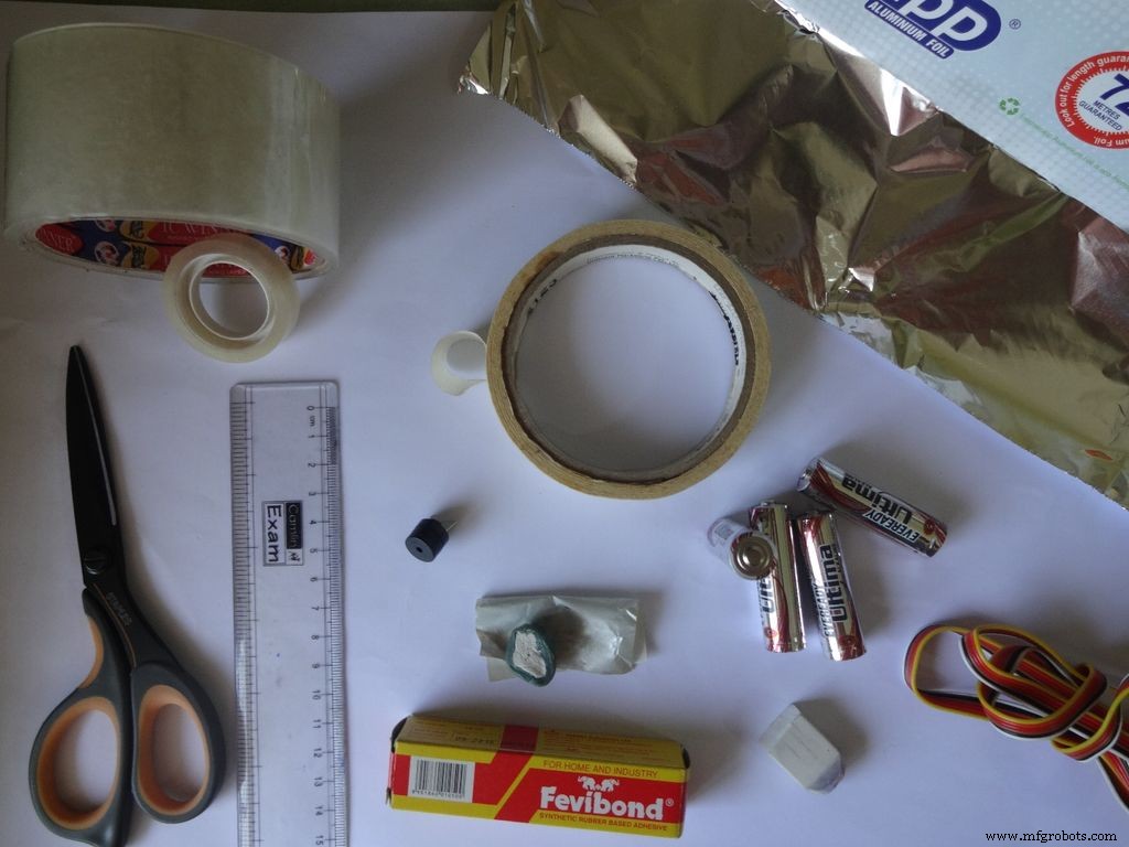
Outils nécessaires :
- Fer à souder
- Soudure
- Mèche/tresse à dessouder (pour quand vous le gâchez !)
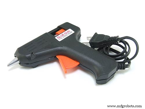
- Pistolet à colle
- Ruban de masquage
- Ruban pour violoncelle, transparent
- Dénudeur de fils, pince
- Coupe-boîte pointu
- Paire de ciseaux pointus
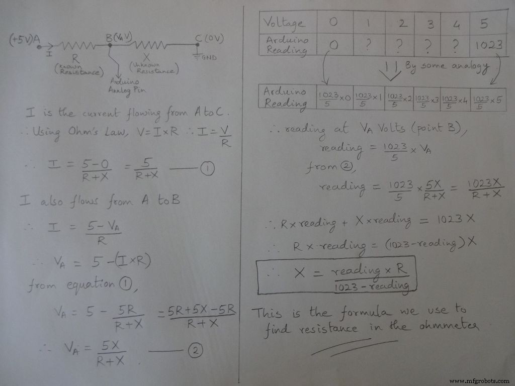
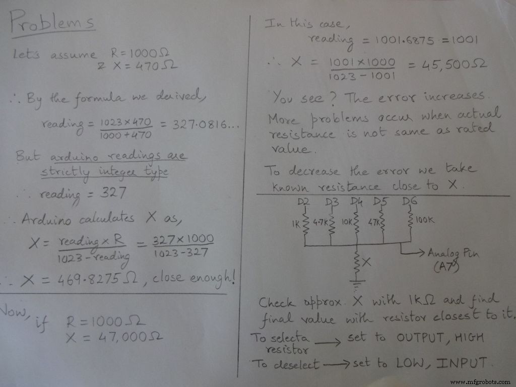
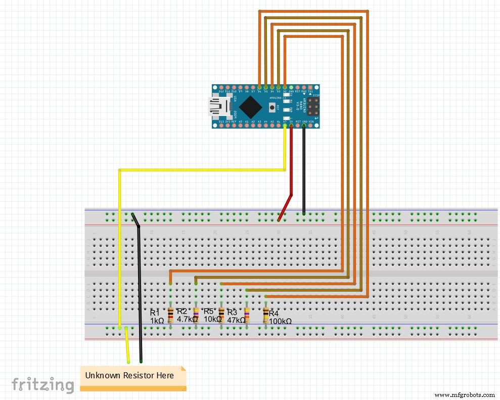
Étape 2 :Ohmmètre - Concept
L'idée de base de la mesure de la résistance vient du diviseur de tension.
Les valeurs de résistance sont modifiables, modifiez les valeurs de r1, r2, etc. Définissez également les plages (pour la plage automatique) en conséquence. Voir le code ci-dessous, téléchargez-le à partir des fichiers aux extrémités et testez l'ohmmètre sur une planche à pain
Si vous configurez Nano pour la première fois, le pilote CH340G pour celui-ci peut être téléchargé ici, fonctionne avec Windows 7, 8, 8.1 et 10. Les utilisateurs Mac vérifient ici.
Sélectionnez "Arduino Nano" dans le menu des cartes et le bon port COM. Téléchargez !
Code
//Broche analogique utilisée pour trouver la résistanceint Apin=7;//valeurs de r1 à r5float r1=1000;float r2=4700;float r3=10000;float r4=47000;float r5=10000;/ /pins de r1 à r5int r1_pin=2;int r2_pin=3;int r3_pin=4;int r4_pin=5;int r5_pin=6;float reading=0; // lire à partir de la broche analogique et stocker herefloat R=0; //calculer inconnu et stocker hereString finalR; //valeur finale à afficher avec unitsint caseno; //pour le débogage, stocke le numéro de cas // nous divisons toute la plage en cas et attribuons à chacun un numéro, au total 5 cas // cas1 :moins de 2850 // cas2 :2850 à 7350 // cas3 :7350 à 28500 // case4 :28500 à 73500 // case5 :plus de 73500#include // nécessaire pour convertir float en string, a la fonction String(float,n). Expliqué ci-dessous.void setup() { Serial.begin (9600);}void loop() { //nous trouvons d'abord une résistance inconnue en utilisant une résistance de 1kOhm //Par conséquent, désactivez R2, R3, R4 et R5 digitalWrite(r2_pin, LOW); //tournez chaque broche sur LOW avant de la définir comme INPUT pinMode(r2_pin, INPUT); // en le tournant INPUT lorsque sa valeur HIGH active la résistance de rappel interne digitalWrite(r3_pin, LOW); pinMode(r3_pin, INPUT); digitalWrite(r4_pin, LOW); pinMode(r4_pin, INPUT); digitalWrite(r5_pin, LOW); pinMode(r5_pin, INPUT); pinMode(r1_pin, SORTIE); digitalWrite(r1_pin, HAUT); //lire et calculer la résistance lecture=analogRead(Apin); R=(lecture*r1)/(lecture 1023); // si valeur <2850, finalR =valeur(en utilisant 1kOhm) if(R<2850){ caseno=1; if(R<1000){ //si la valeur est inférieure à 1000, utilisez "Ohm" et non "kOhm" finalR =String(R,2) + "Ohm" ; //Chaîne(float,n) Conversion de flottant en chaîne avec n chiffres après la virgule // attache "Ohm" après la valeur à la chaîne, '+' joint deux chaînes ici } else{ //utilise "kOhm R=R/1000; finalR =String(R,2) + "kOhm"; } } //si valeur entre 2850 et 7350 , utiliser la valeur obtenue par 4.7kOhm else if(R>=2850 &&R<7350){ caseno=2; digitalWrite(r1_pin , LOW); //Activer uniquement pinMode 4,7kOhm (r1_pin, INPUT); digitalWrite(r3_pin, LOW); pinMode(r3_pin, INPUT); digitalWrite(r4_pin, LOW); pinMode(r4_pin, INPUT); digitalWrite(r5_pin, LOW); ); pinMode(r5_pin, INPUT); pinMode(r2_pin, OUTPUT); digitalWrite(r2_pin, HIGH); lecture=analogRead(Apin); R=(reading*r2)/(1023-reading)/1000; finalR =String( R,2) + "kOhm"; } //si valeur entre 7350 et 28500, utiliser la valeur obtenue par 10kOhm else if(R>=7350 &&R<28500){ caseno=3; digitalWrite(r1_pin, LOW); pinMode( r1_pin, INPUT ; digitalWrite(r2_pin, LOW); pinMode(r2_pin, INPUT); digitalWrite(r4_pin, LOW); pinMode(r4_pin, INPUT); digitalWrite(r5_pin, LOW); pinMode(r5_pin, INPUT); pinM ode(r3_pin, SORTIE); digitalWrite(r3_pin, HAUT); lecture =lecture analogique (Apin); R=(lecture*r3)/(1023-lecture)/1000 ; finalR=Chaîne(R,2) + "kOhm" ; } //si valeur entre 28500 et 73500, utiliser la valeur obtenue par 47kOhm else if(R>=28500 &&R<73500){ caseno=4; digitalWrite(r1_pin, LOW); pinMode(r1_pin, INPUT); digitalWrite(r2_pin, LOW); pinMode(r2_pin, INPUT); digitalWrite(r3_pin, LOW); pinMode(r3_pin, INPUT); digitalWrite(r5_pin, LOW); pinMode(r5_pin, INPUT); pinMode(r4_pin, SORTIE); digitalWrite(r4_pin, HAUT); lecture =lecture analogique (Apin); R=(lecture*r4)/(1023-lecture)/1000 ; finalR =Chaîne(R,2) + "kOhm" ; } //si valeur supérieure à 73500, utiliser la valeur obtenue par 100kOhm else if(R>=73500){ caseno=5; digitalWrite(r1_pin, LOW); pinMode(r1_pin, INPUT); digitalWrite(r2_pin, LOW); pinMode(r2_pin, INPUT); digitalWrite(r3_pin, LOW); pinMode(r3_pin, INPUT); digitalWrite(r4_pin, LOW); pinMode(r4_pin, INPUT); pinMode(r5_pin, SORTIE); digitalWrite(r5_pin, HAUT); lecture =lecture analogique (Apin); R=(lecture*r5)/(1023-lecture)/1000 ; finalR =Chaîne(R,2) + "kOhm"; } Serial.println(finalR); //impression de la chaîne finale avec les unités Serial.println(" "); retard(1000);}
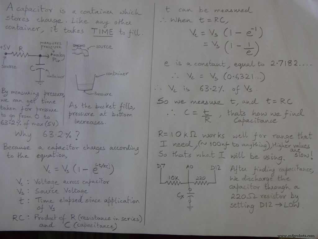
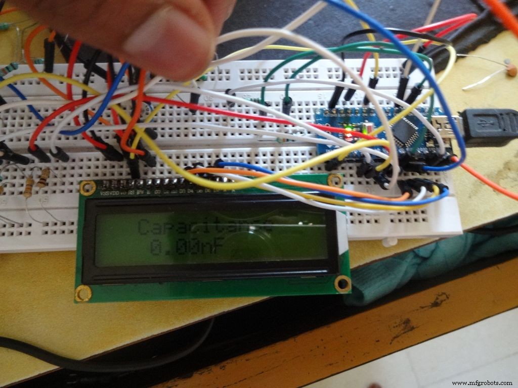
Étape 3 : Capacimètre - Concept

Code
/* RCTiming_capacitance_meter * concept de code tiré de Paul Badger 2008 * * La tension du condensateur à une constante de temps est définie comme 63,2 % de la tension de charge. * c'est-à-dire qu'un condensateur est rempli à 63,2 % de sa capacité totale en 1 constante de temps */ int analogPin=0; // broche analogique pour mesurer la tension du condensateur int chargePin=7; // broche pour charger le condensateur - connecté à une extrémité de la résistance de charge int déchargePin=12; // broche pour décharger le condensateur, même utilisé pour le test de diode (chechPin1) float resistanceValue=10000.0; // Nous utilisons une résistance de 10kOhm non signée long startTime; Temps écoulé long non signé ; flotteur microFarads; // variable à virgule flottante pour préserver la précision, faire les calculs float nanoFarads;void setup(){ pinMode(chargePin, OUTPUT); // définit chargePin pour produire digitalWrite(chargePin, LOW); Serial.begin(9600); // initialise la transmission série pour le débogage}boucle vide(){ digitalWrite(chargePin, HIGH); // définit chargePin HIGH et le chargement du condensateur startTime =millis(); while(analogRead(analogPin) <648){ // 647 est 63,2% de 1023, ce qui correspond à la tension à pleine échelle } elapsedTime=millis() - startTime; // convertir les millisecondes en secondes ( 10^-3 ) et les Farads en microFarads ( 10^6 ), net 10^3 (1000) microFarads =((float)elapsedTime / resistorValue) * 1000; // (float) convertit le temps écoulé "unsigned long" en float Serial.print(elapsedTime); // affiche la valeur sur le port série Serial.print(" mS "); // imprime les unités if (microFarads> 1){ Serial.print((long)microFarads); // affiche la valeur sur le port série Serial.println(" microFarads"); // imprime les unités } else { // si la valeur est inférieure à un microFarad, convertit en nanoFarads (10^-9 Farad). nanoFarads =microFarads * 1000,0 ; // multiplier par 1000 pour convertir en nanoFarads (10^-9 Farads) Serial.print((long)nanoFarads); // affiche la valeur sur le port série Serial.println(" nanoFarads"); // imprime les unités } /* décharge le condensateur */ digitalWrite(chargePin, LOW); // définir la broche de charge sur LOW pinMode (dischargePin, OUTPUT); // définit la broche de décharge pour produire digitalWrite(dischargePin, LOW); // mettre la broche de décharge LOW while(analogRead(analogPin)> 0){ // attendre que le condensateur soit complètement déchargé } pinMode(dischargePin, INPUT); // remettre la broche de décharge à l'entrée}
Étape 4 :Test de diode
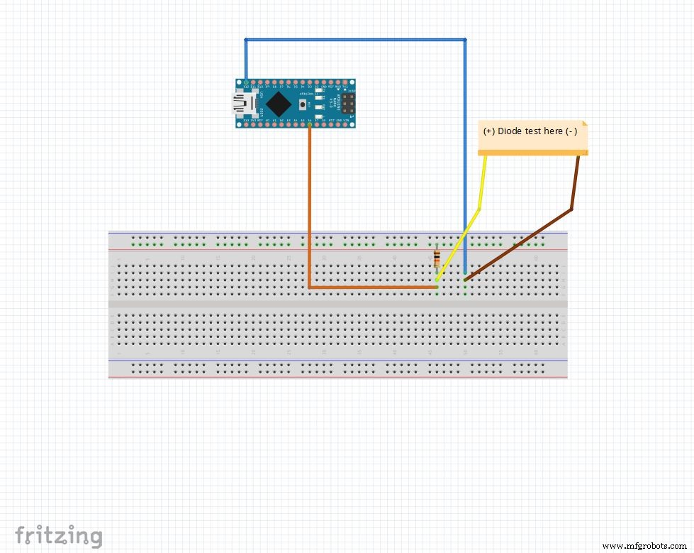
La broche analogique est tirée jusqu'à 5V avec la résistance de 10k Ohm. Donc la broche analogique lit 1023 quand rien n'est connecté. D12 est défini sur SORTIE , FAIBLE .
Lorsqu'une diode est polarisée en direct entre la broche analogique (5V ) et D12 (GND ), broche analogique lit 100-400 .
Lorsqu'il est polarisé en inverse, pratiquement un très petit courant circule et broche analogique lit 900-1023 .
De cette façon, nous pouvons simplement trouver les côtés p et n de n'importe quelle diode. Cela peut être utilisé pour vérifier rapidement les LED et les diodes.
Code
String state ="null";int checkPin1 =12;int checkPin2 =6;void setup() { Serial.begin(9600);}void loop() {pinMode(checkPin1, OUTPUT); digitalWrite(checkPin1, LOW); // la broche 11 est réglée sur faible // la lecture analogique est normalement tirée par la résistance de 10 k, donc la lecture nulle est de 1023// En polarisation directe, la broche analogique est connectée à checkPin1, qui est FAIBLE. Donc, lire moins de 1023//Pratiquement, un petit courant circule également en polarisation inverse, nous prenons donc 700 pour différencier if(analogRead(checkPin2)<700){ state="forward"; } Serial.println(état); Serial.println(analogRead(checkPin2)); état ="null" ; retard(500);}
Étape 5 :L'horloge temps réel (RTC)
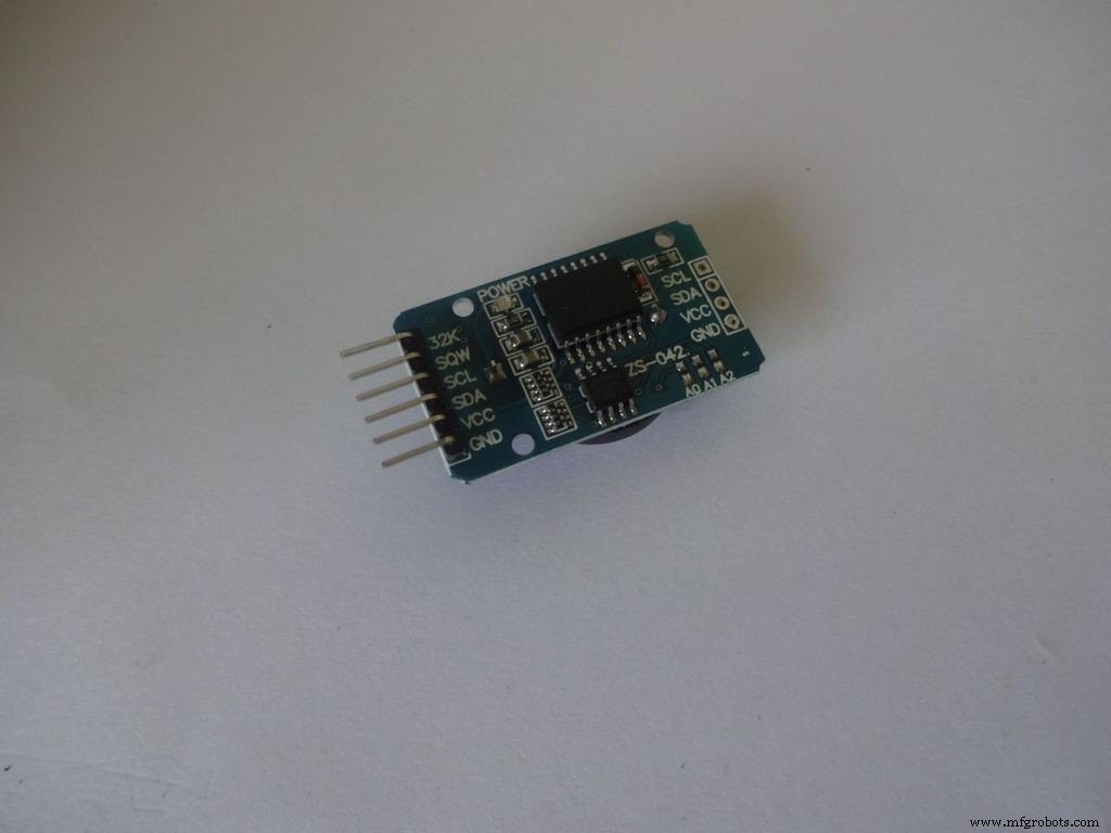
Le RTC conserve les informations sur les secondes, les minutes, les heures, le jour, la date, le mois et l'année. Il continue à compter même lorsque l'alimentation externe est coupée grâce à la petite pile bouton qu'il contient. La date de fin de mois est automatiquement ajustée pour les mois de moins de 31 jours, y compris les corrections pour les années bissextiles.
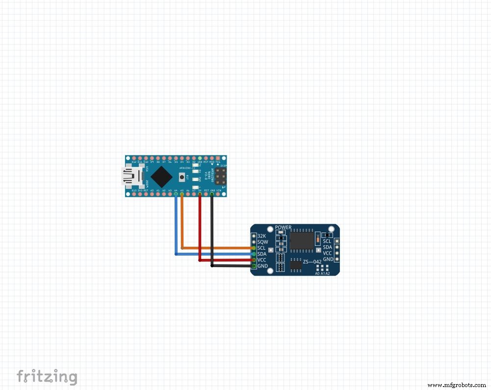
Quel que soit le module que vous avez, nous utiliserons 4 broches :Vcc , GND , SDA et SCL . Le SDA et SCL les broches sur l'arduino nano et uno sont A4 et A5 respectivement. Pour les autres arduinos, cherchez sur Google !
Nous utiliserons la bibliothèque "RTClib", qui rend le réglage et l'accès à l'heure super facile ! La bibliothèque peut être téléchargée ici (Cliquez sur "Télécharger ZIP", et extrayez le "RTClib-master" dans votre dossier Bibliothèques Arduino. En savoir plus sur l'installation des bibliothèques.)
Pour régler l'heure, téléchargez le "RTC_set_time.ino" joint à cette étape et décommentez les lignes,
rtc.adjust(DateTime(F(__DATE__), F(__TIME__)));
Si vous souhaitez utiliser l'heure définie sur votre ordinateur lors de la compilation. Ou
rtc.adjust(DateTime(2014, 1, 21, 3, 0, 0)); //année, mois, date, heure, minute, secondes
Pour définir une heure personnalisée.
Connectez-vous comme indiqué et téléchargez. Ouvrir Série moniteur à 9600 baud pour voir l'heure actuelle. Vérifiez à nouveau après quelques heures pour voir comment le RTC rattrape son retard.
Assurez-vous de recommander ces lignes et de les télécharger à nouveau après avoir réglé l'heure une fois. Sinon, vous continuerez à le réinitialiser à chaque réinitialisation d'Arduino !
Code
// Fonctions date et heure utilisant un DS1307 RTC connecté via I2C et Wire lib#include #include RTC_DS1307 rtc;//création de l'objet "rtc" de RTC_DS1307, objets sont utilisés pour accéder aux fonctions //plus sur les objets et les classes :https://www.youtube.com/watch?v=ABRP_5RYhqUchar daysOfTheWeek[7][12] ={"Sunday", "Monday", "Tuesday", " Mercredi", "Jeudi", "Vendredi", "Samedi"};configuration void () { Serial.begin(9600); rtc.begin(); // la ligne suivante définit le RTC sur la date et l'heure de compilation de ce croquis // rtc.adjust(DateTime(F(__DATE__), F(__TIME__))); // Cette ligne définit le RTC avec une date et une heure explicites, par exemple pour définir // le 21 janvier 2014 à 3 heures du matin, vous appelleriez :// rtc.adjust(DateTime(2014, 1, 21, 3, 0, 0) );}boucle vide () { DateTime now =rtc.now(); Serial.print(now.year()); Serial.print('/'); Serial.print(maintenant.mois()); Serial.print('/'); Serial.print(now.day()); Serial.print(" ("); Serial.print(daysOfTheWeek[now.dayOfTheWeek()]); Serial.print(") "); Serial.print(now.hour()); Serial.print(':'); Serial.print(now.minute()); Serial.print(':'); Serial.print(now.second()); Serial.println(); Serial.println(); retard(1000);}
Étape 6 :Configuration finale
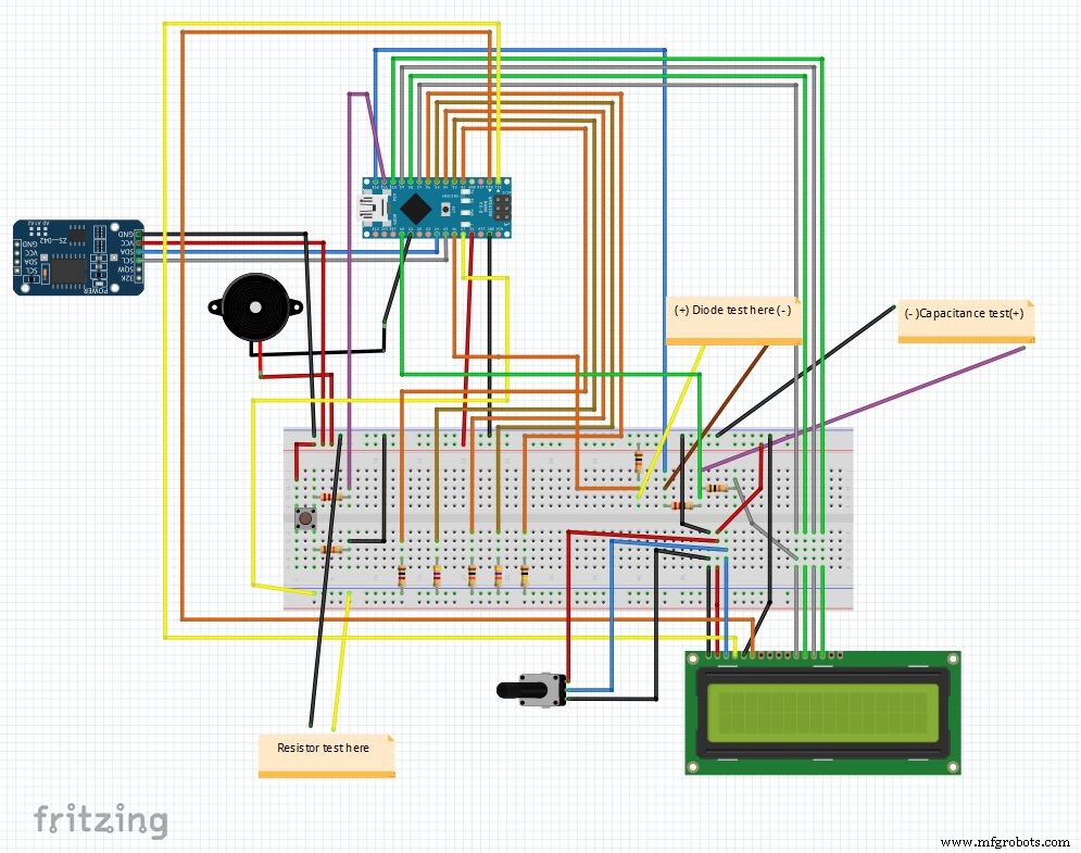
C'est donc le dernier circuit après avoir combiné tous les éléments. Le code principal et le fichier fritzing sont joints à la fin.
Téléchargez fritzing depuis fritzing.org si vous ne l'avez pas déjà fait.
Extrayez le fichier Main_code.rar et ouvrez Main_file_rtc.ino. J'ai inclus toutes les déclarations de variables dans un definations.h séparé fichier d'en-tête, il sera ajouté automatiquement lorsque vous ouvrez le code principal.
Les différentes parties sont transformées en fonctions : Clock() , findRésistance() , findCapcitance() et diodeTest() . Ceux-ci sont écrits dans des onglets séparés, ce qui facilite la lecture et les modifications sont faciles à mettre en œuvre. Le fichier principal vérifie simplement l'état du "bouton de mode" et appelle les fonctions appropriées.
D'autres détails sont correctement expliqués dans le code lui-même.
Après un test sur une maquette, nous sommes prêts à commencer à fabriquer l'IC !
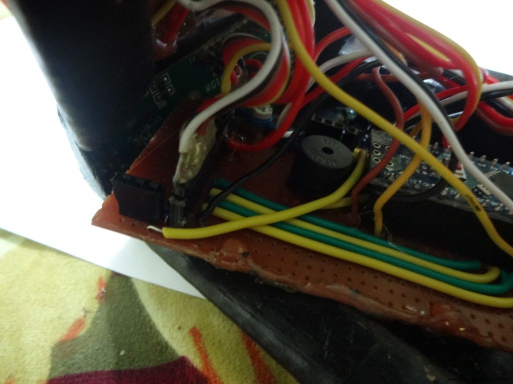
Remarque :Le buzzer, s'il n'est pas encore utilisé, peut être utilisé si nécessaire, par exemple, une fonction de continuité.
Étape 7 :Préparation des commutateurs
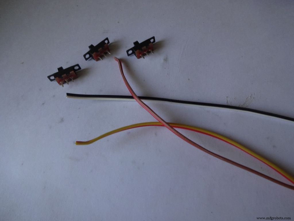
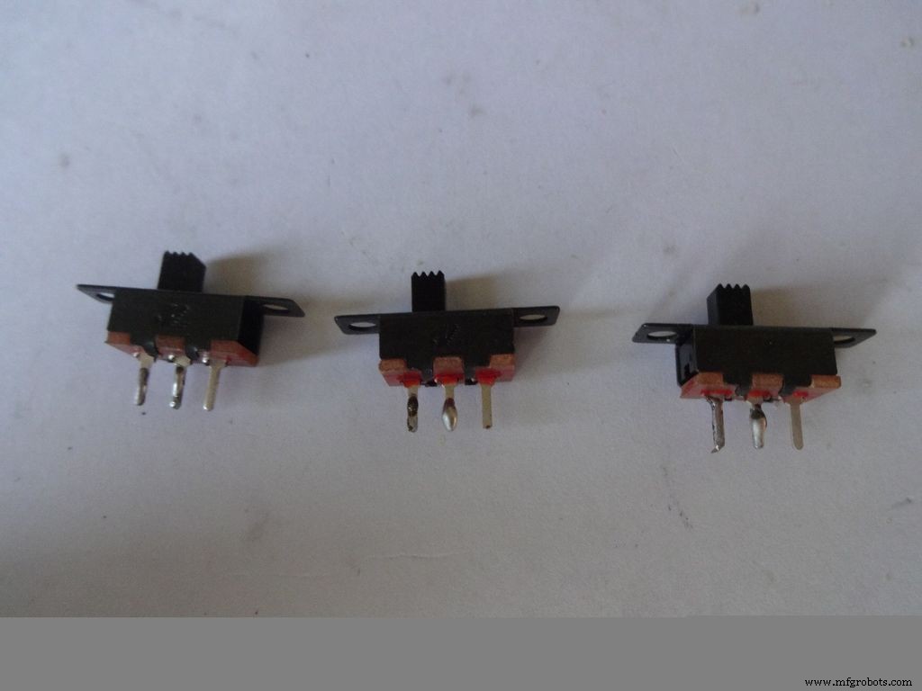


Prenez les 3 interrupteurs à glissière avec 3 paires de fils d'environ 10 cm de long. J'ai coupé le câble plat pour ça.
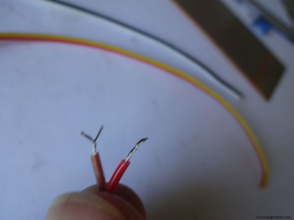
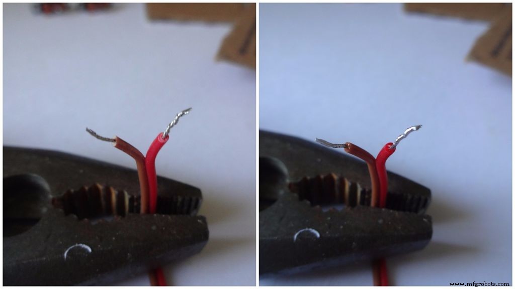
Dénudez une petite partie de l'isolant (pas plus de 5 mm) et torsadez les brins.
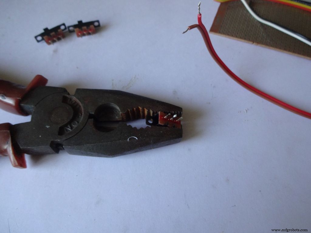
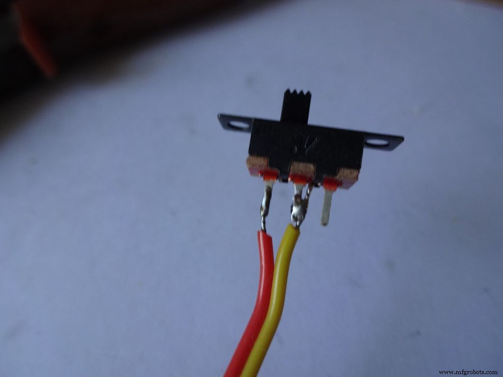
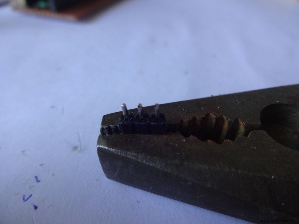
Appliquez de la soudure sur 2 broches adjacentes de chacun des commutateurs. Utilisez quelque chose pour le maintenir en place pendant que vous soudez, j'ai utilisé une pince lourde.
Si vous n'avez jamais soudé auparavant, c'est le bon moment pour commencer. Youtube a des tonnes de vidéos pour vous expliquer comment souder correctement. Les leçons de PACE sont très instructives, veuillez les regarder.
Ensuite, nous devons « étamer » les fils. Touchez la pointe du fer à souder sur le fil à étamer. Appliquez un tout petit peu de soudure entre la pointe et le fil, cela crée un pont qui conduit la chaleur de la pointe au fil. Ensuite, vous appliquez la soudure directement sur le fil, du côté opposé de la panne du fer à souder . Retirez la soudure. Retirez la pointe. Une vidéo à ce sujet.
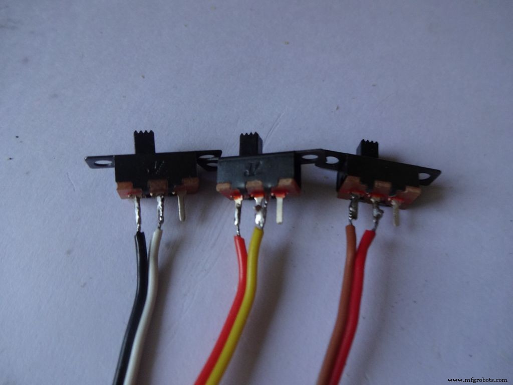
Après cela, maintenez l'interrupteur en place, amenez l'un des fils étamés à la broche et refusionnez la soudure en touchant le fer à souder. Faites de même avec le deuxième fil. Remarquez que j'ai mis les fils de couleur foncée d'un côté des interrupteurs.
Maintenant, répétez la procédure et attachez deux fils à un bouton-poussoir (ce sera le bouton de réinitialisation). Assurez-vous de ne pas mettre de fils aux extrémités normalement connectées du bouton.
Étape 8 :Faire le boîtier - Découper la mise en page
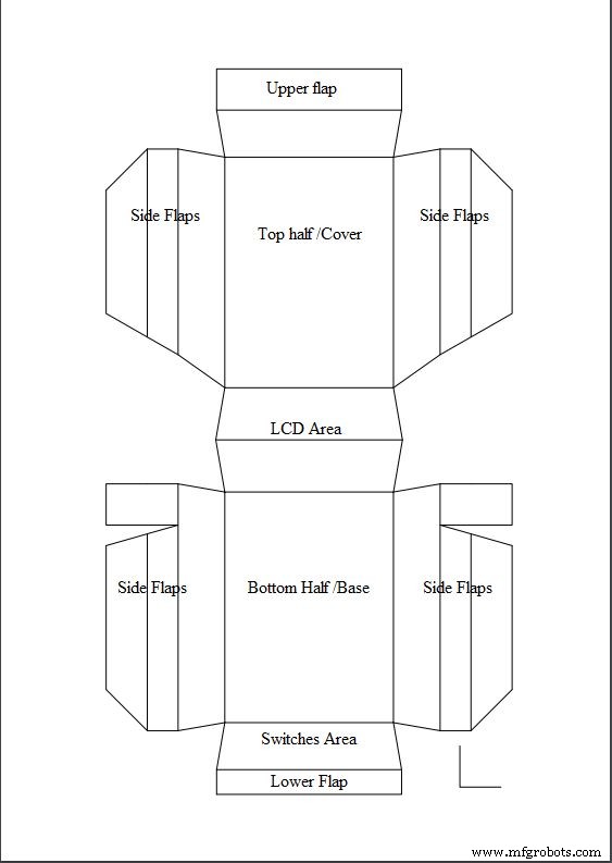
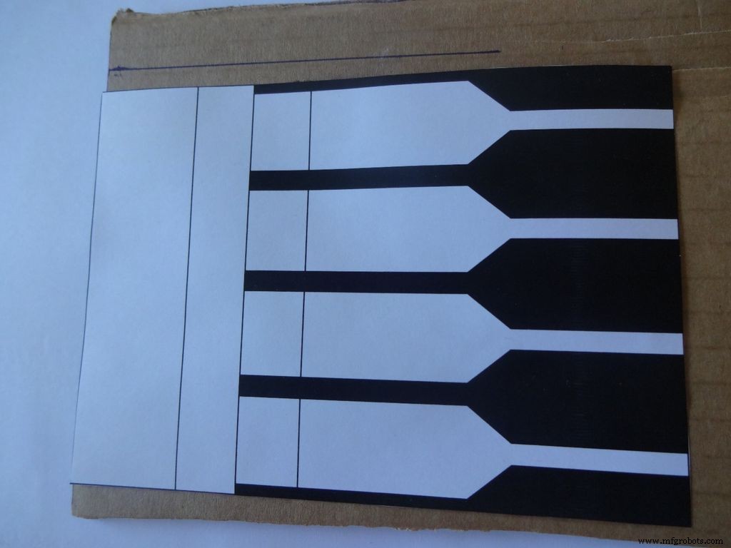
Téléchargez "Layout_Final_A3.pdf" ou ""Layout_Final_ANSI_B.pdf", en fonction du format de papier disponible dans votre région. joint à la fin.
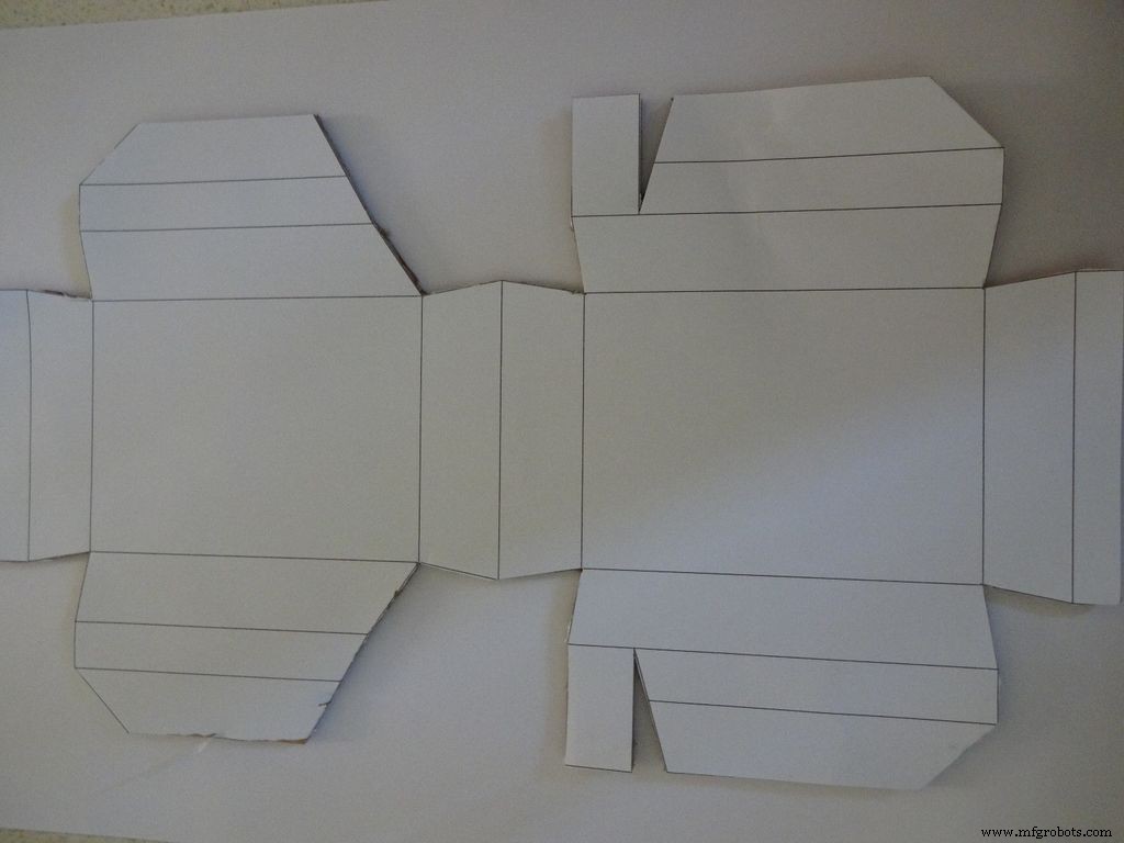
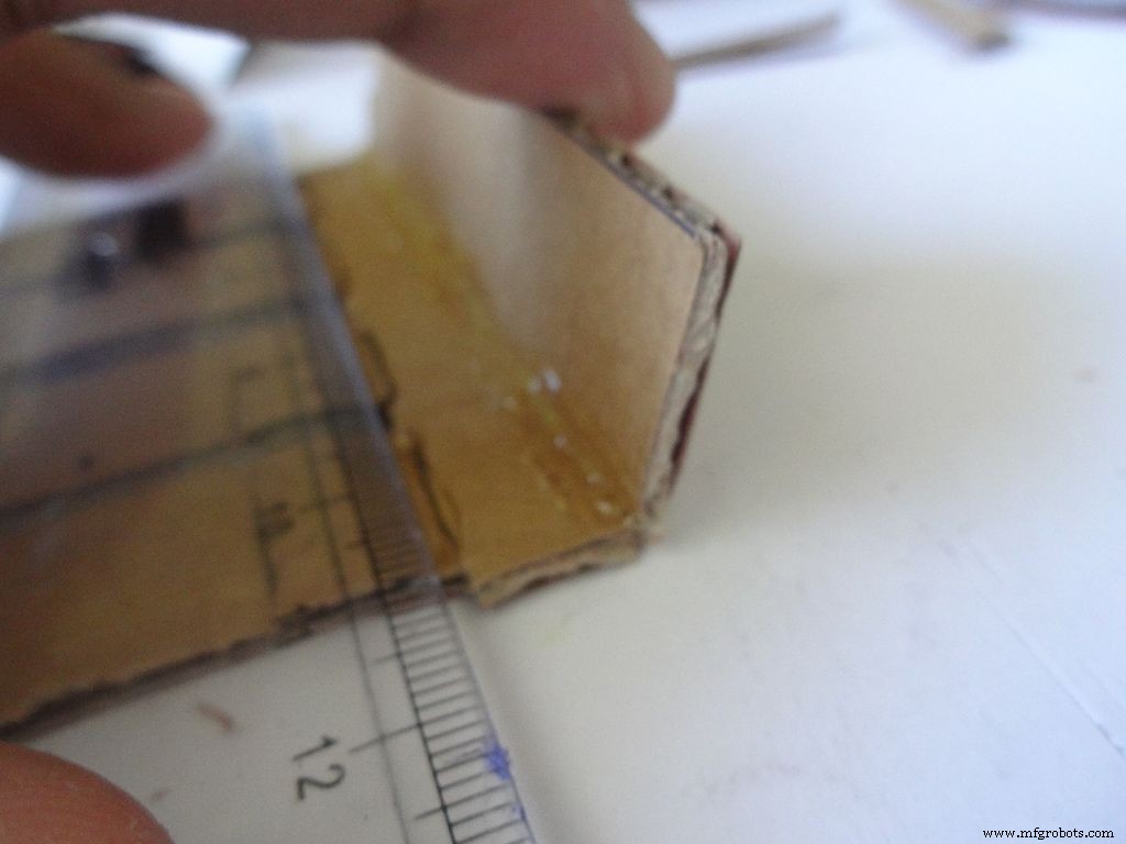
Imprimez-le sur un papier au format A3 (29,7 x 42,0 cm ou 11,69 x 16,53 pouces) ou sur l'alternative américaine ANSI B (11 x 17 pouces ou 279 × 432 mm). Assurez-vous que lors de l'impression, vous sélectionnez le format de papier et l'orientation appropriés et sélectionnez l'option « Taille réelle ». Confirmez que l'impression est précise en mesurant le petit angle droit dans le coin inférieur droit, il doit mesurer 2 cm x 2 cm.
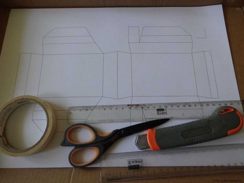
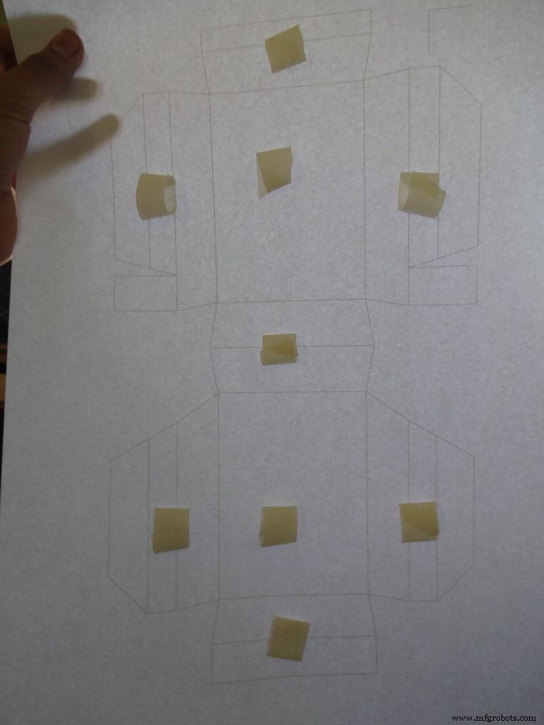
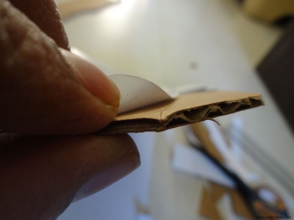
Coupez un morceau de carton à peu près plus que la mise en page. Déchirez un petit morceau de ruban adhésif, formez un rouleau « collant double face » et fixez-le aux endroits indiqués. Collez ensuite la feuille sur le carton.
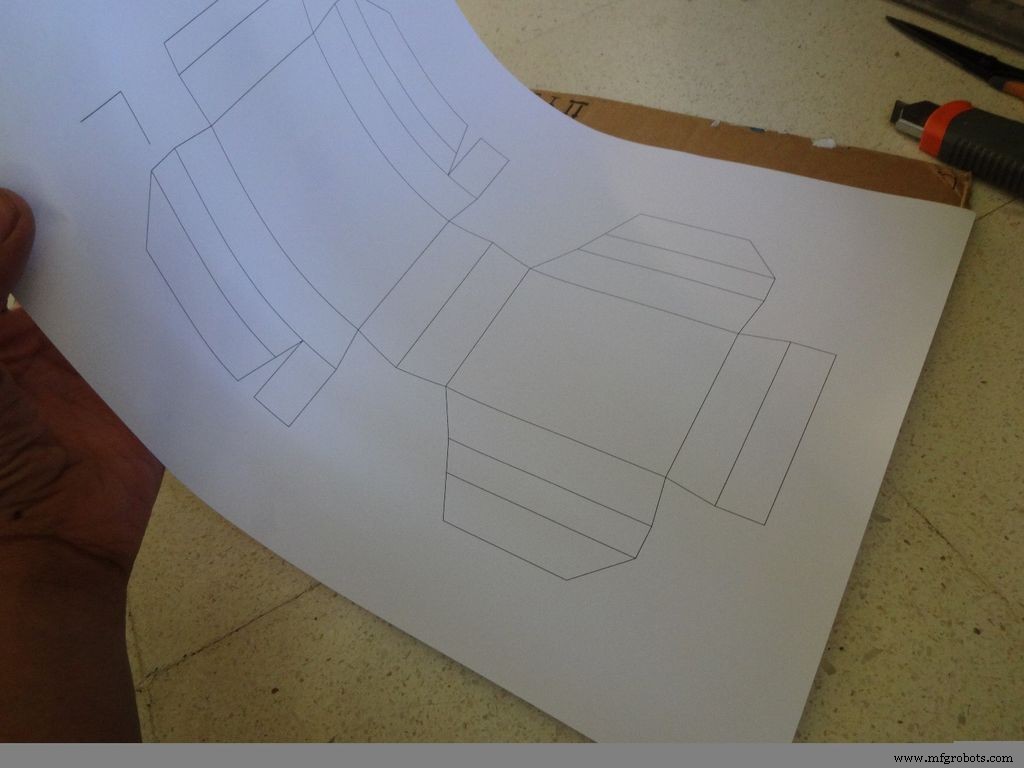
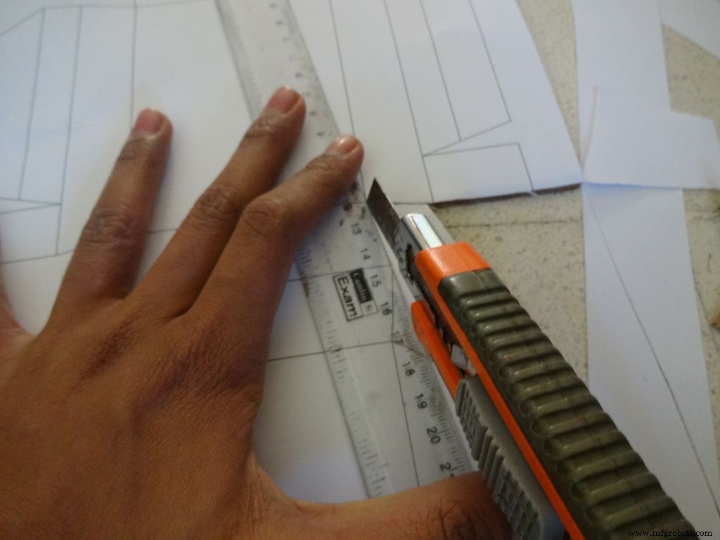
Utilisez des ciseaux pointus ou un cutter avec une règle pour couper la limite extérieure de la disposition du boîtier. J'ai trouvé les cutters bien meilleurs que les ciseaux. La plupart des couteaux auront des lames qui peuvent être cassées par étapes pour obtenir une pointe fraîche et tranchante, il est donc recommandé de le faire. Gardez un autre morceau de carton ou de bois sous la partie que vous coupez, cela aide à obtenir des coupes plus nettes.
De plus, ne pas garder la règle correctement sur la ligne pendant la coupe est une erreur courante. Ne le faites pas trop vite.
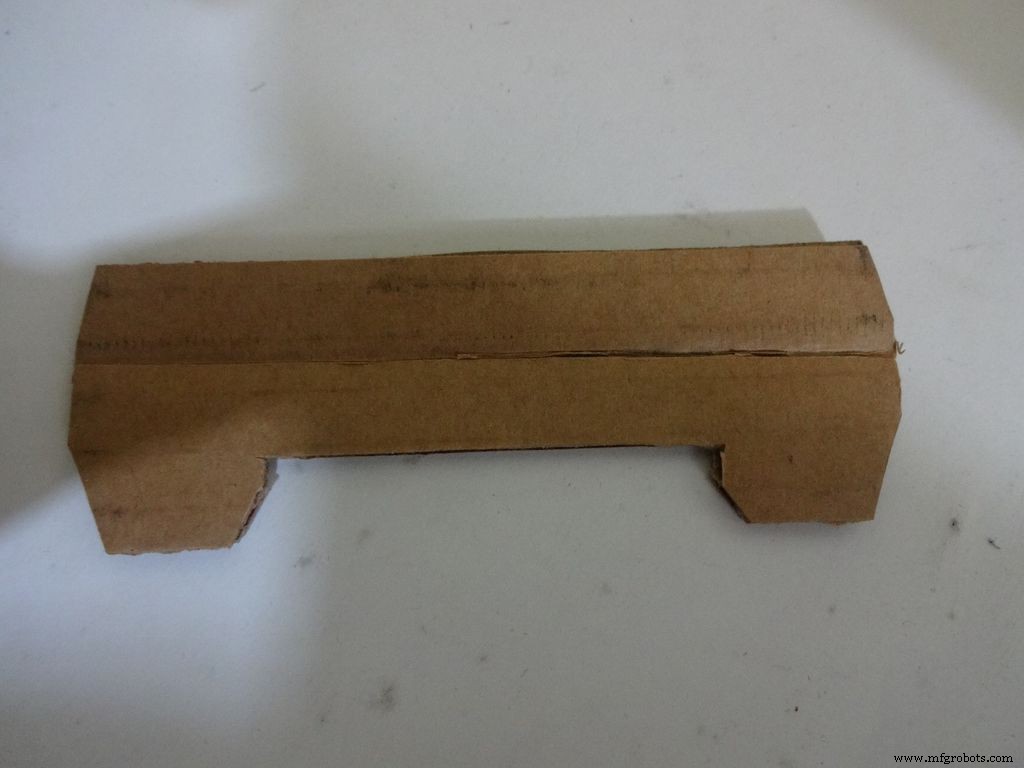
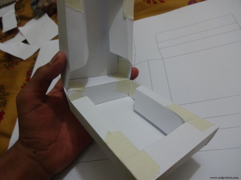
Étape 9 :Fabrication de l'étui - Pliage et pliage
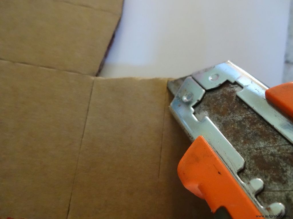
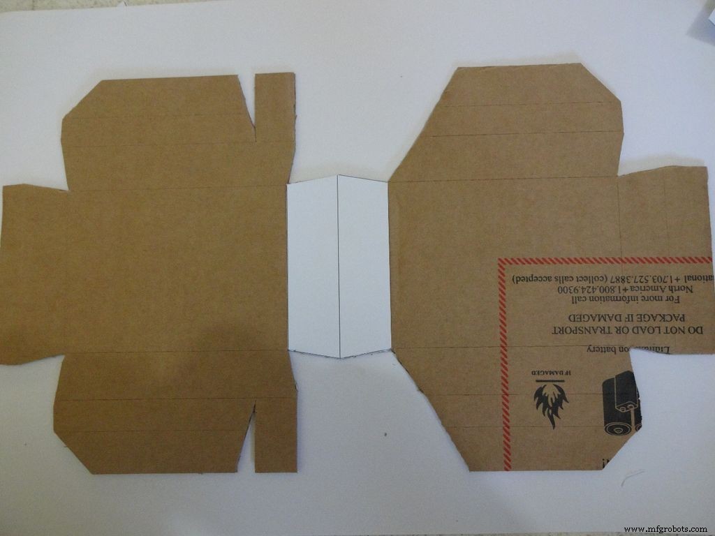
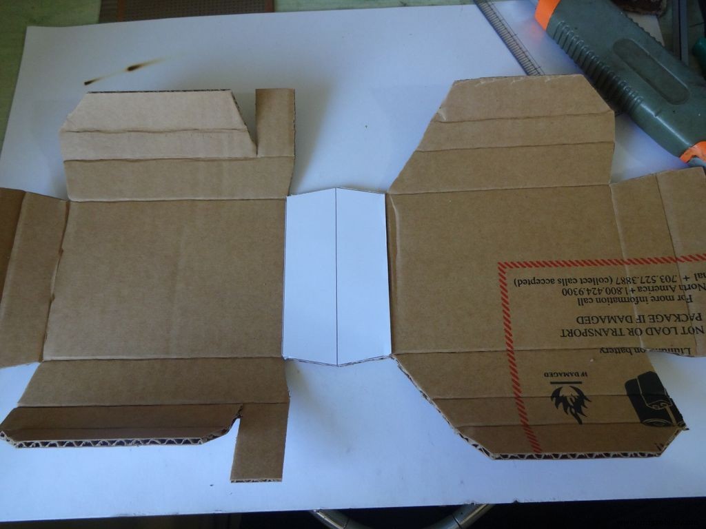


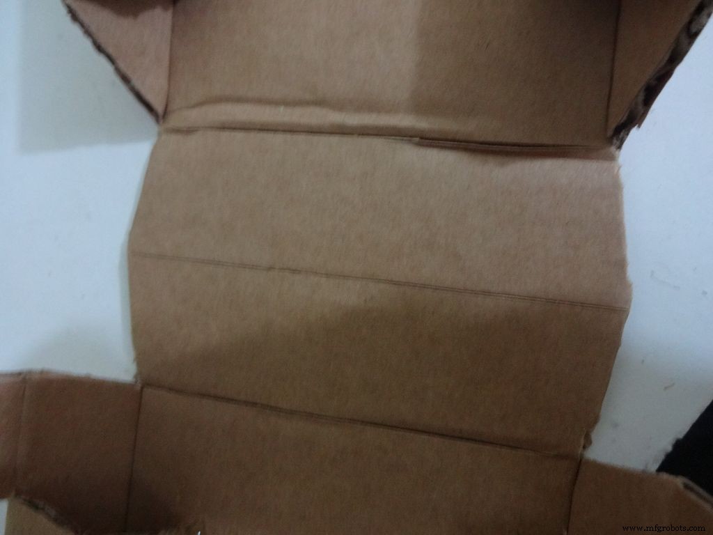
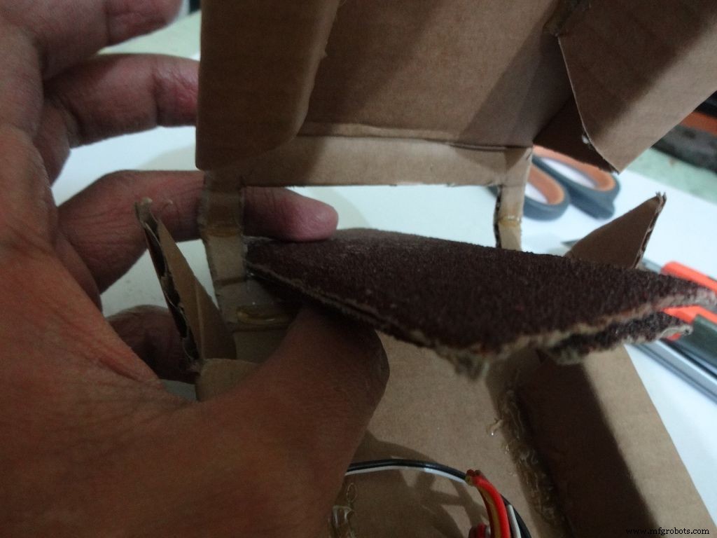
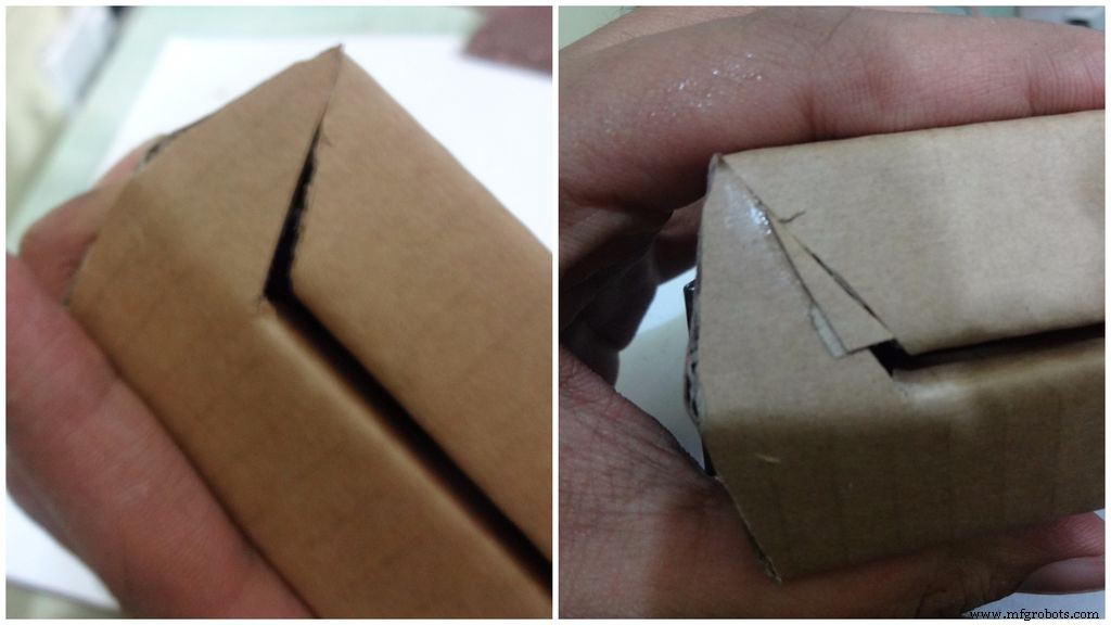
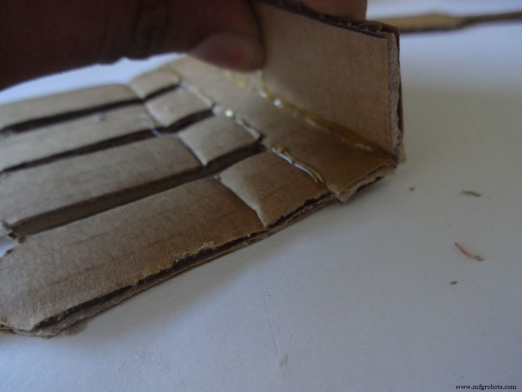
À l'aide du cutter avec l'échelle, faites soigneusement des plis le long de toutes les lignes de pliage, à l'exception de la ligne médiane dans la zone LCD. Pliez et pliez toutes les parties pliables et rectifiez les plis incomplets.
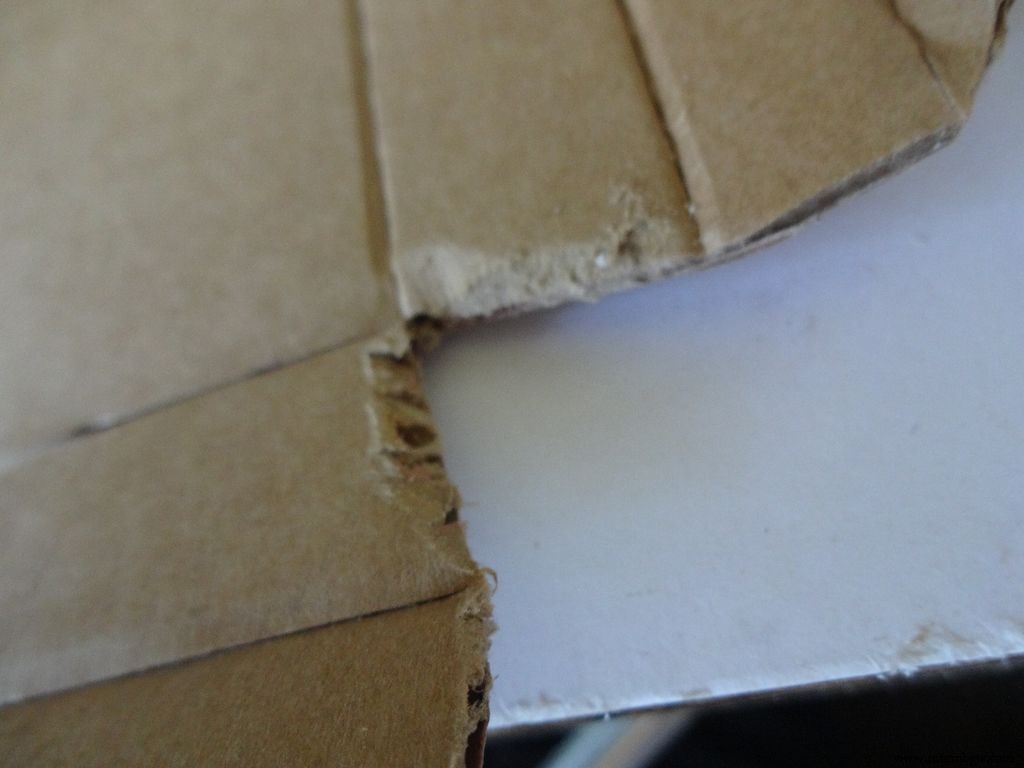
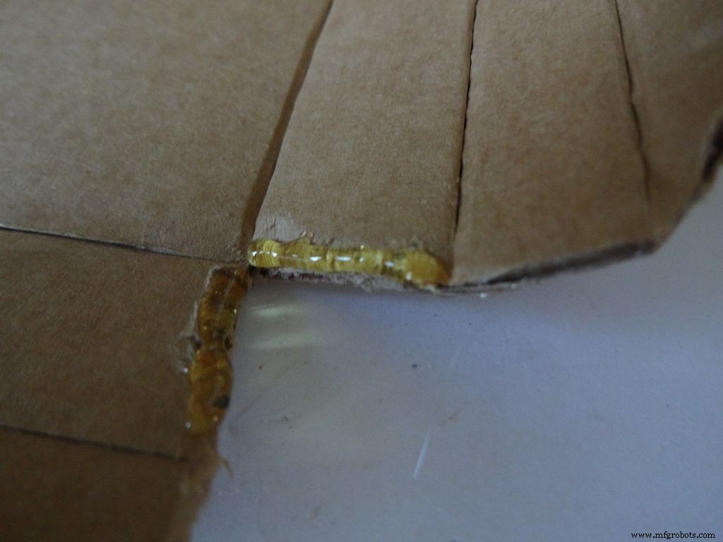
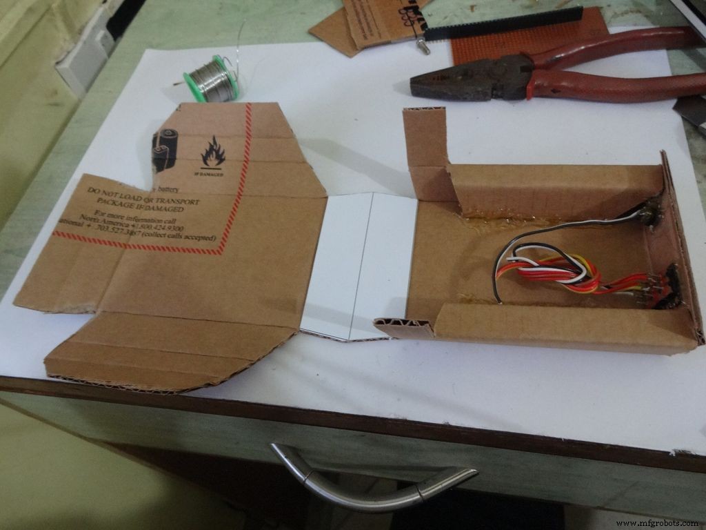
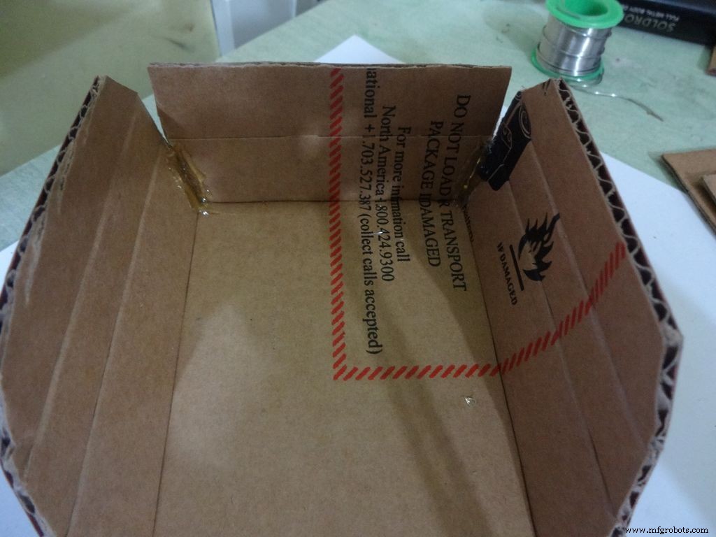
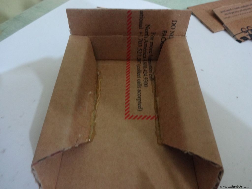
Pour la moitié inférieure ou la base :
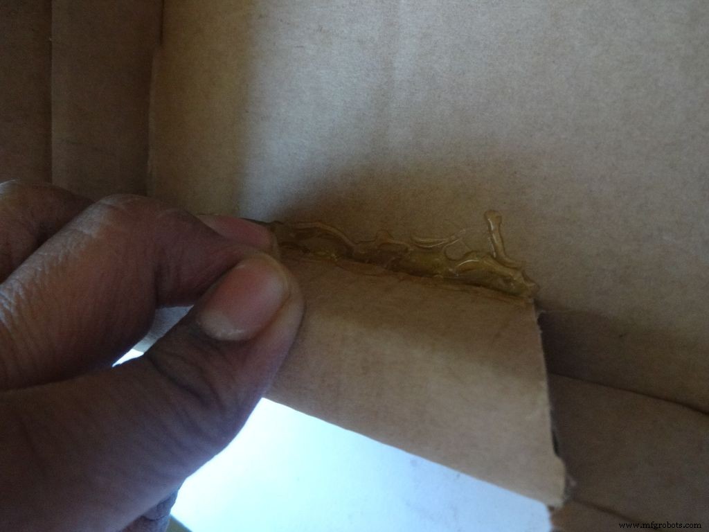
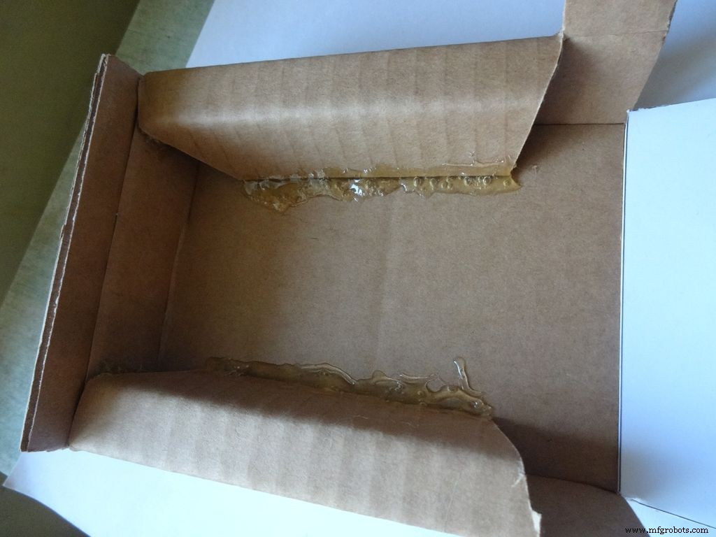
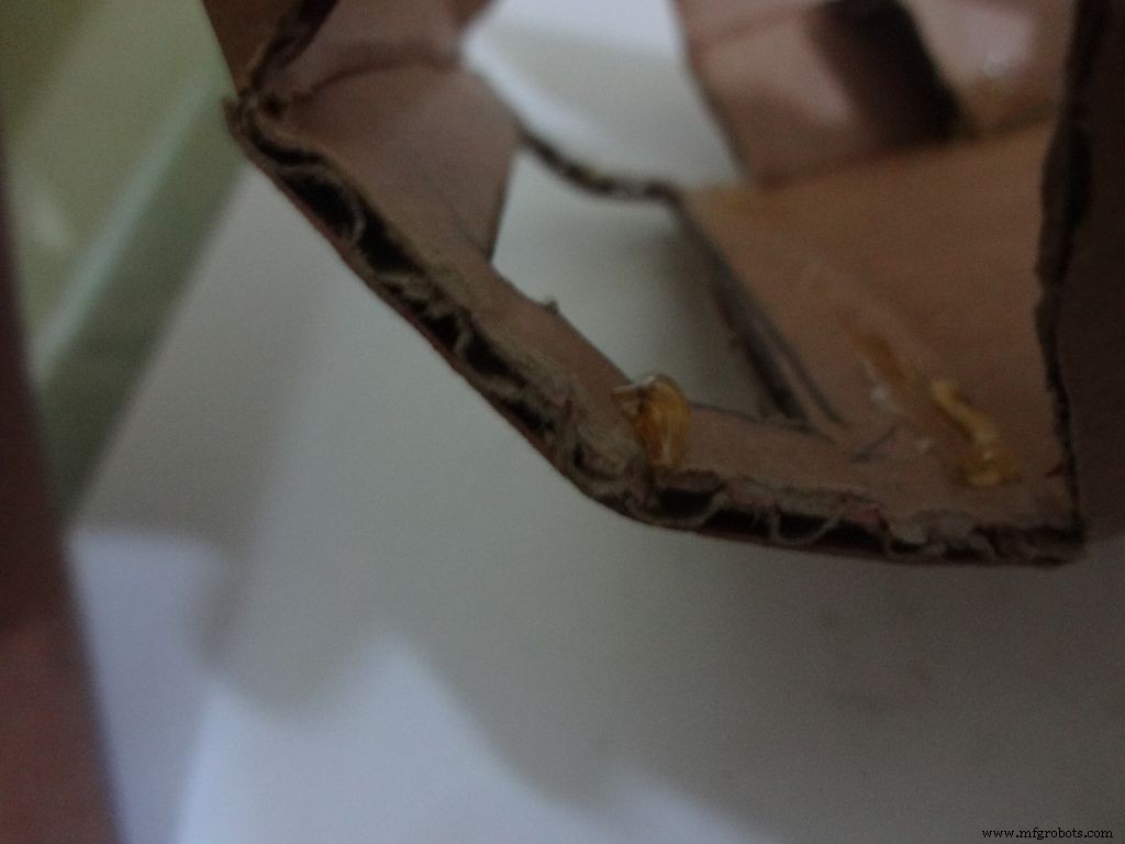
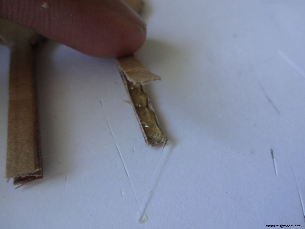
À l'aide du papier de verre, poncez les quatre premiers bords en pente, appliquez de la colle chaude avec un pistolet à colle (un côté à la fois), joignez et maintenez 30 à 60 secondes pendant que la colle refroidit.
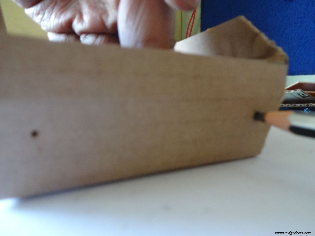
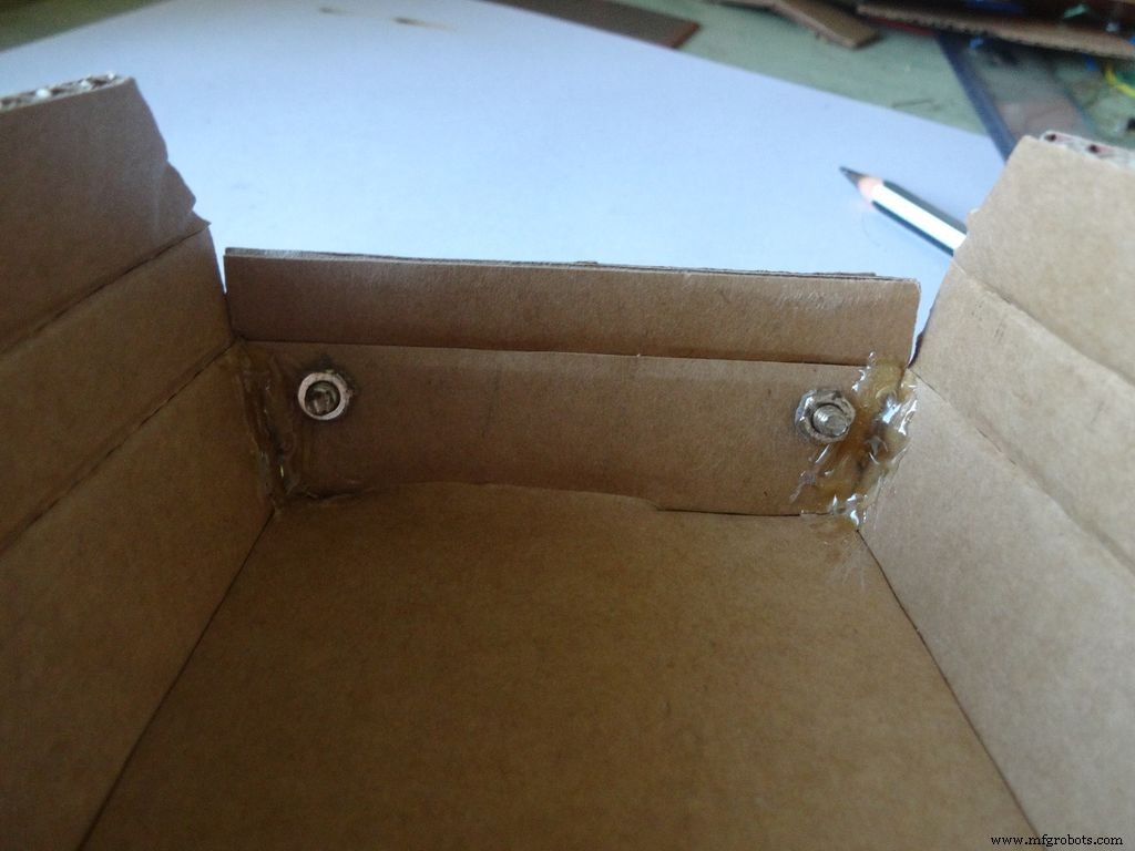
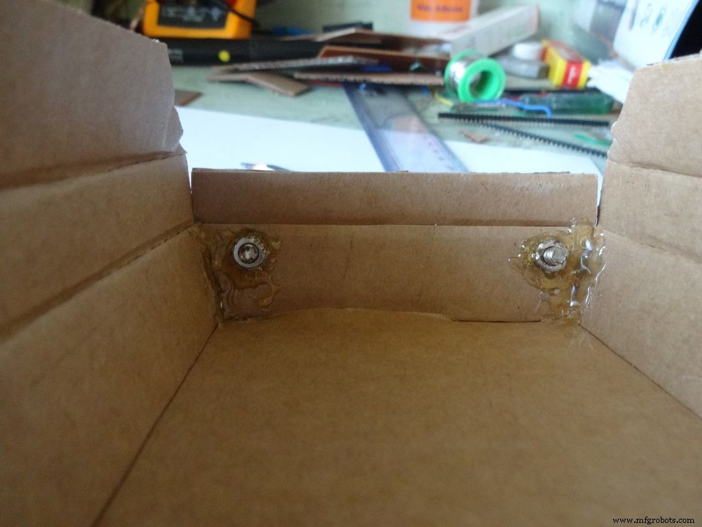
Faites deux trous avec une épingle comme indiqué et agrandissez-le avec un crayon juste assez pour insérer le boulon. Serrez l'écrou à l'intérieur, appliquez de la colle chaude (juste sur l'écrou !), laissez refroidir. Retirez le boulon avec un tournevis.
Ensuite, repliez les deux rabats latéraux vers l'intérieur et collez-le. La partie extérieure du rabat doit être légèrement inclinée et la partie médiane plate.
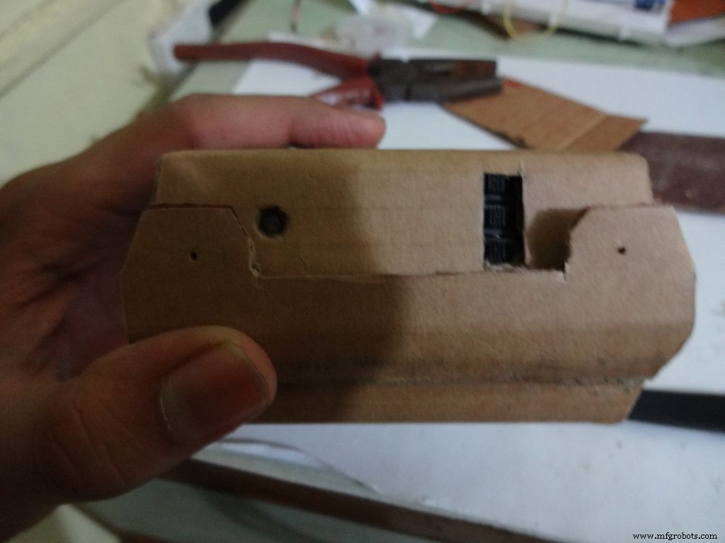
Étape 10 :Fabrication du boîtier - Ajout des interrupteurs
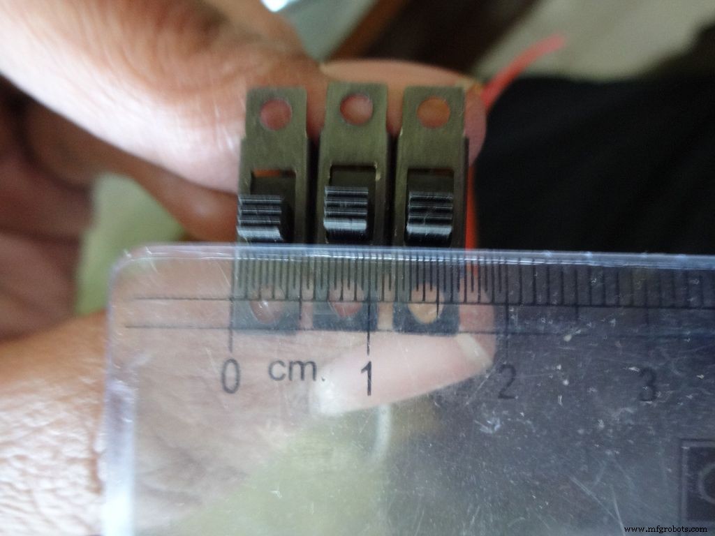
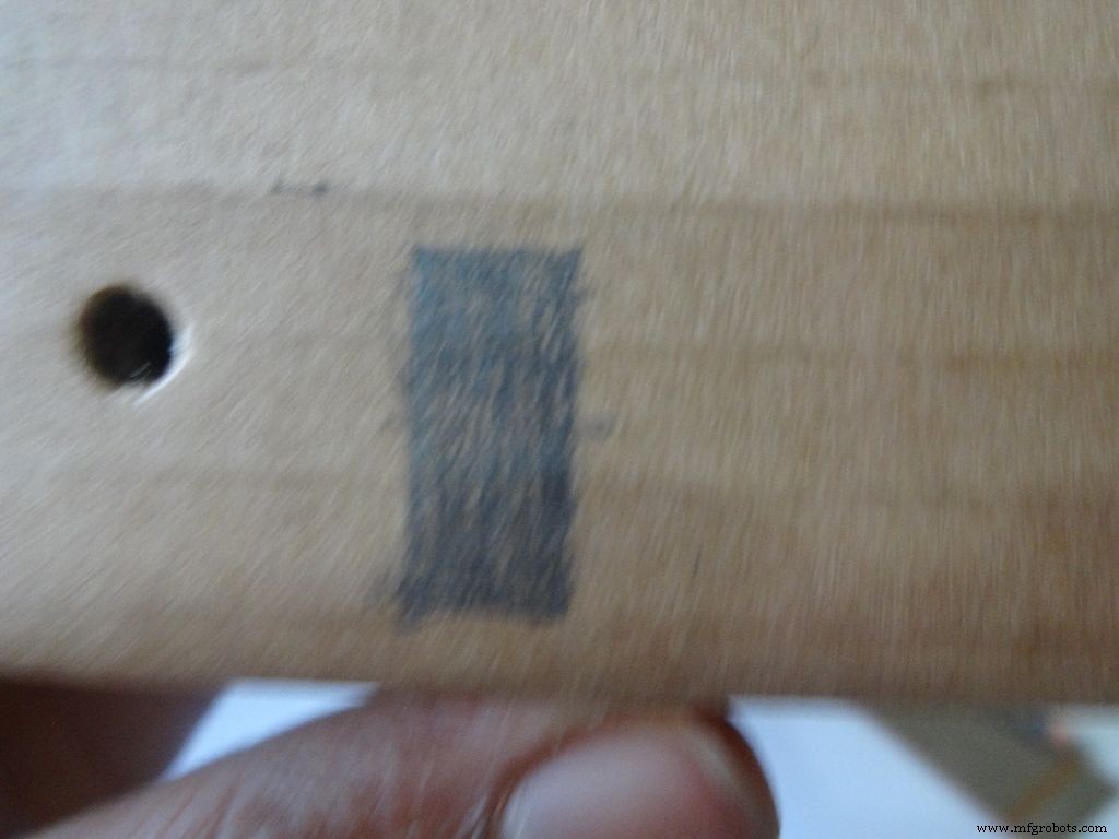
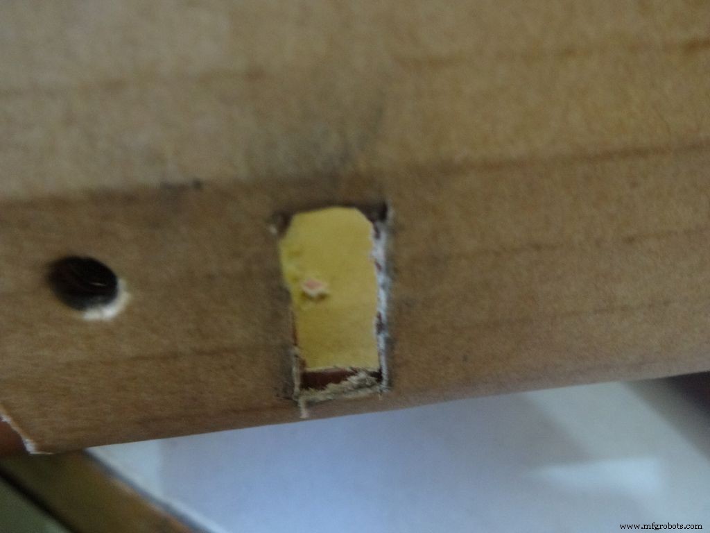
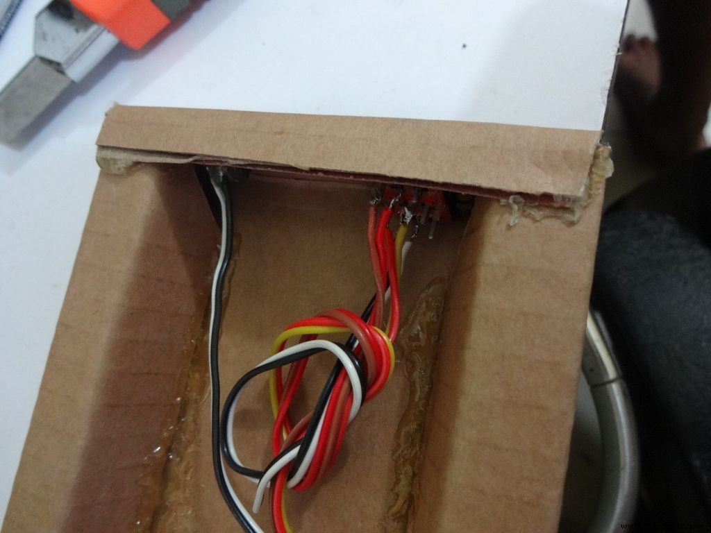
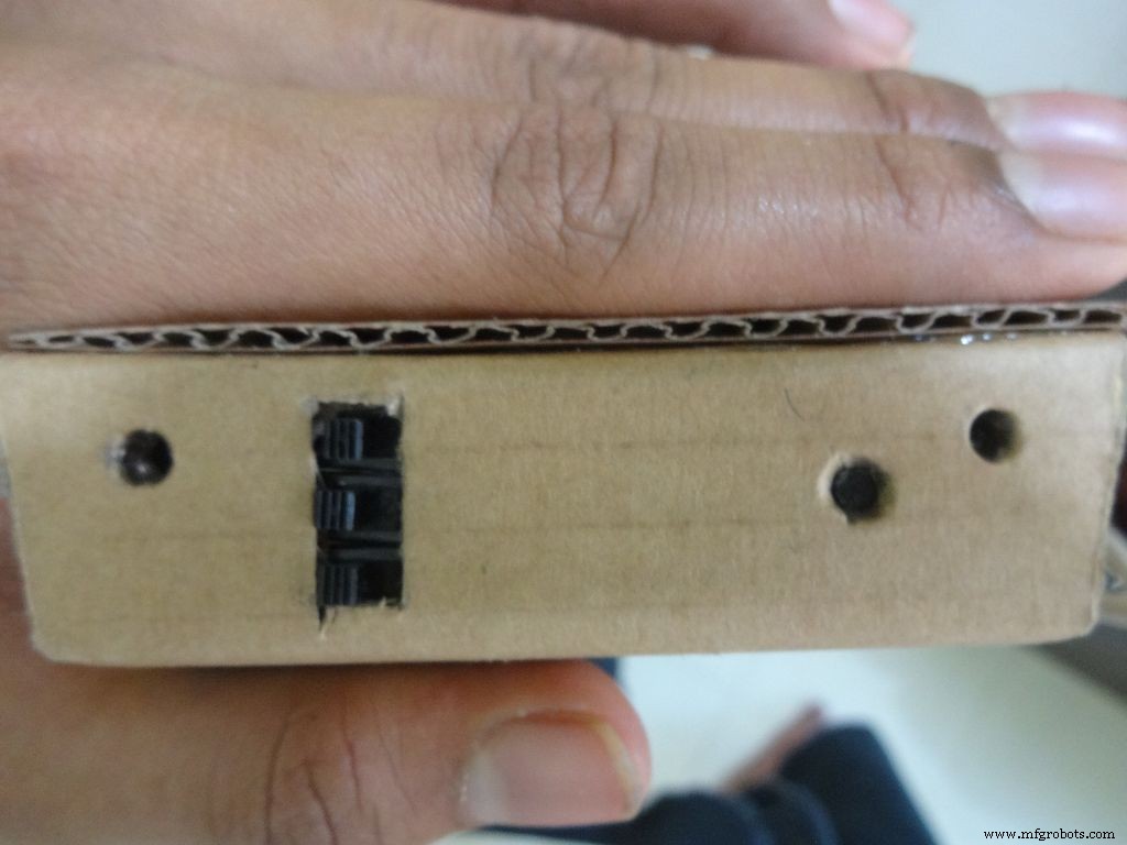

Take the 3 sliding switches with wires we soldered earlier, measure the approximate dimension of rectangle needed. Mark it on the left side of the box(left from the outside). Cut it with a cutter, sand it a bit on the inside to remove any material sticking out.
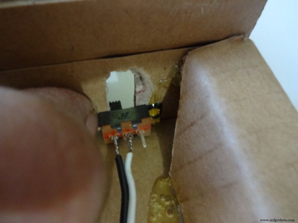
Keep the first switch in position and while holding it add glue on one side. Let it cool. Repeat with the other two as well, and then add glue on the remaining sides. Note:The wired pins of the switches should be on the same side.
Make another hole on the other side for the reset pushbutton. Hold the button in place and add glue. Fold the lower flap inwards and stick it.
Step 11:Making the case - Top half or cover
Sand the edges and stick the side flaps inwards(just like the base) for the top half
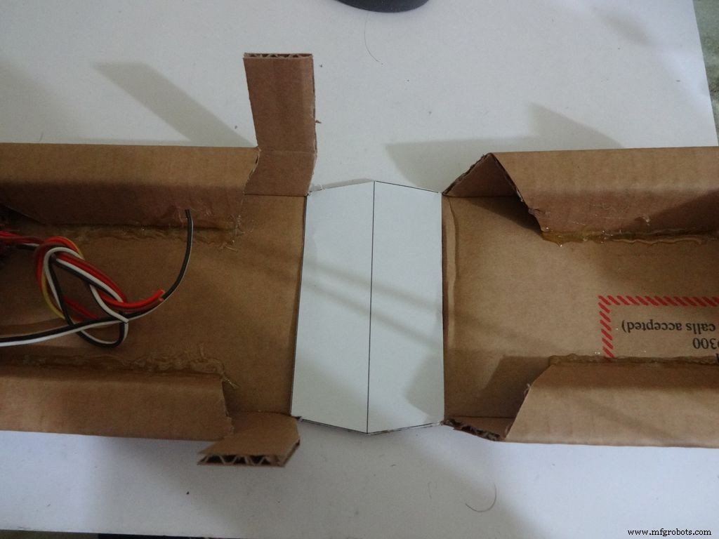
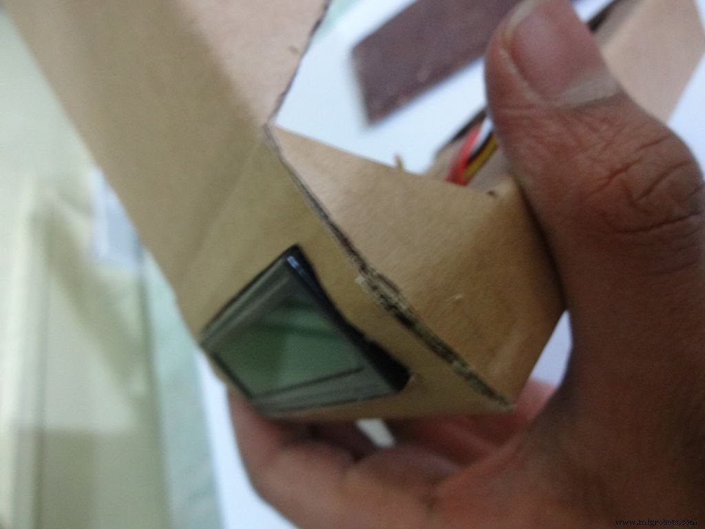
Step 12:Making the case - Adding the LCD
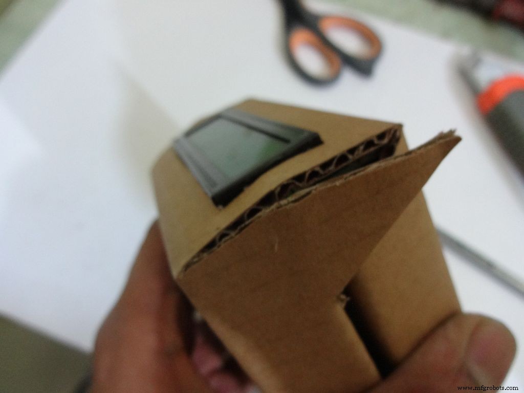
Crease the middle line. (Didn't do it earlier as it is delicate and gets loose soon).
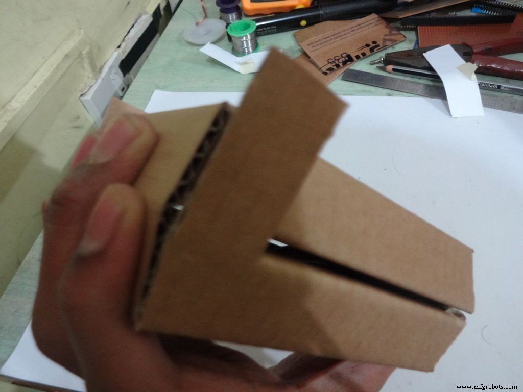
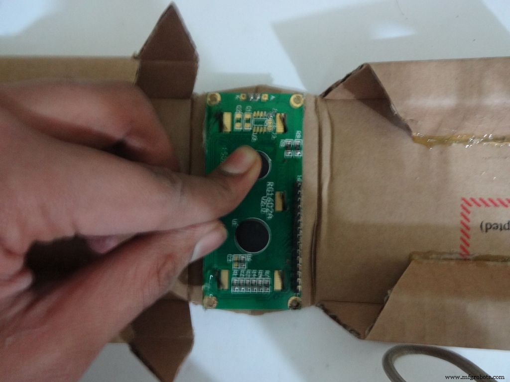
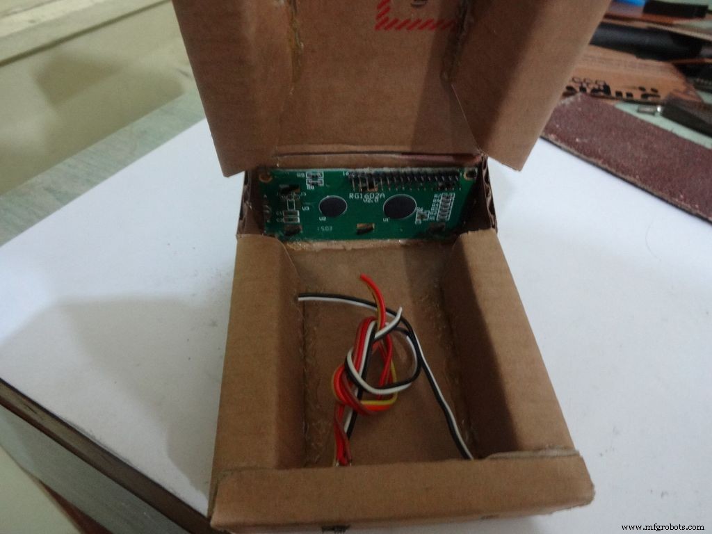
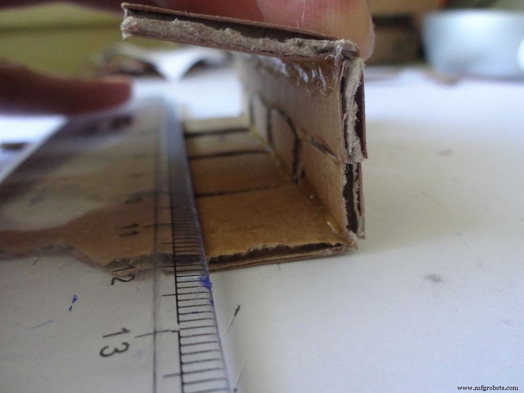
Fold the cover over to the base and check whether everything looks alright, sufficient spacing should be left for the IC pins. (See photo)
Cut the covering flaps as shown in the images.
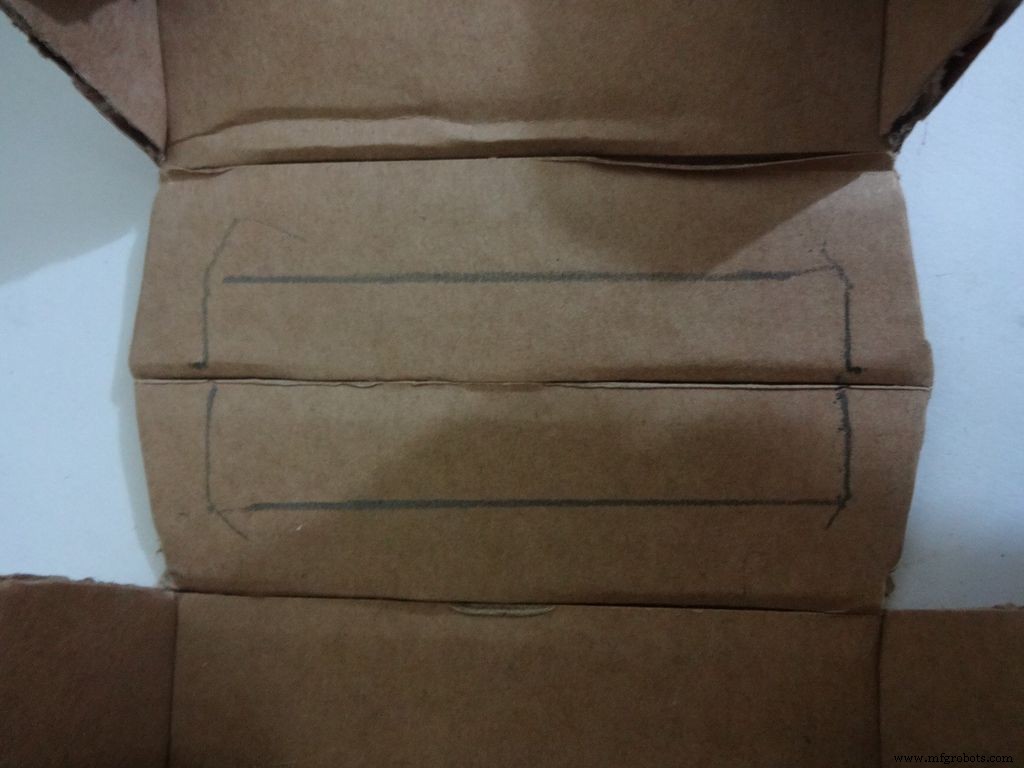
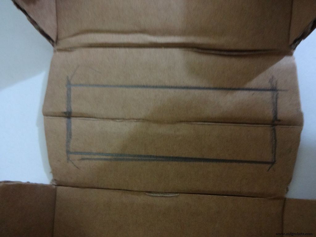
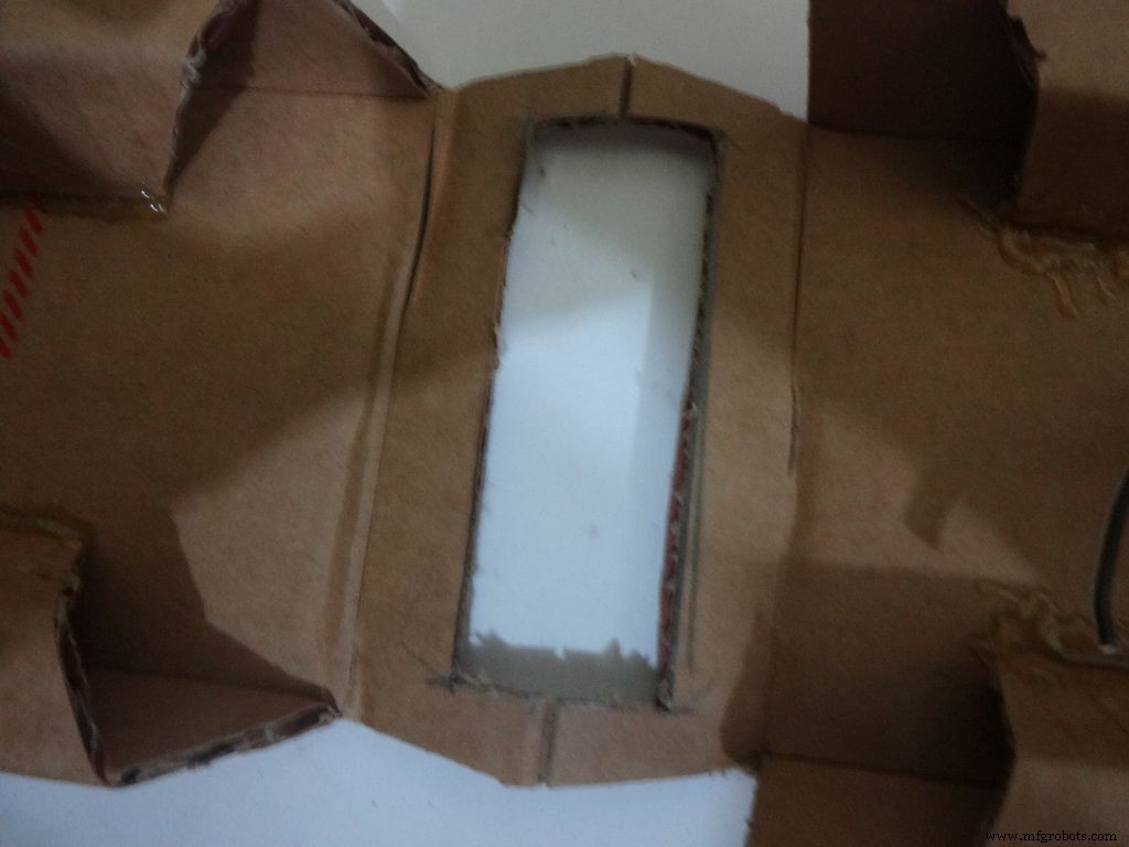
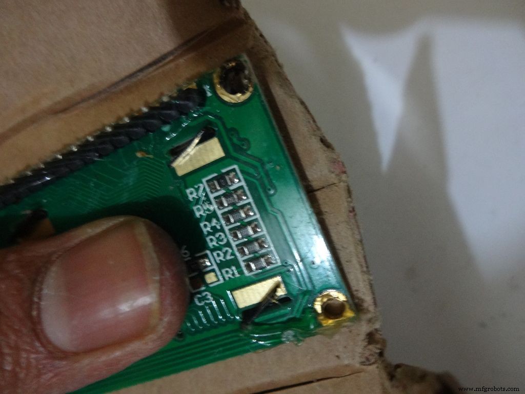
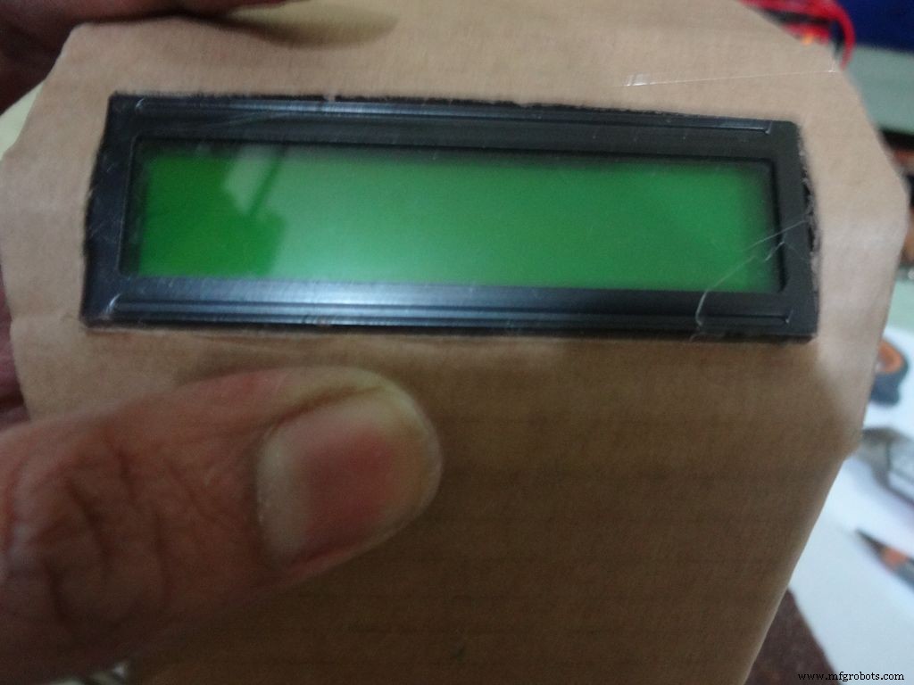
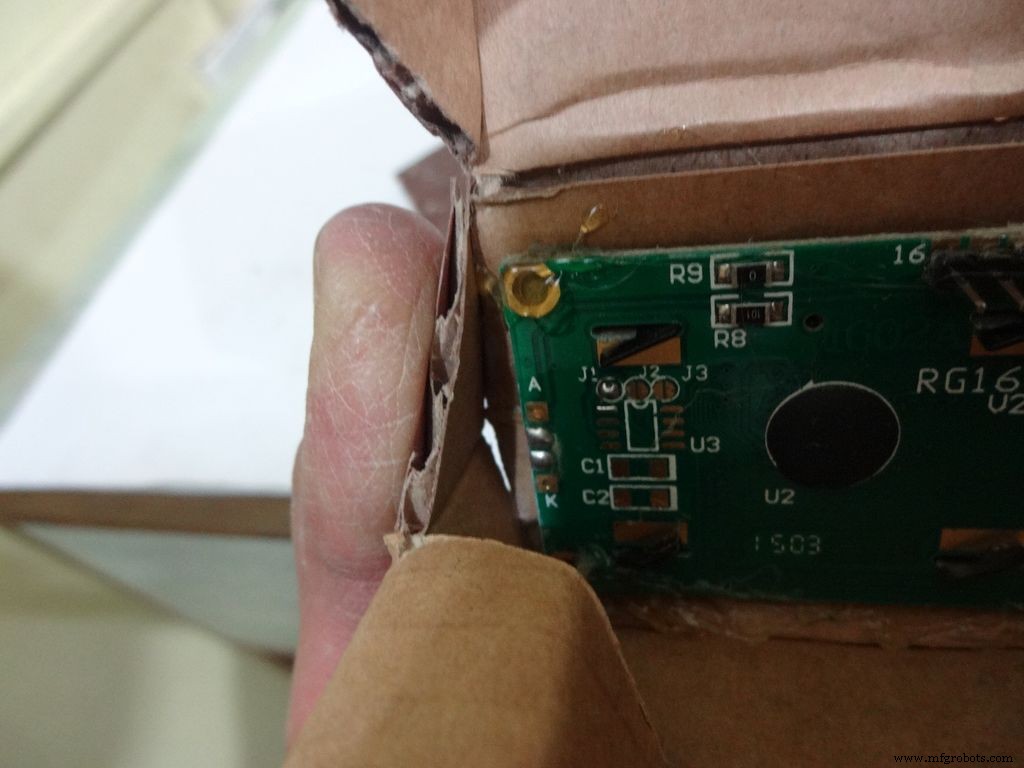
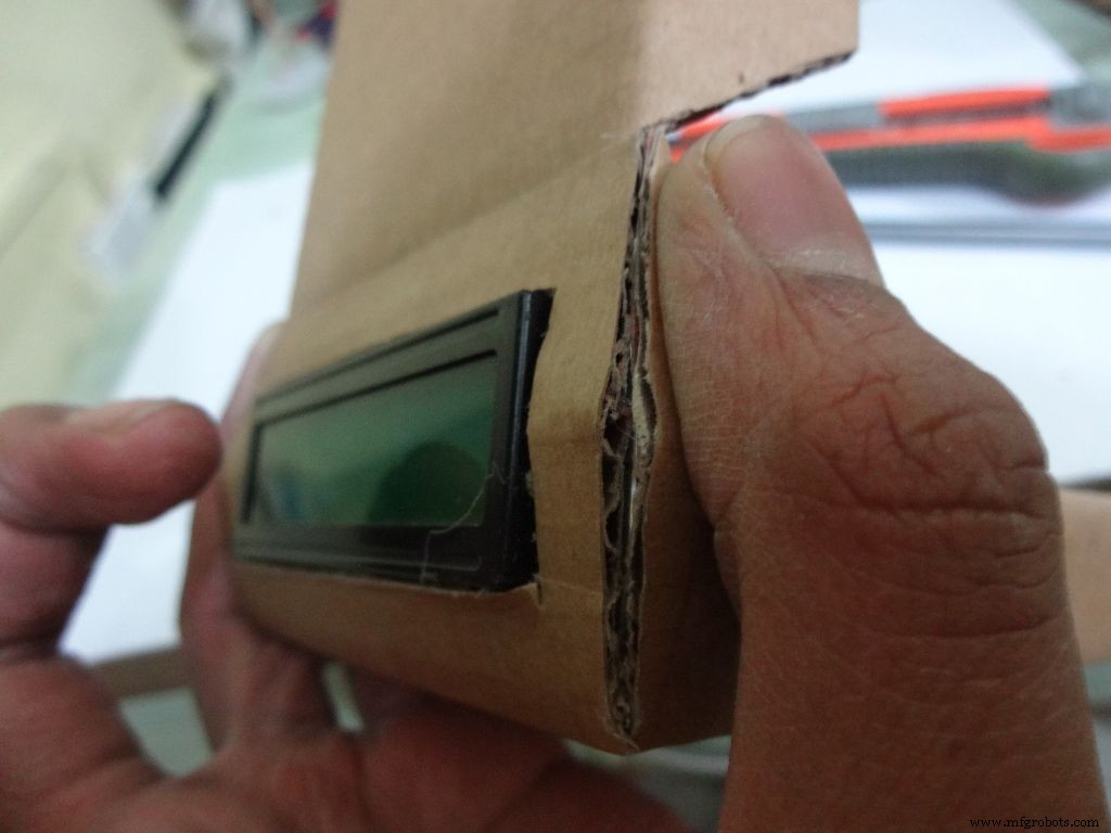
Keep the LCD at the center of the LCD Area, mark it with a pencil. Using a ruler, make the rectangle properly and cut it carefully using a cutter. Fold the LCD window and apply glue to the hinges to keep them at their correct position. Insert the LCD and make any modifications if required.
Finally, apply glue to the four corners(don't put excess) of the LCD and place it in position.
Step 13:Making the case - Final flaps
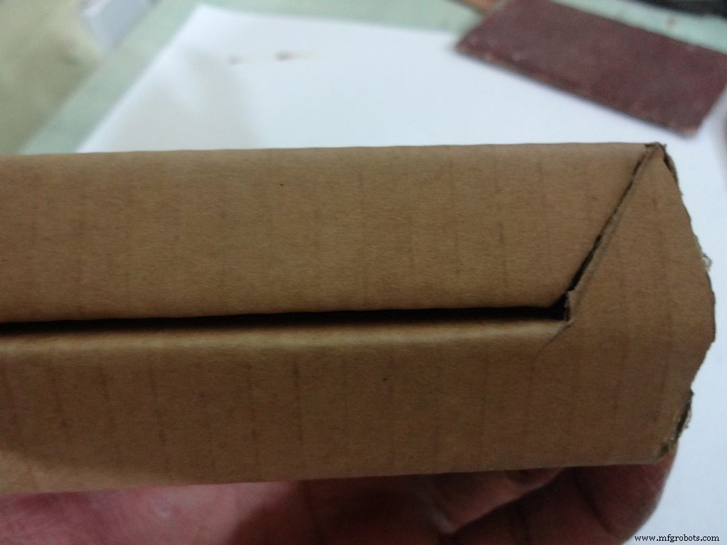
Sand, trim and close the tringular flap.
Make a small piece as shown and stick it to the cover. Make two holes, widen them with a pencil for inserting the bolt and locking the cover to the base.
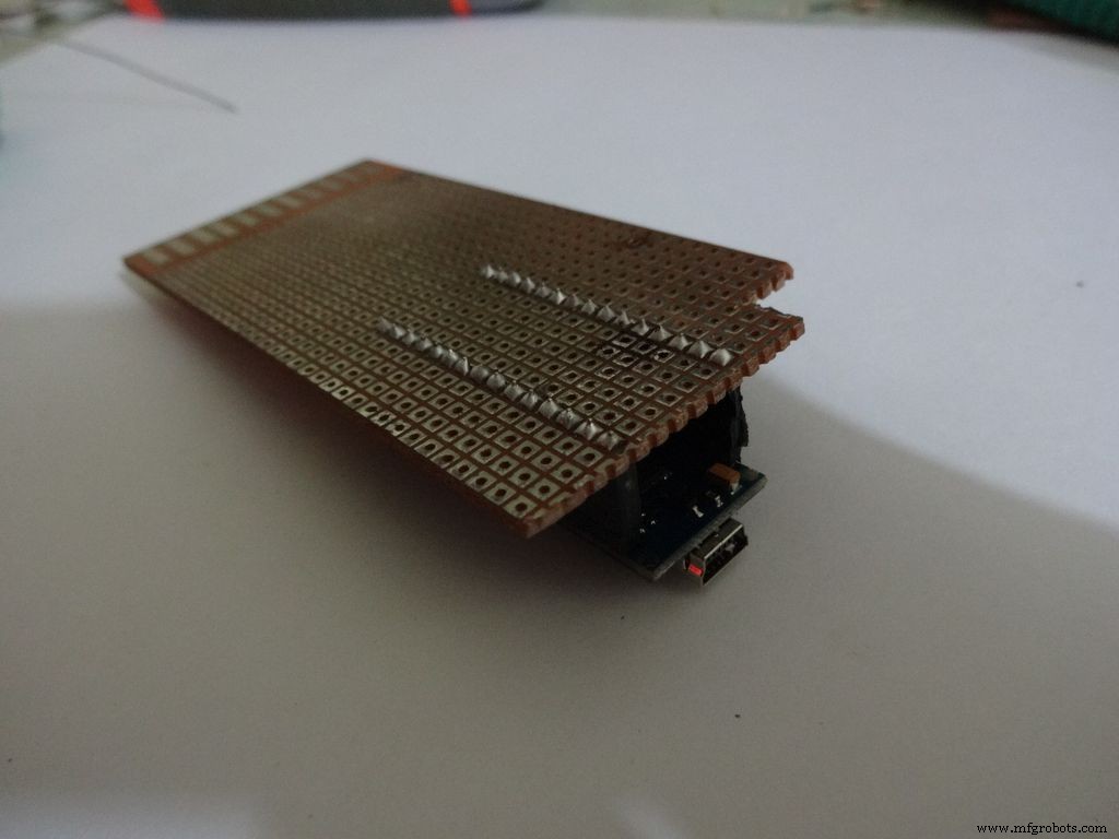
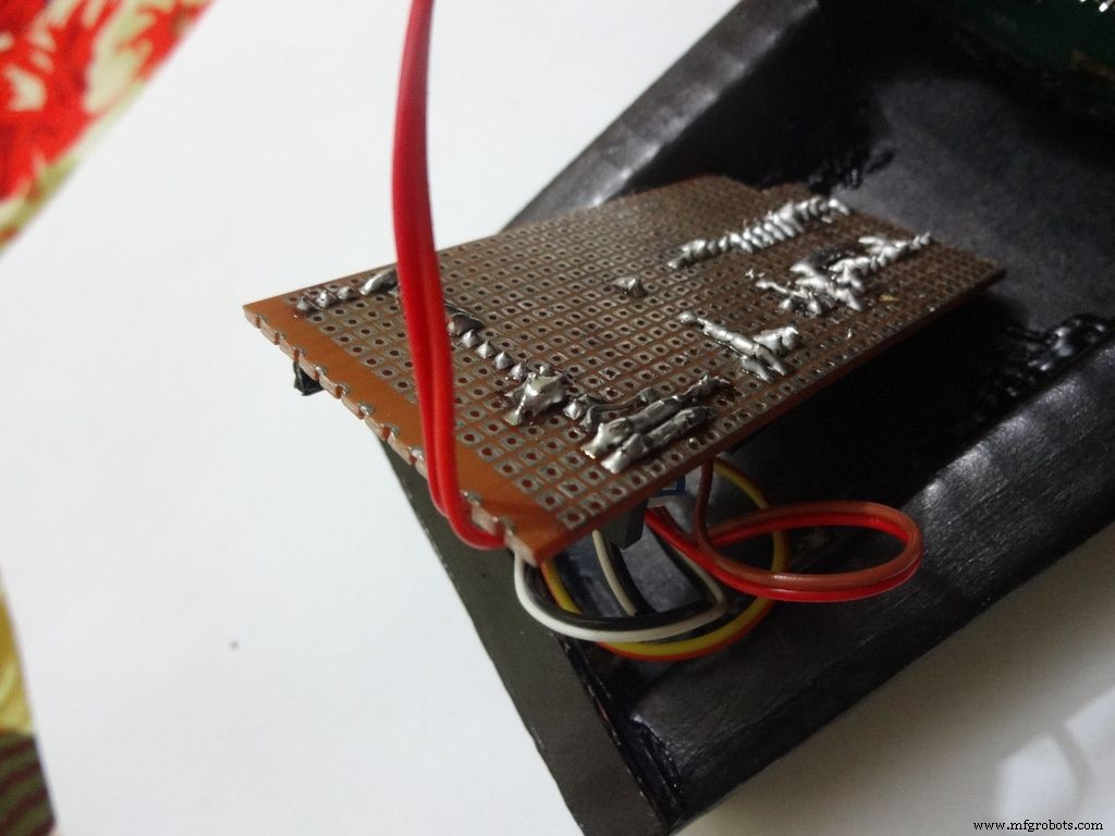
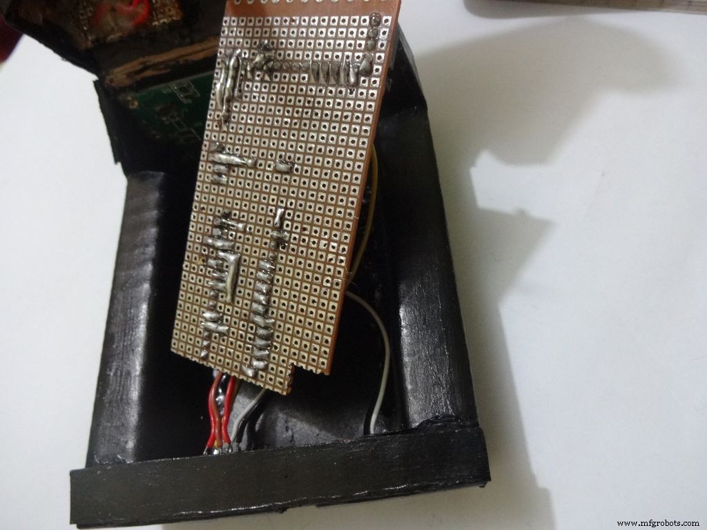
Step 14:The Circuit Board -- Making it fit

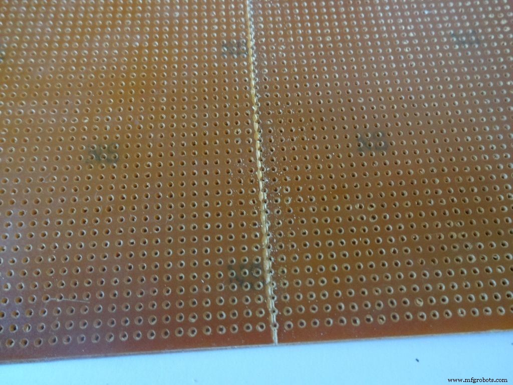
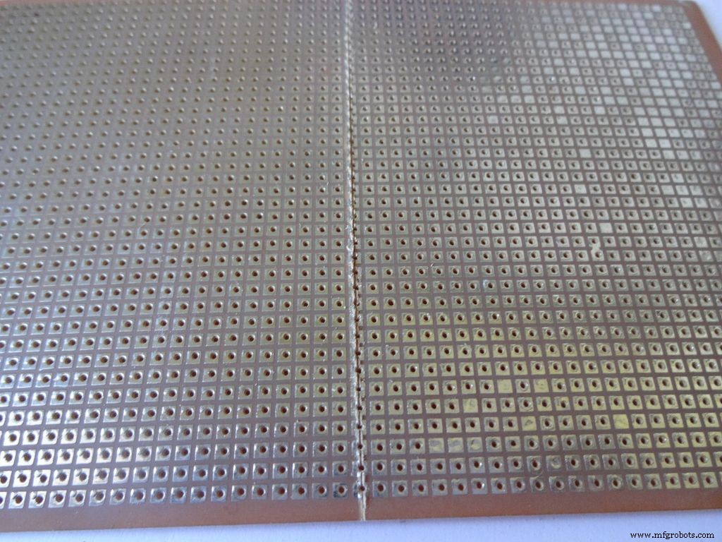
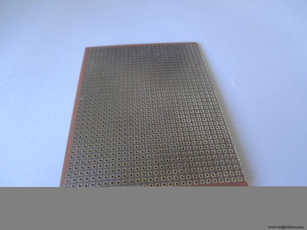
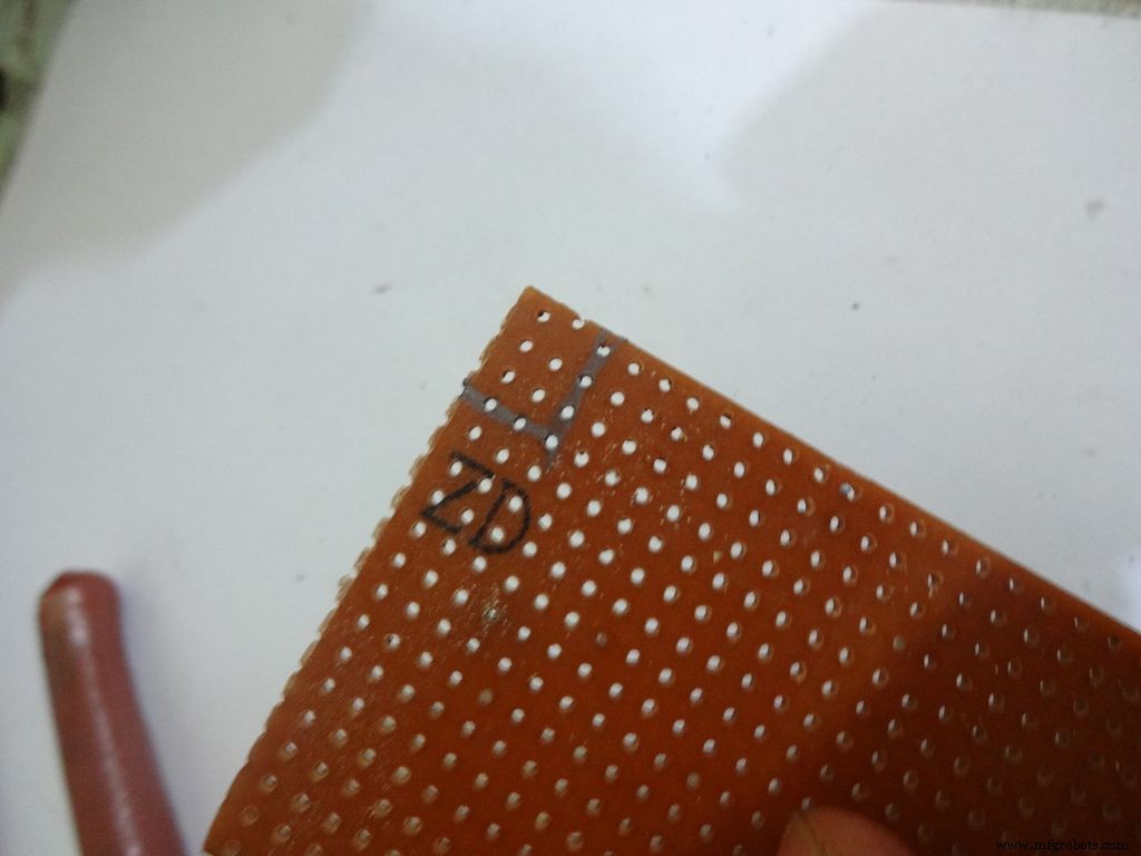
Cut the General purpose PCB to the right size such that it fits properly in the case. Mine is 2x4inches. To cut it, use the ruler and cutter and swipe it multiple times on both sides and it breaks off easily then.
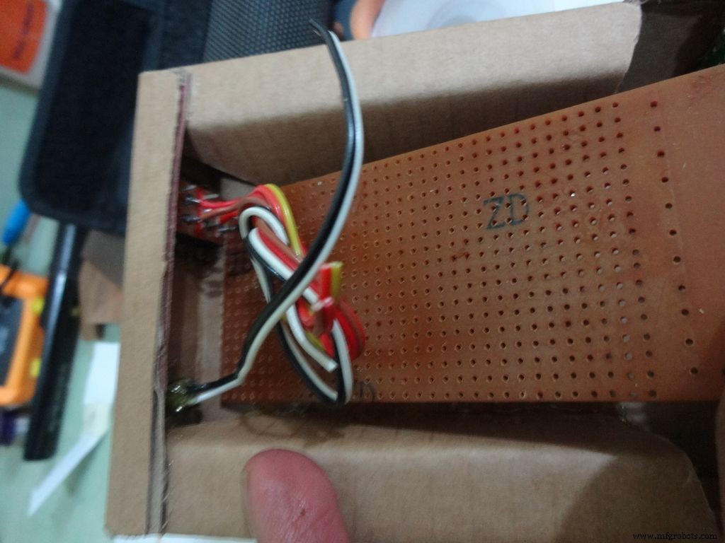
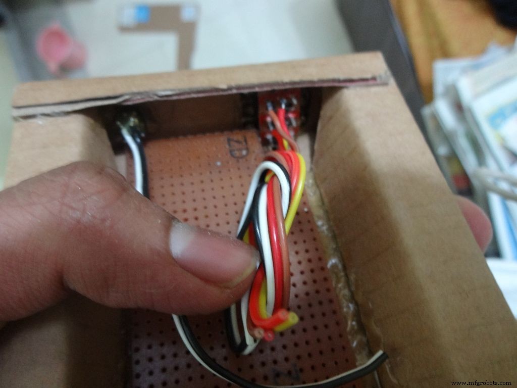
Place it inside. If the glue from the side flap lifts the PCB up, reheat the glue to flatten it or lessen the size of PCB a bit.
Cut a small part so that the 3 switches fit in and PCB goes entirely inside.
Step 15:The Circuit Board -- Arduino Nano

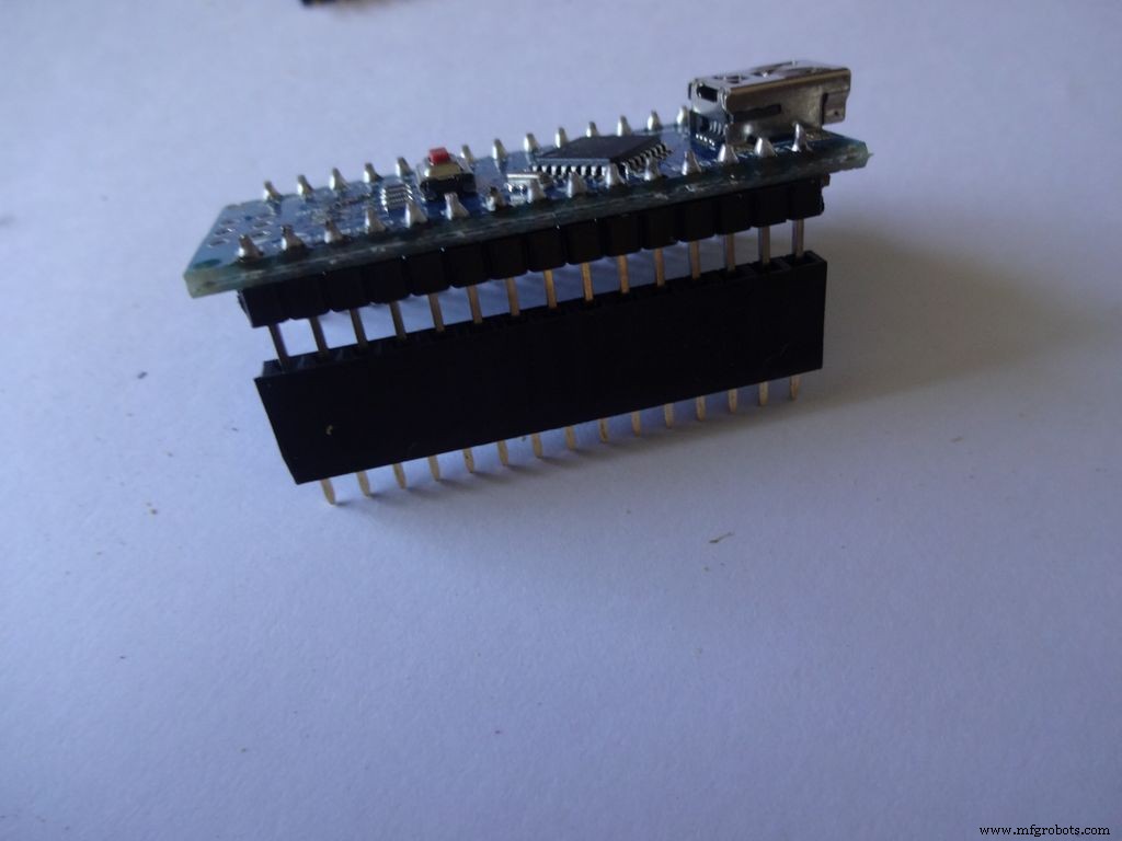
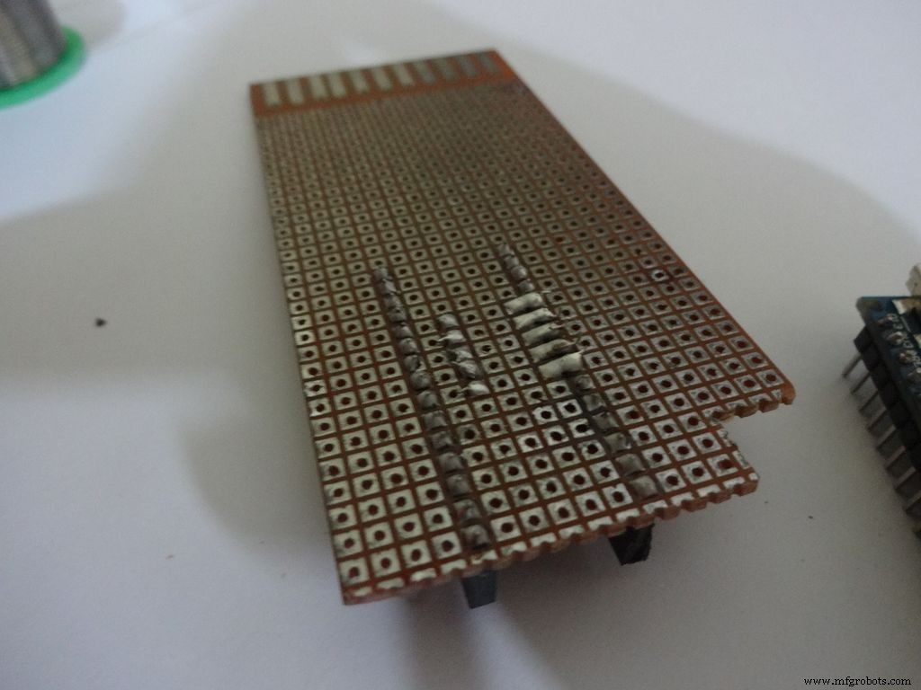
Cut female header pins of the right size for the Arduino.
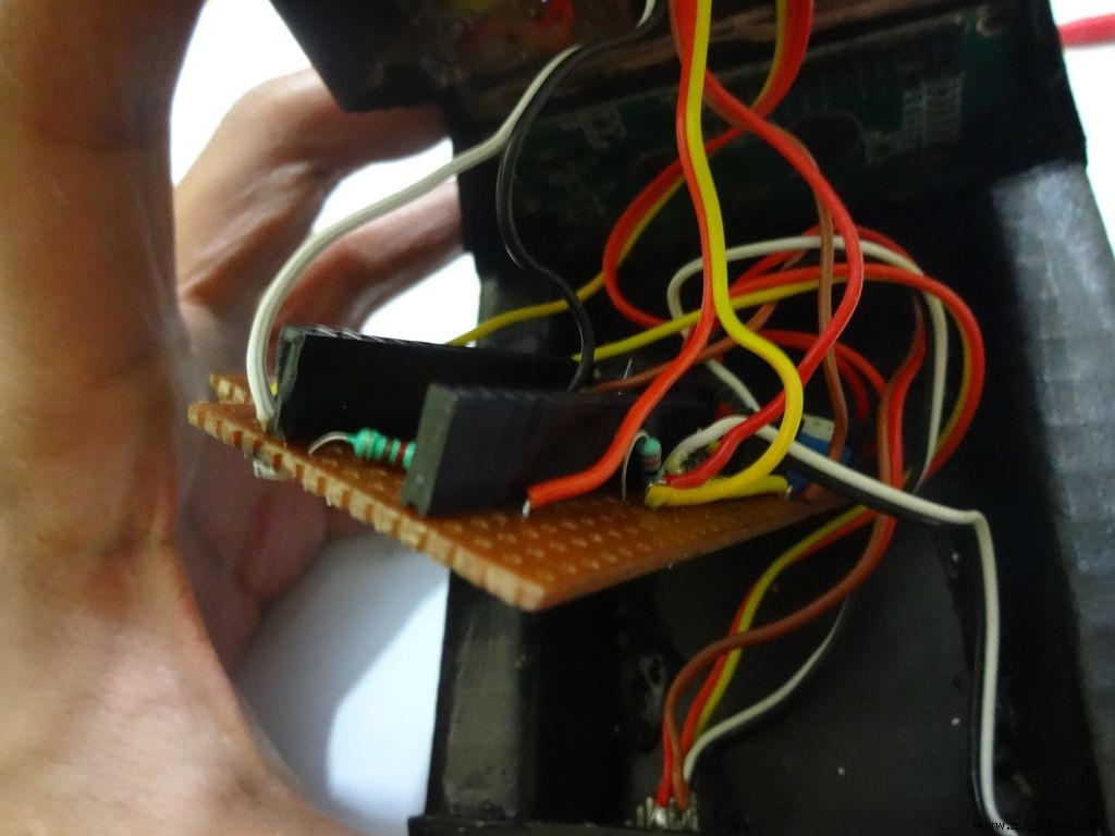
Place it at the center edge of the PCB and solder all the pins.
Step 16:The Circuit Board -- Ohmmeter
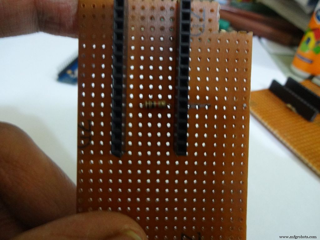
Before making any connections on the PCB please double check from the final Circuit Design.
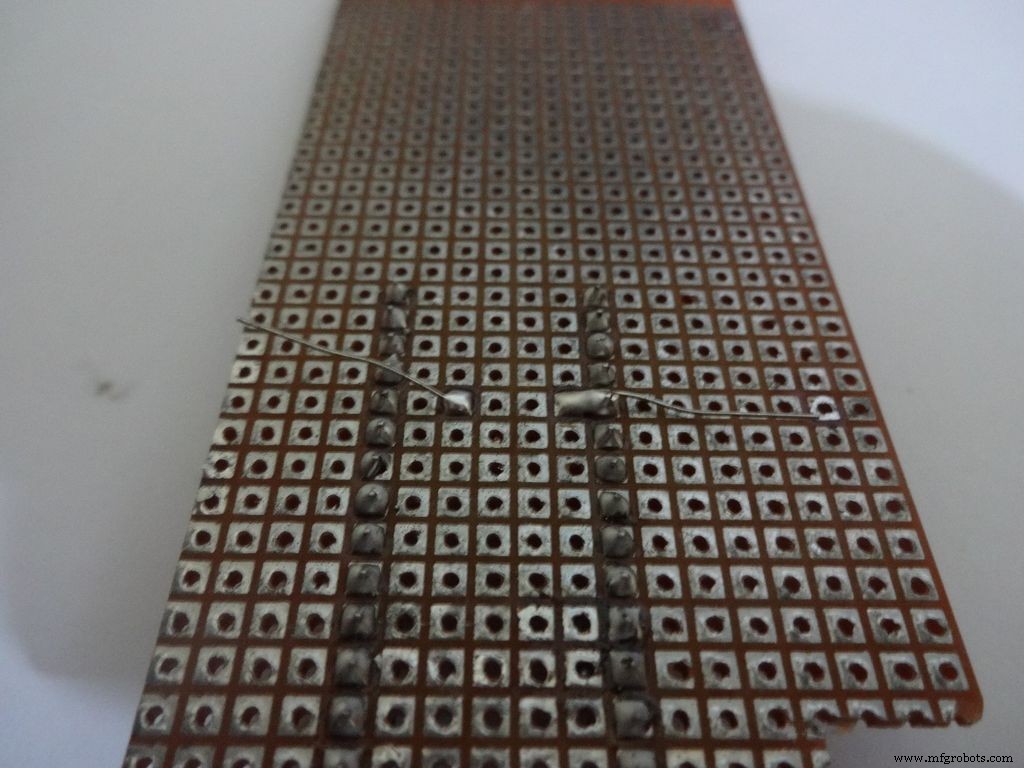
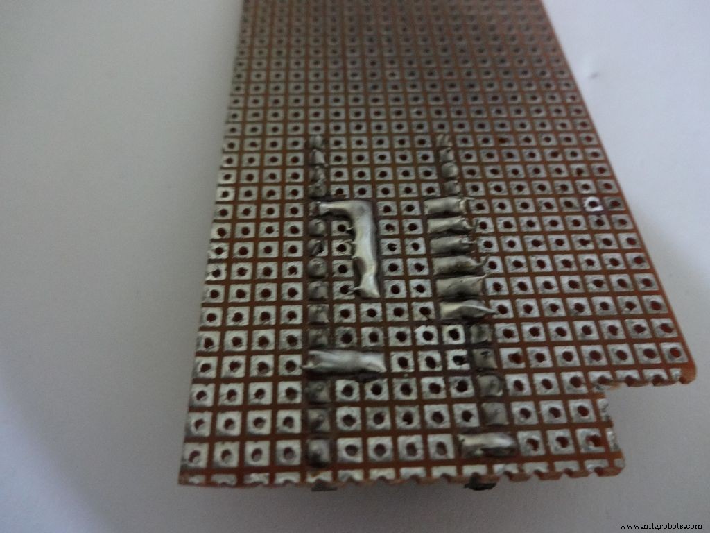
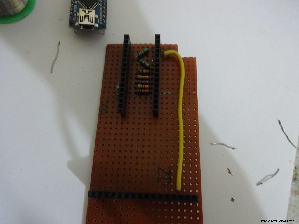
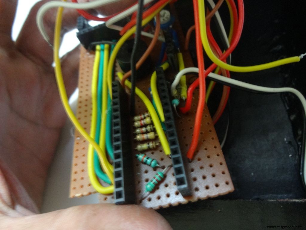
For the ohmmeter start by adding a 1k Ohm resistor to pin D2 of arduino. Place the arduino and carefully mark the pin. On the reverse side, bend as shown and solder it.
Do the same with the other 4 resistors, 4.7k, 10k, 47k and 100k Ohm.
Note:keeping all the tolerance bands(gold band) on one side is a good practice, eg UP and RIGHT.
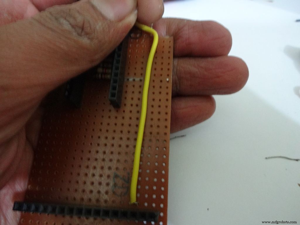
Combine the second ends of resistors and solder it to A7 .
Step 17:The Circuit Board -- Capacitance Meter and Diode Test
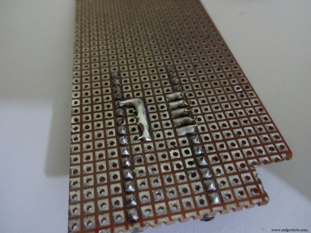
Capacitance Meter:
Solder a 220 Ohm resistor from D12 to A0 . And a 10k Ohm resistor from A0 to D7 .
Note: D7 (digital pin) is also used for LCD data pin D4 .
Diode Test:
Solder the 10k Ohm pullup resistor from A6 to +5V .
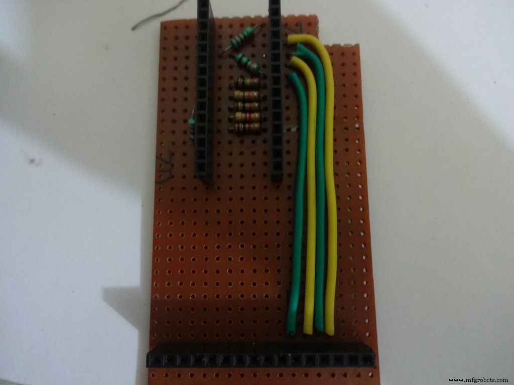
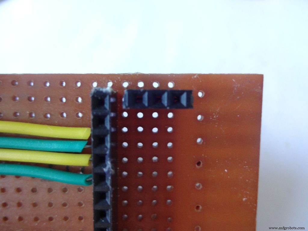
Step 18:Making connectors for LCD
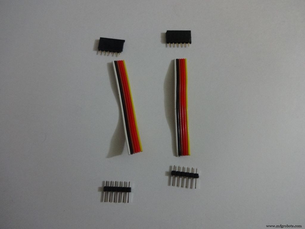
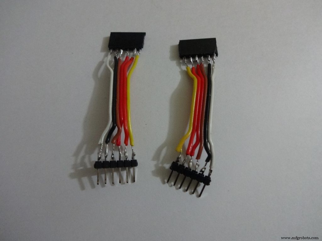
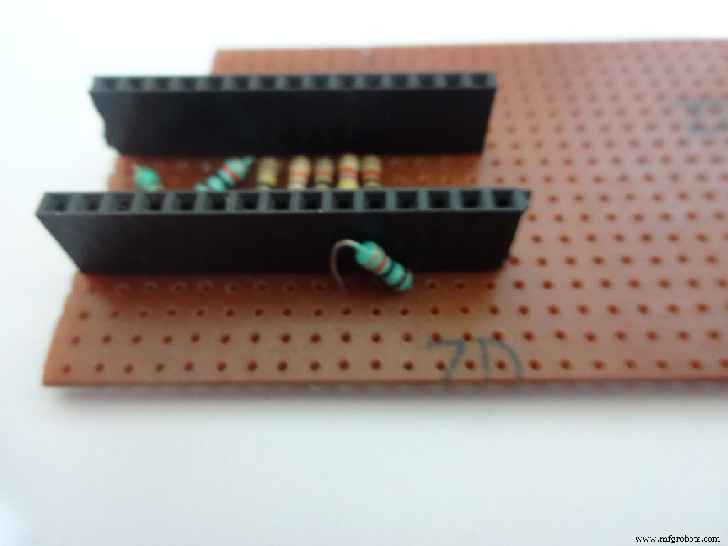
We just use the first 6 and last 6 pins on the LCD. Pins D0-D3 are unused. So we will be making connectors for only the used pins. It is recommended that you do the same because plugging/unplugging a 16pin connector becomes very tough once the build is complete.
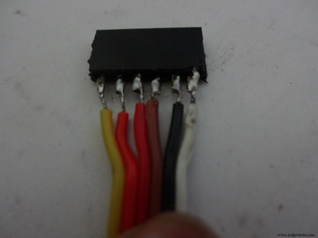
Cut 2x 6pin female and male header pins. Also take 6 wire ribbon cable, around 2-2.5 inches long.
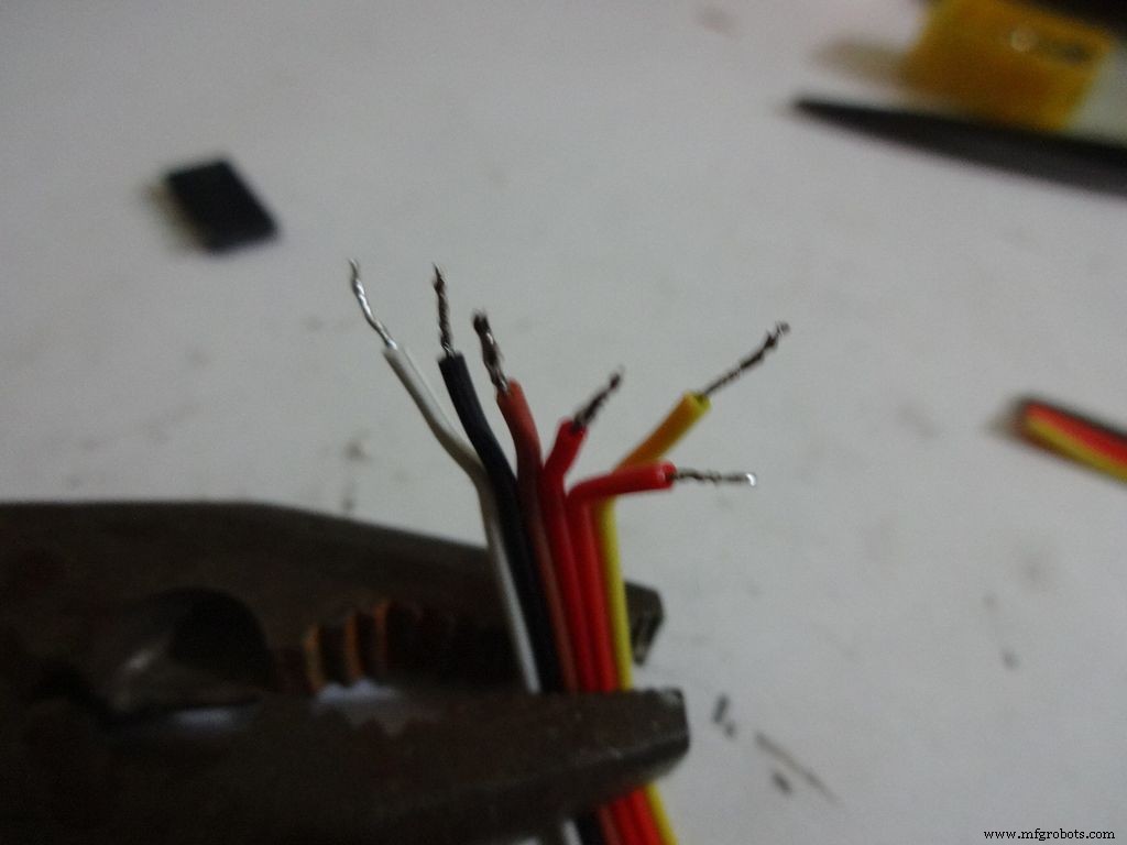
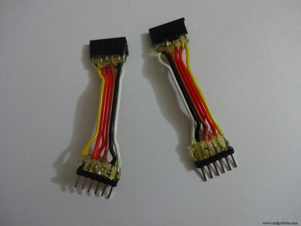
Strip the insulation and tin the leads. Also tin the header pins. Join them one by one just like the slide switches.
Apply hot glue to secure the wires.
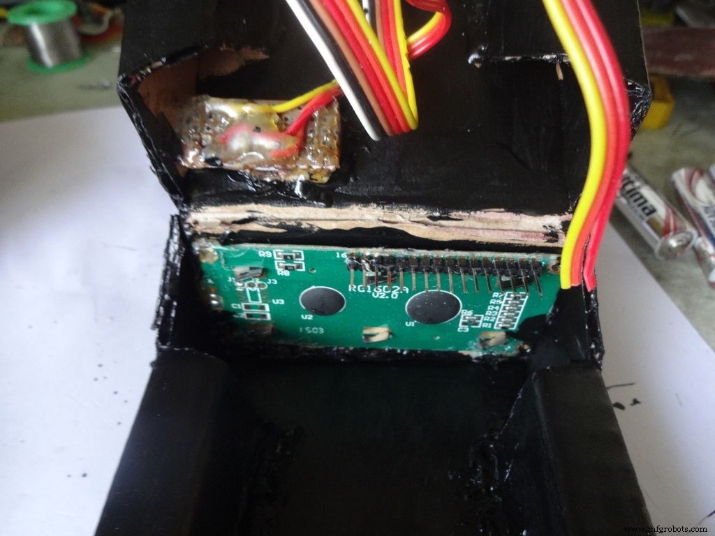
Step 19:The Circuit Board -- LCD connections
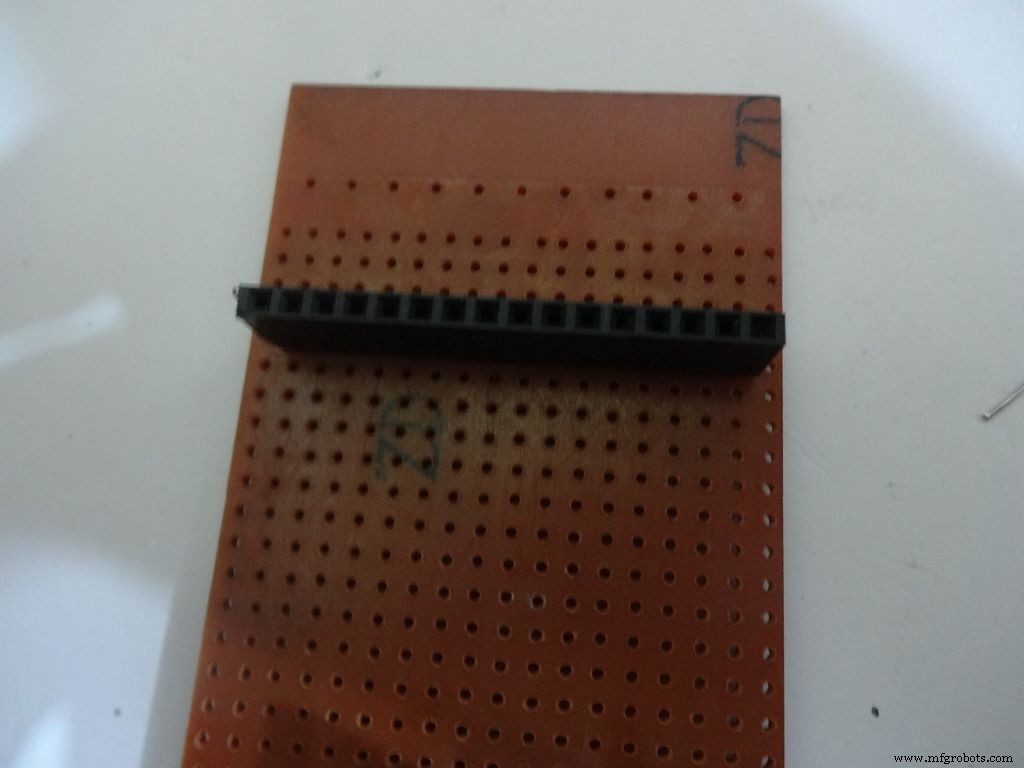
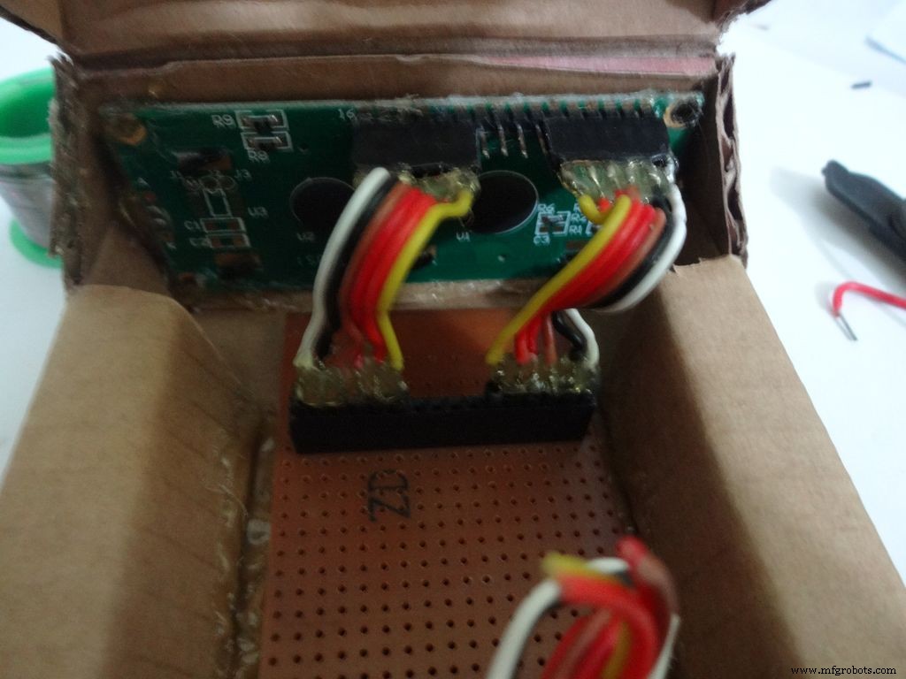

Place the PCB inside the case. Plug the connector to LCD and see where the female port should be on the PCB, solder it.
Make sure you leave 4-5 dot rows behind the LCD port. The Power switch will be added here later.
Measure the length of single stranded wire needed to connect data pins (D4 , D5 , D6 and D7 ) on the LCD to digital pins( D7 , D8 , D9 and D10 ) on the Arduino, respectively.
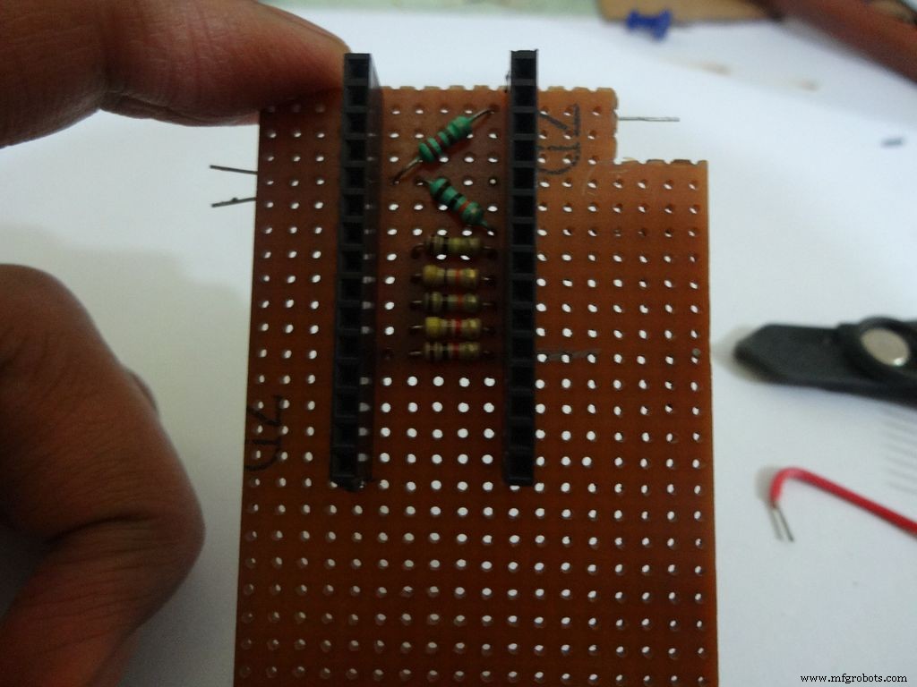
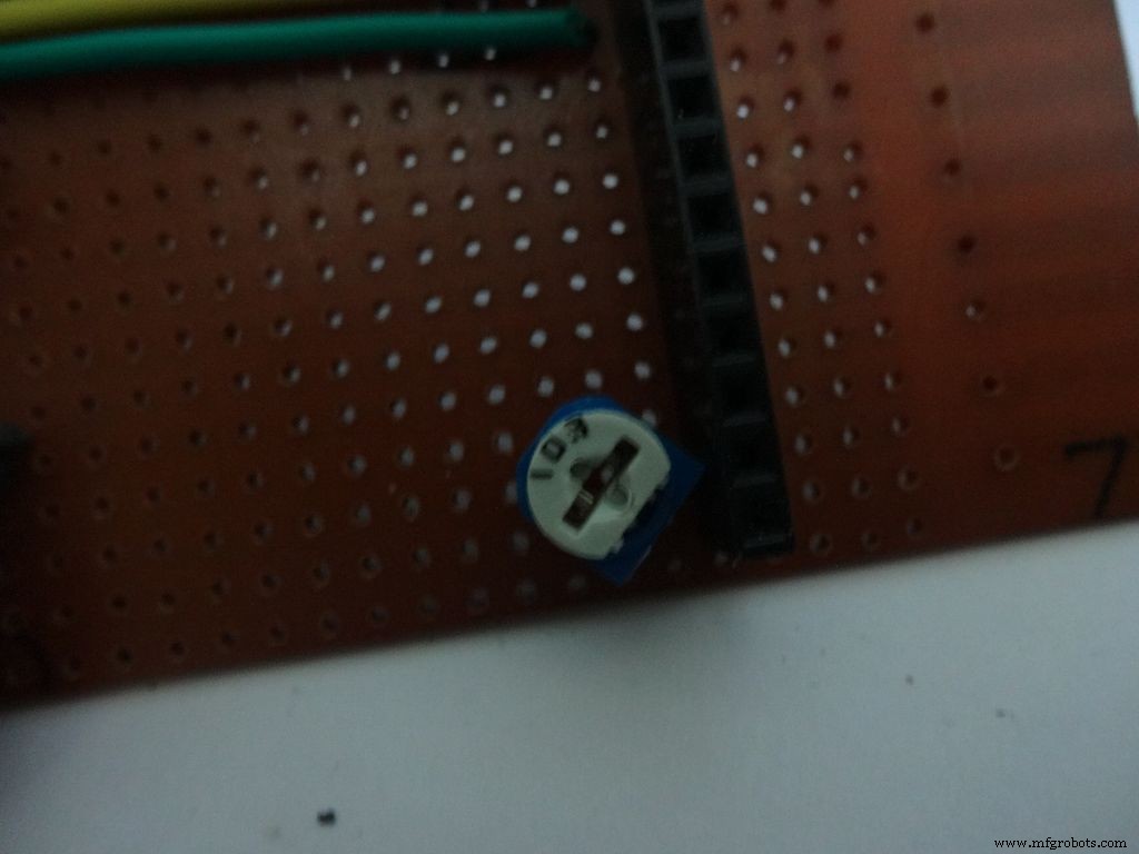
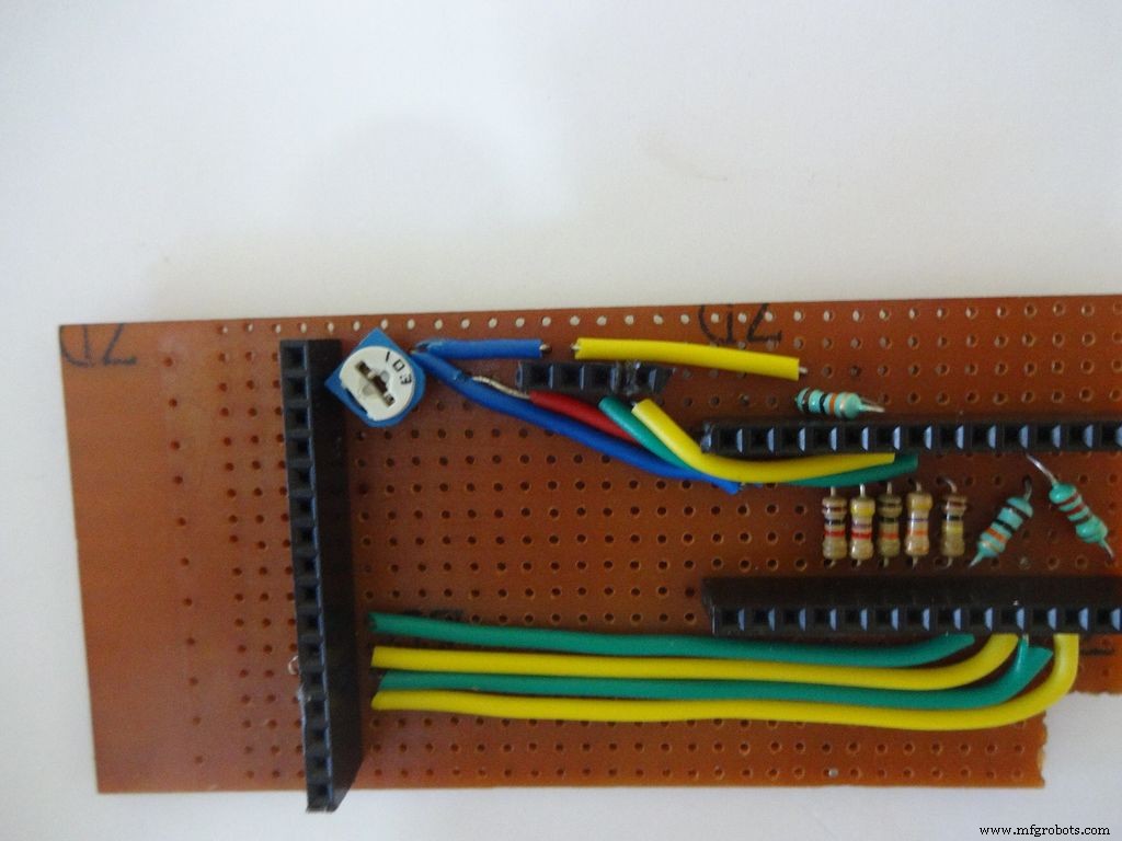
Add the 10k ohm potentiometer such that the side ends go to Vcc , GND and the middle pin to V0 .
Connect Vss(GND) on the LCD to GND , and Vdd to +5V . Also connect R/W to GND .
Arduino Pin
LCD
D7 D4 D8 D5 D9 D6 D10 D7 GND Vss(GND) +5V Vdd
Step 20:The Circuit Board -- RTC Module
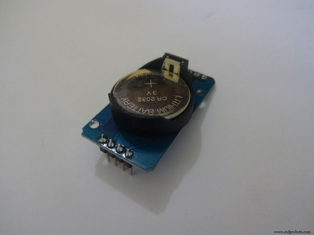
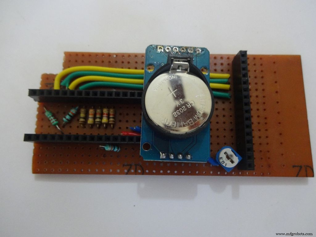
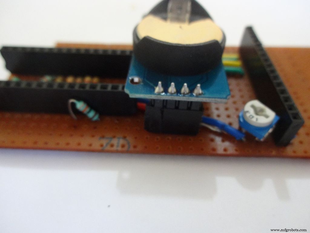
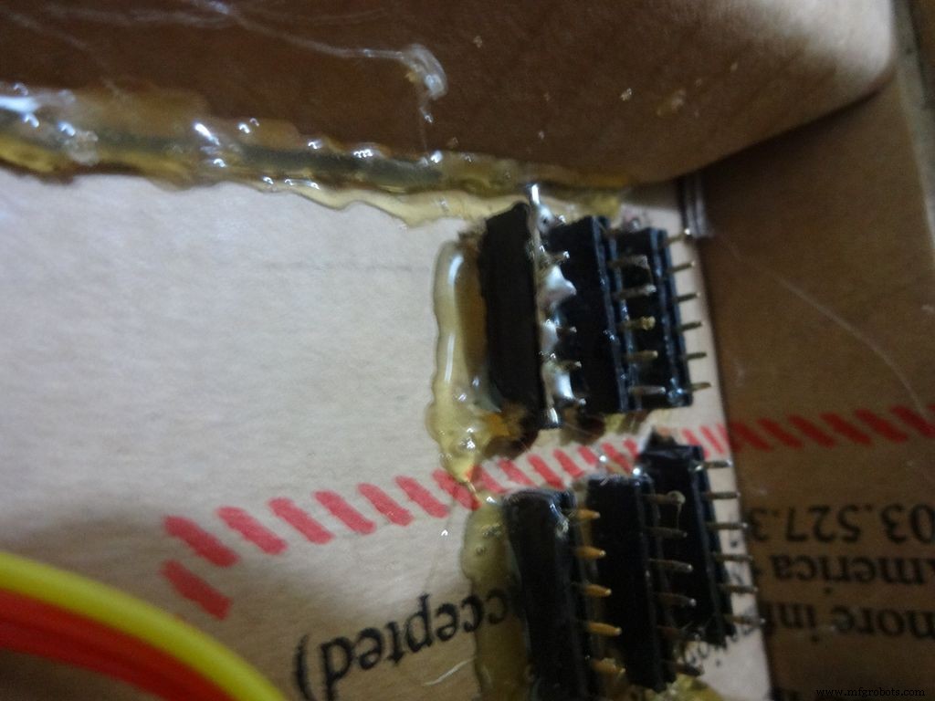
I desoldered the default 90 degree header pins on the module and added straight ones so that it fits flat on the PCB.
Solder 4pin female header pin and make connections to Vcc , GND , SDA to A4 and SCL to A5 .
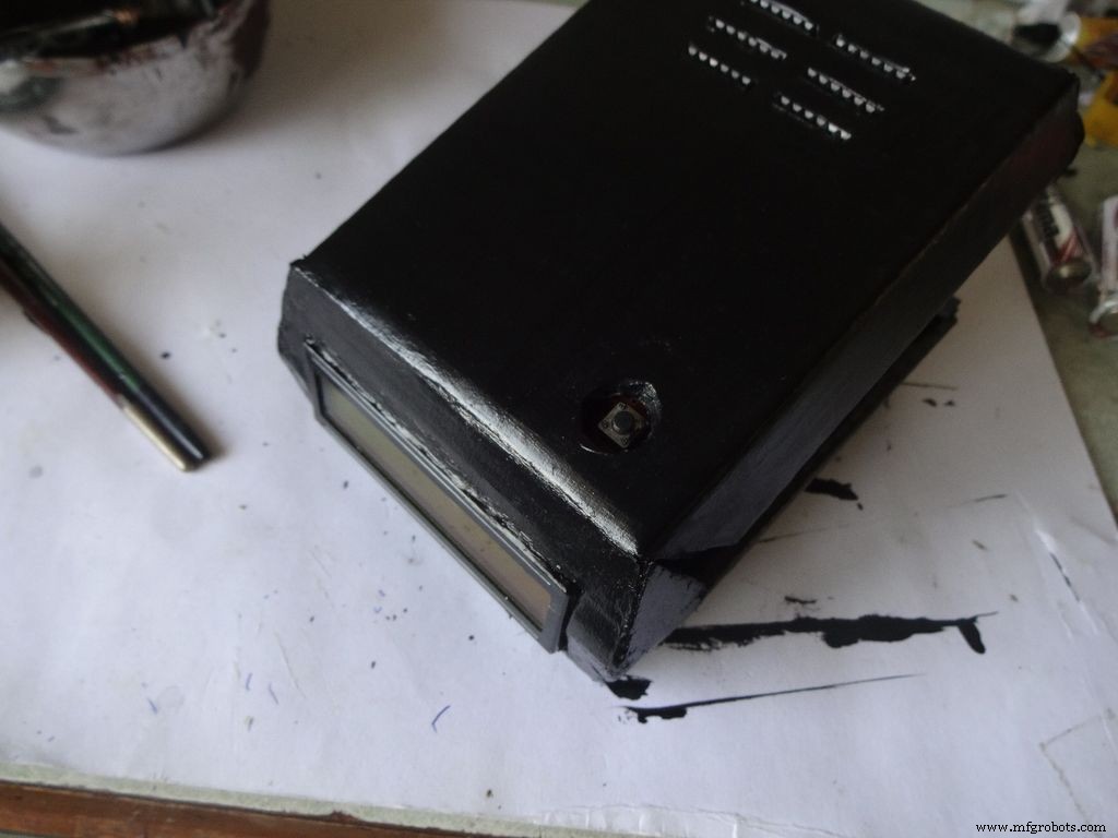
Step 21:Making the Case -- The mode button
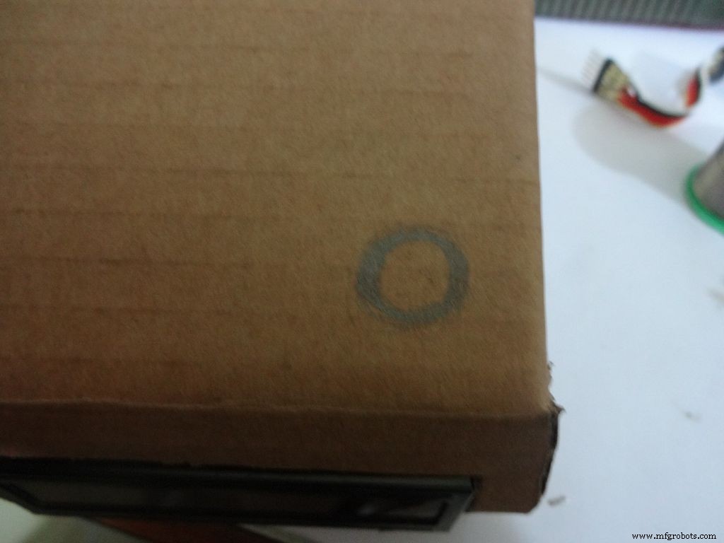
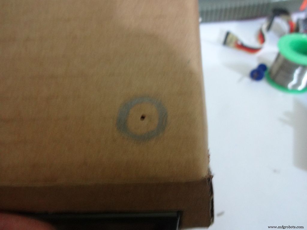
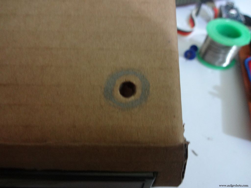
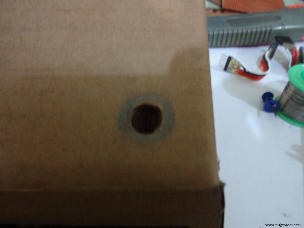
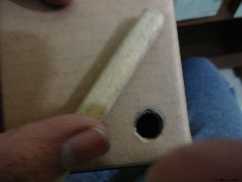
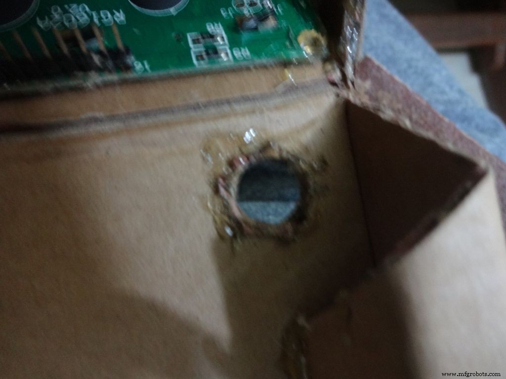


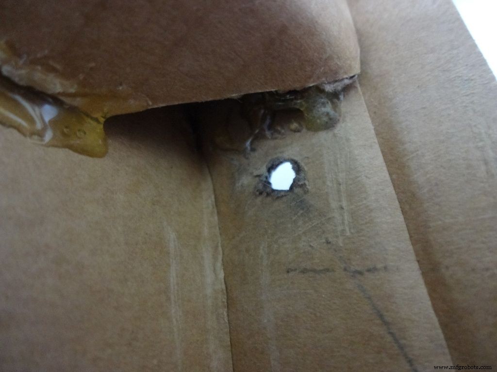
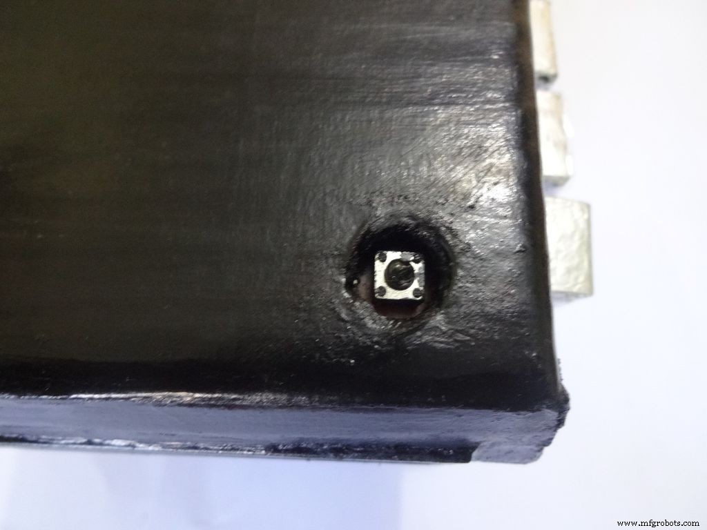
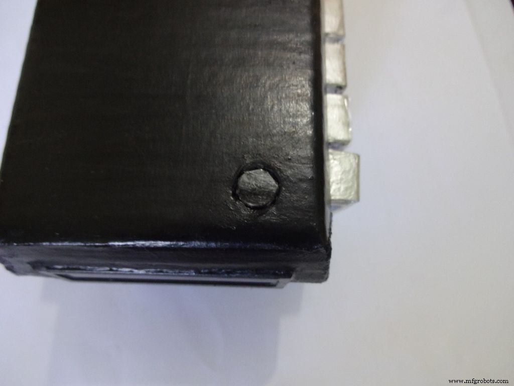
Mark a circle of about 1cm diameter at the pin1 corner of the IC case. mark the center with a pin, use a pencil to expand it. After that use some appropriate tool to increase the diameter to 1cm. Sand it on the inside and use hot glue to secure the hole.
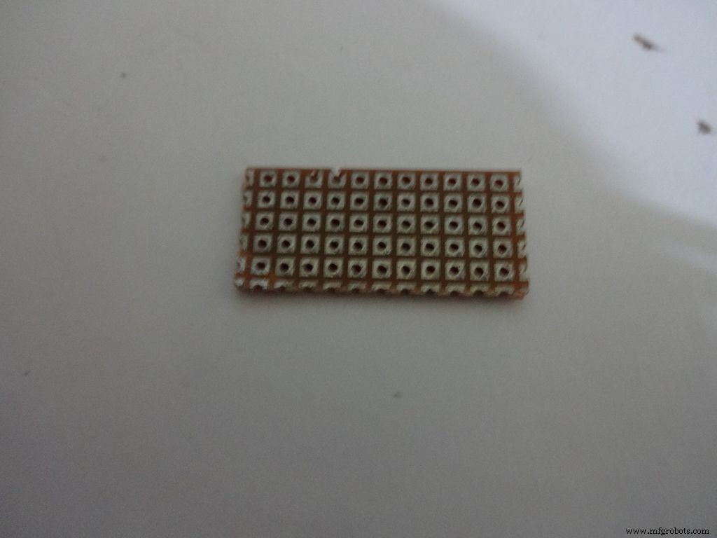
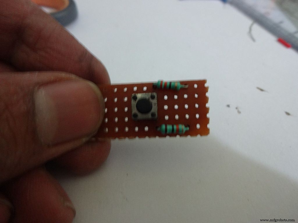
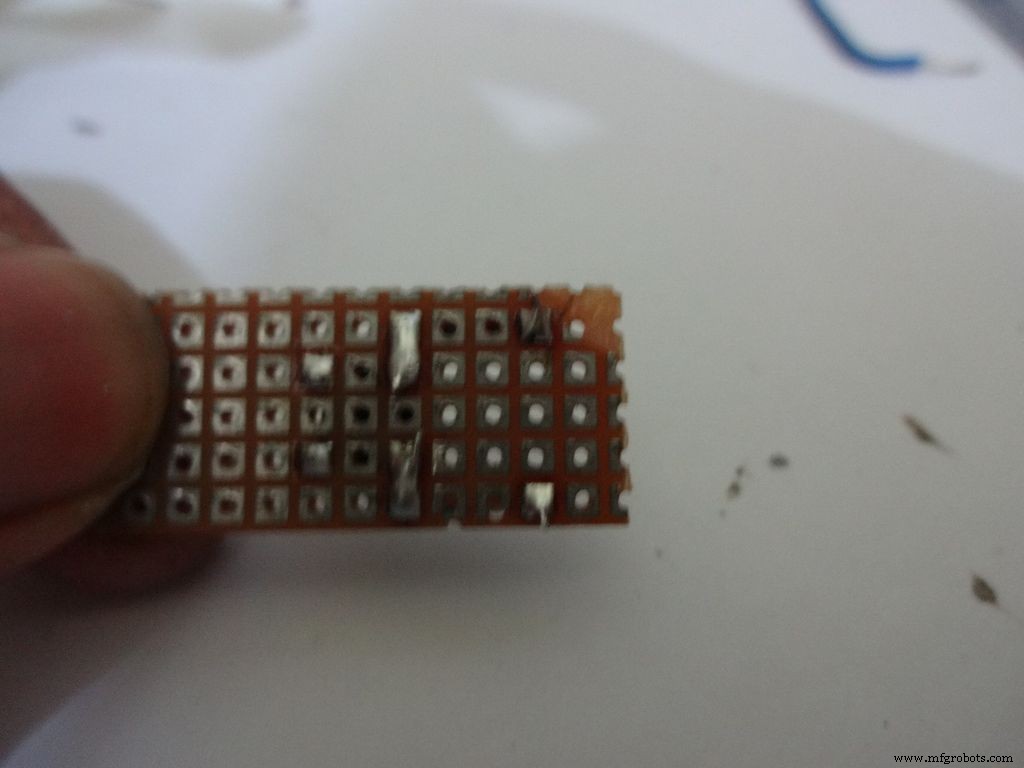
Cut a piece of General purpose PCB (10-11)dots x 5dots. Plug in and solder the pushbutton, 220 and 10k Ohm resistors as shown.
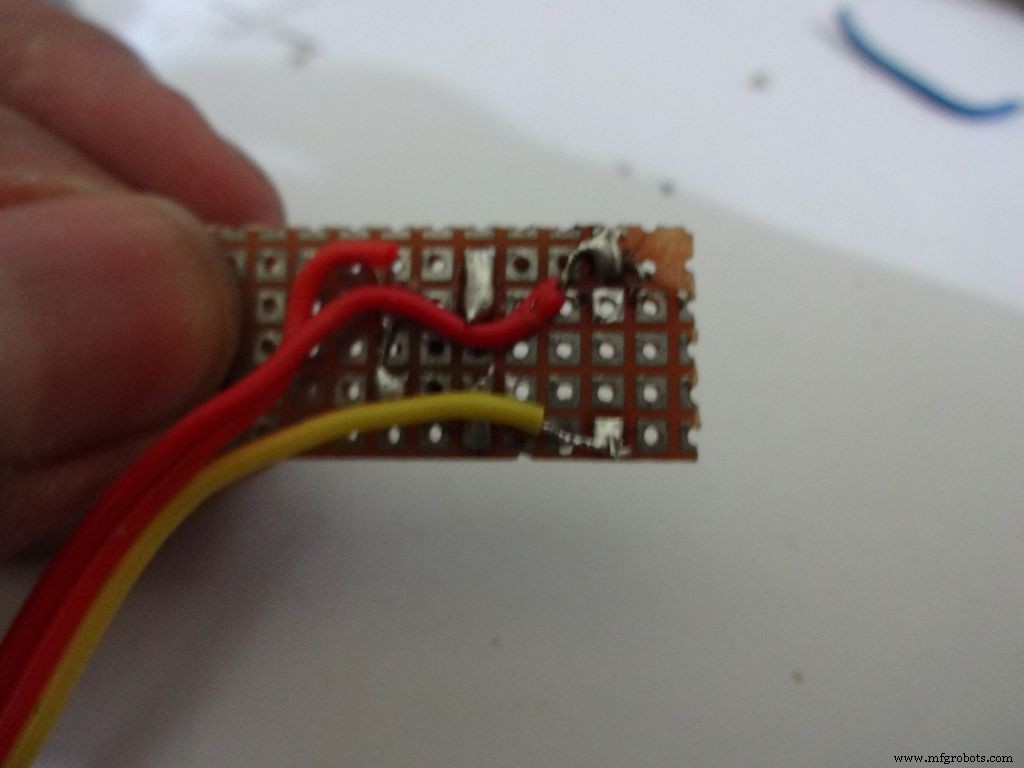
Take 3wire ribbon cable about 15cm long. Tin the ends and solder it as shown. Note down which colour wire goes to where, this will be helpful later on.
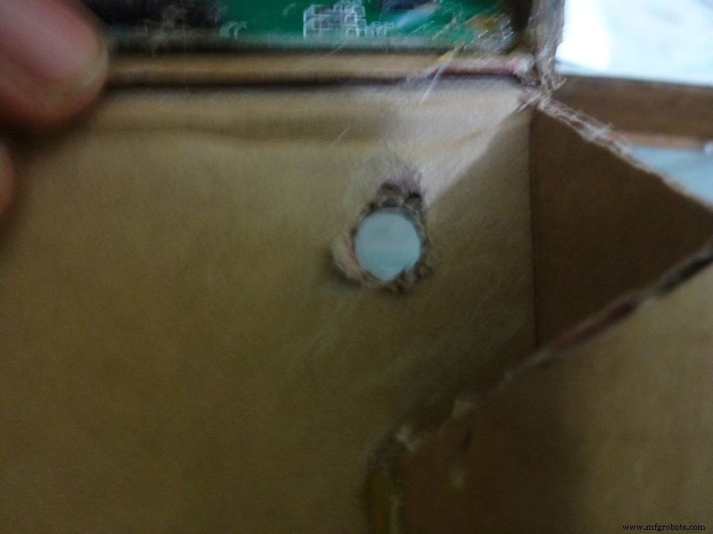
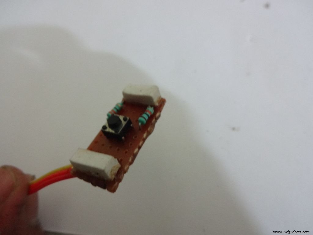
Cut 2 small pieces of eraser and place it on the ends on the board. The height of the eraser should be such that the button is below the cardboard inner level as viewed from outside. I used 4mm.
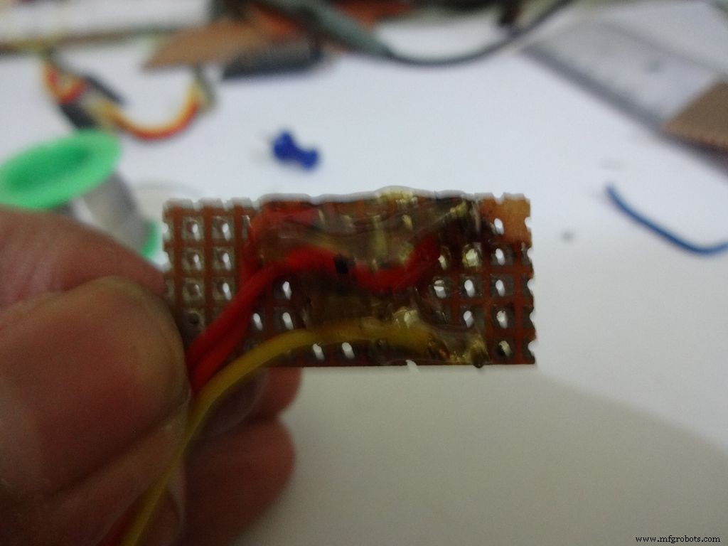
Secure it with hot glue as shown
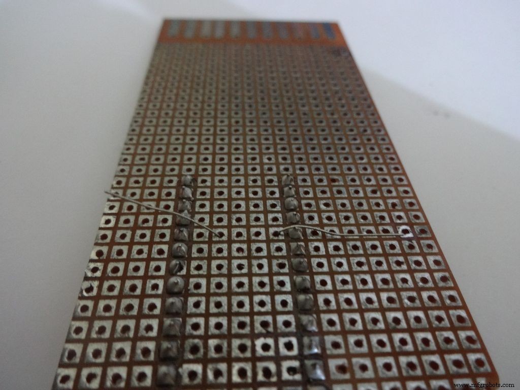
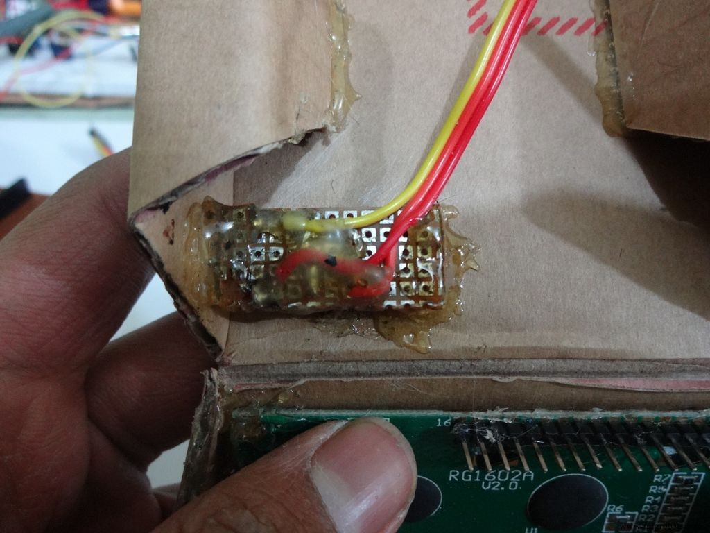
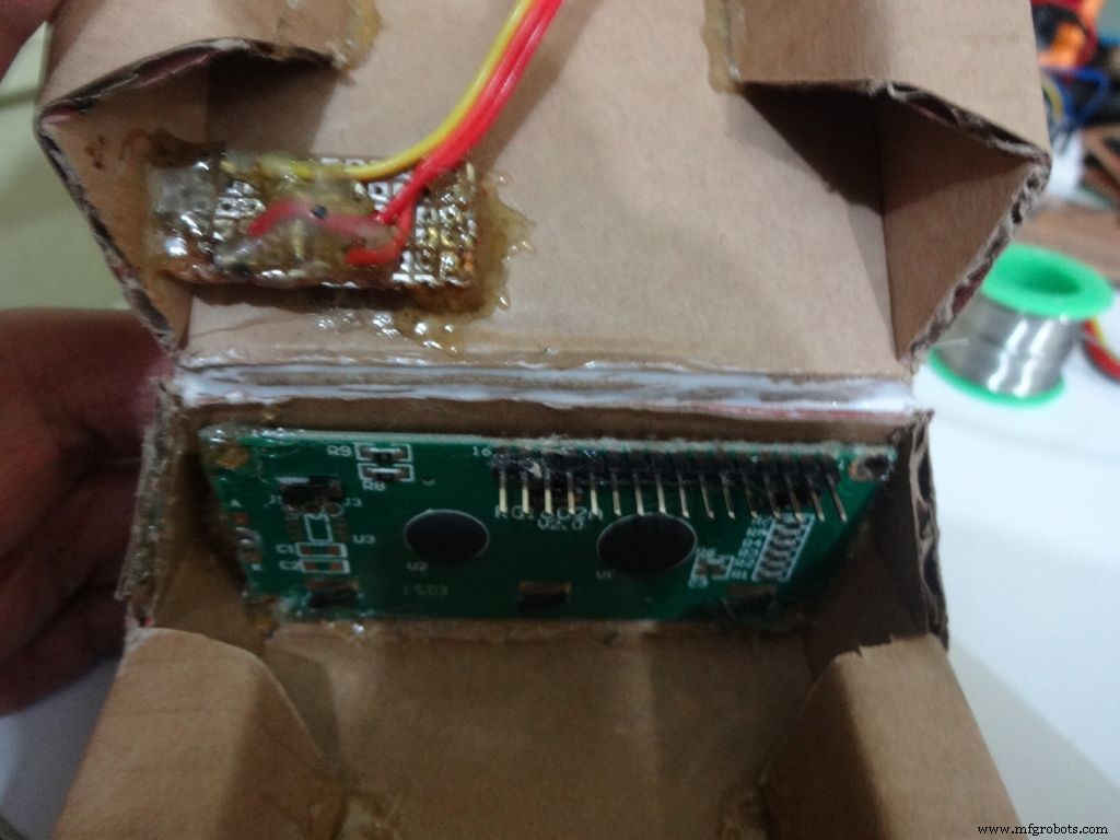
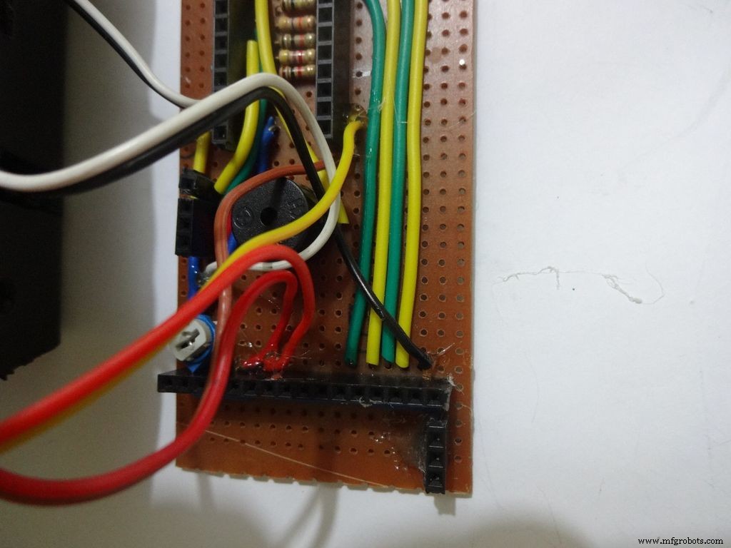
Step 22:Making the Case -- Testing points
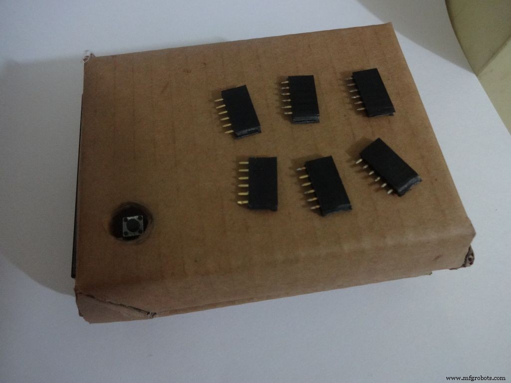
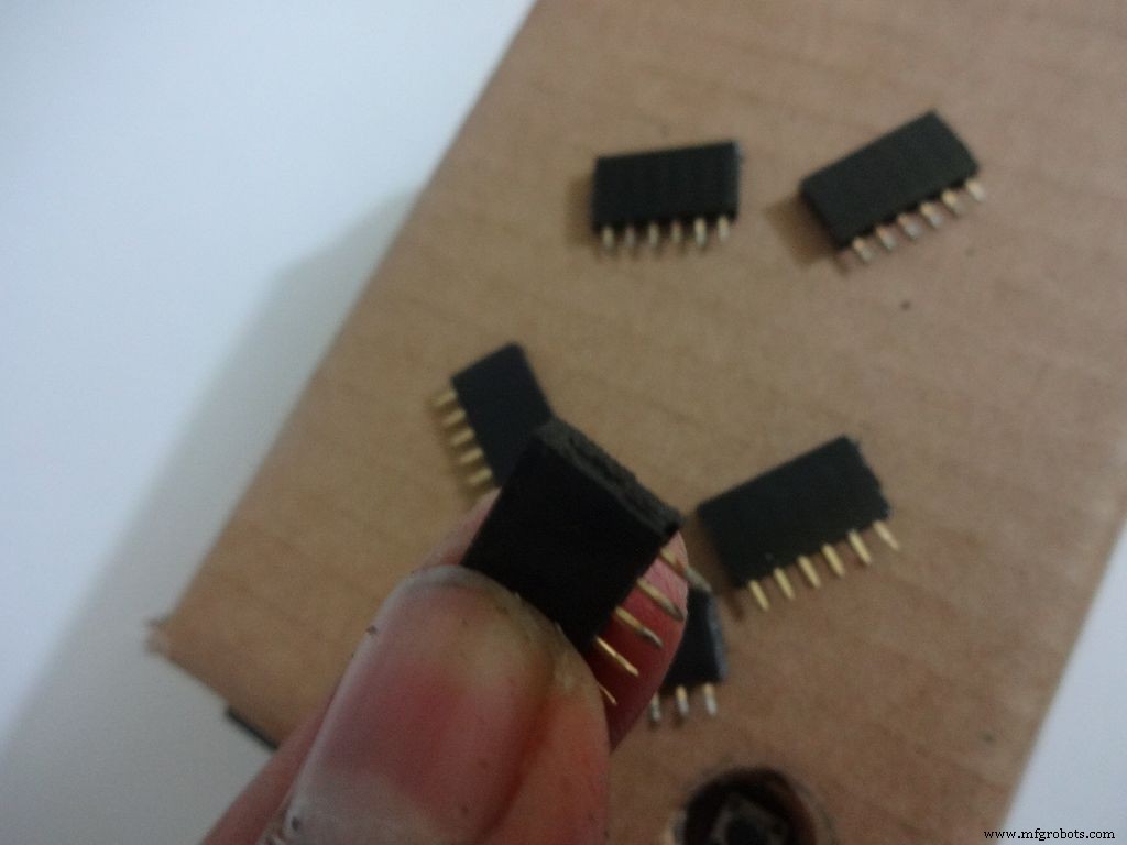
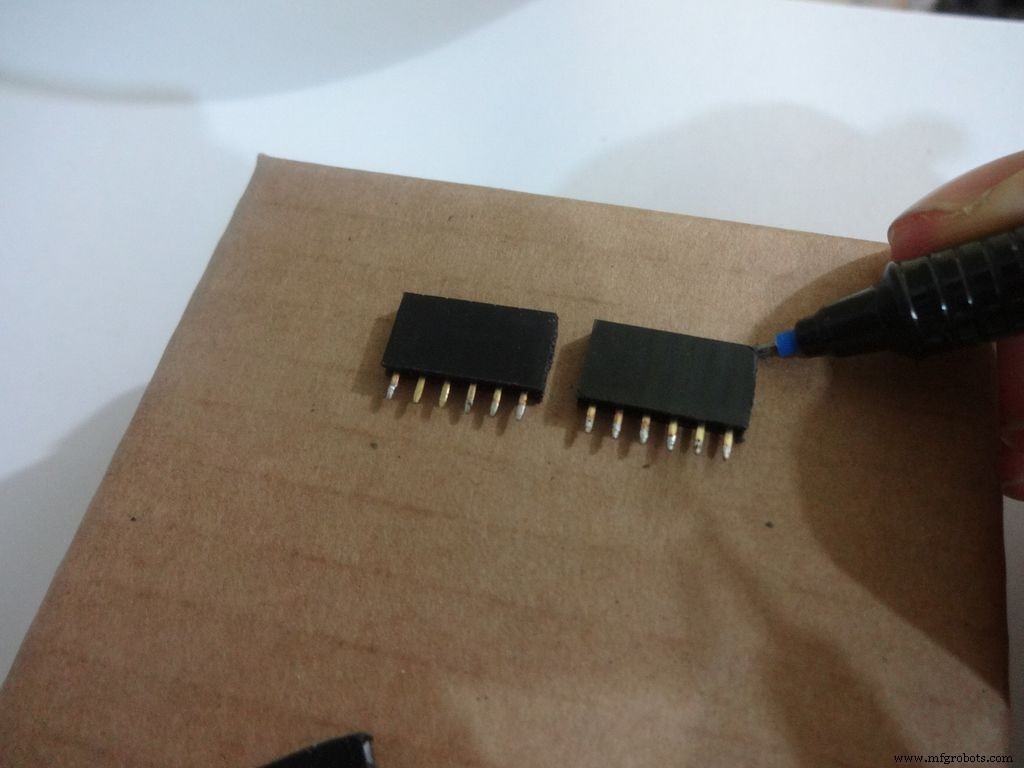
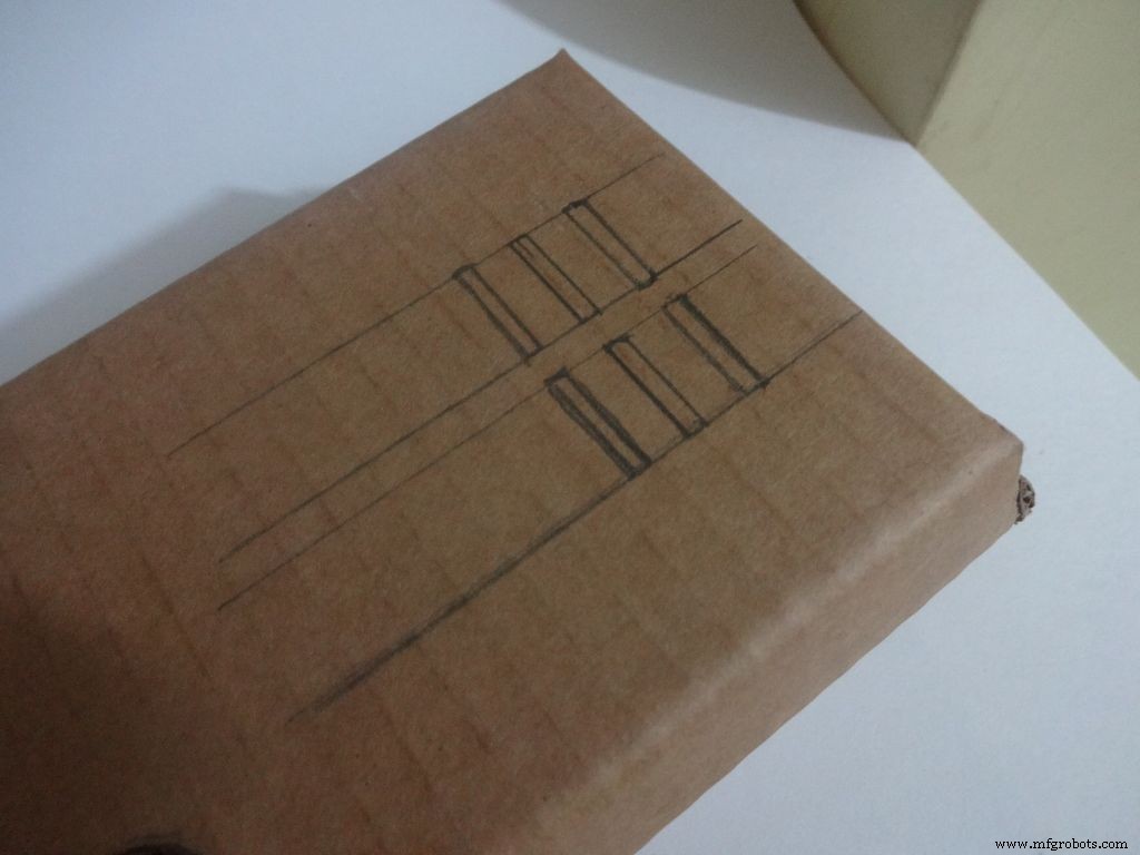
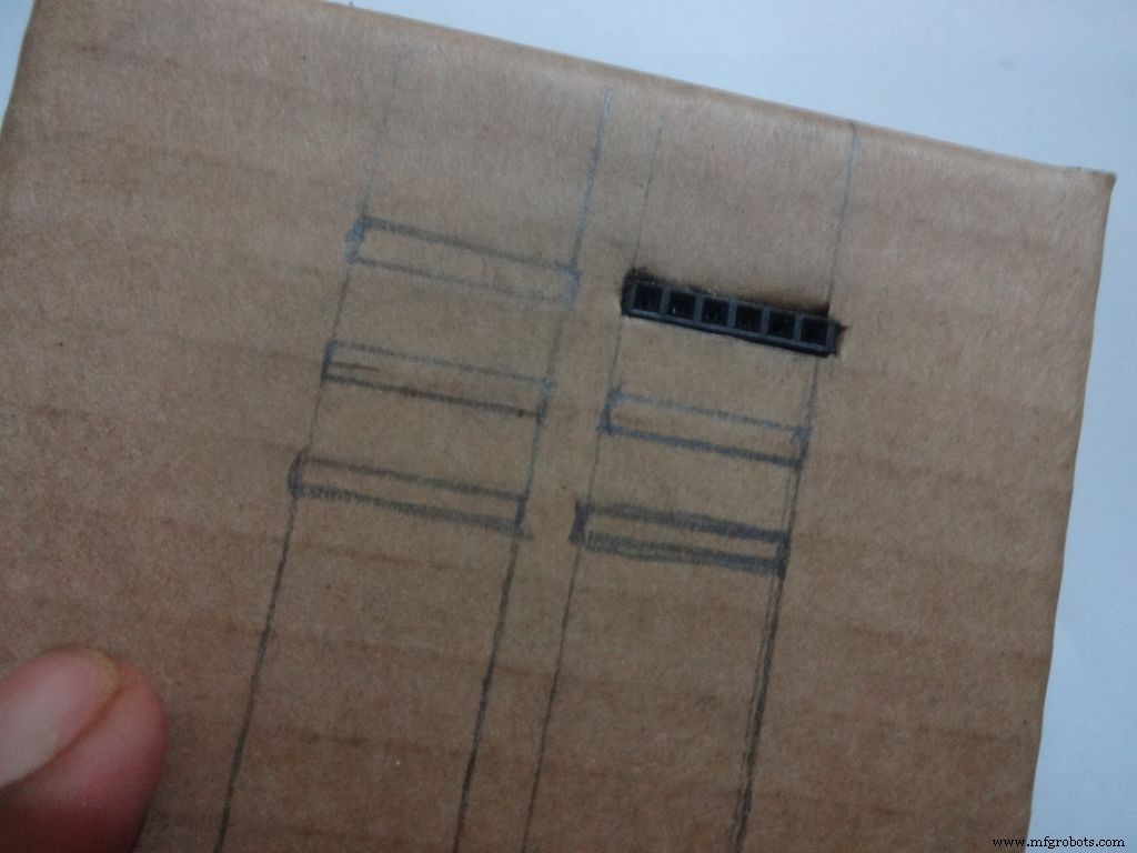
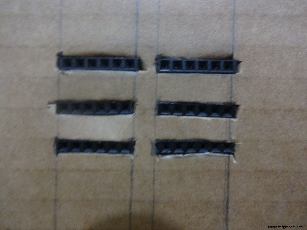
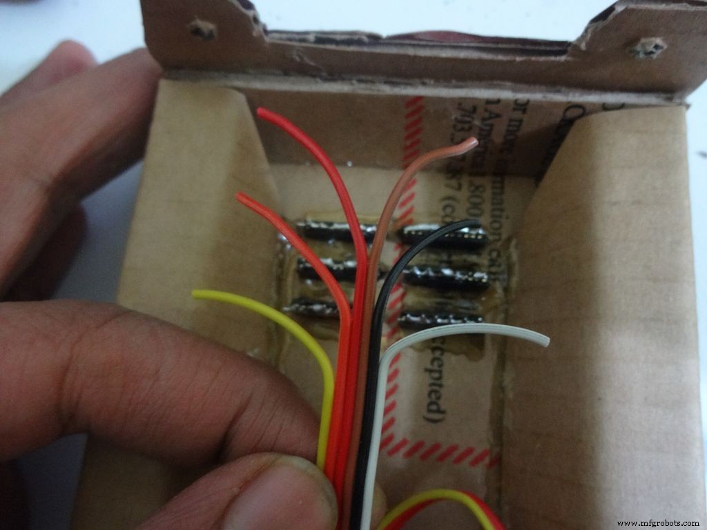
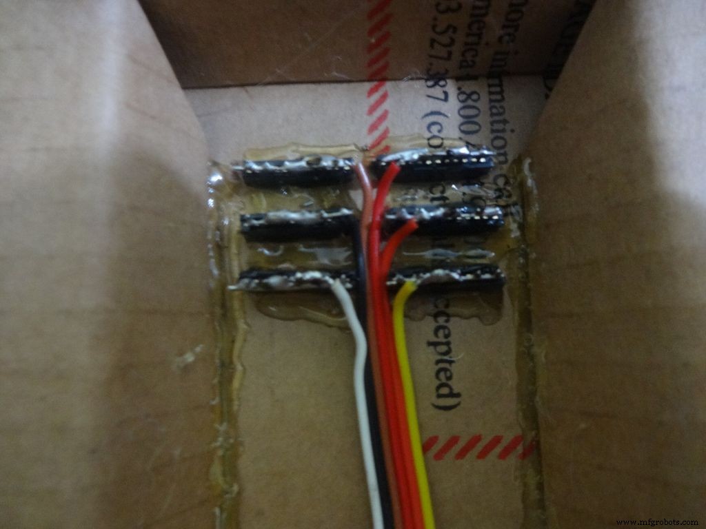
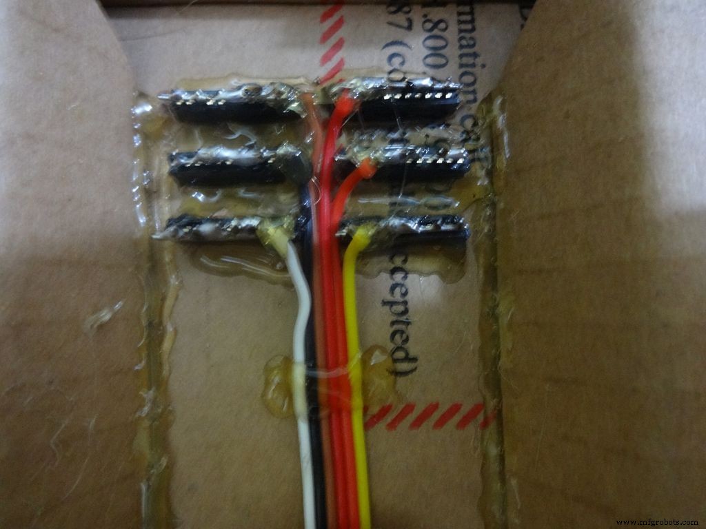
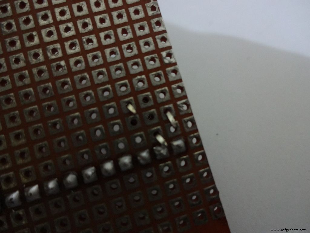
Cut 6x 6pin female header pins. Sand the sides to make it smooth.
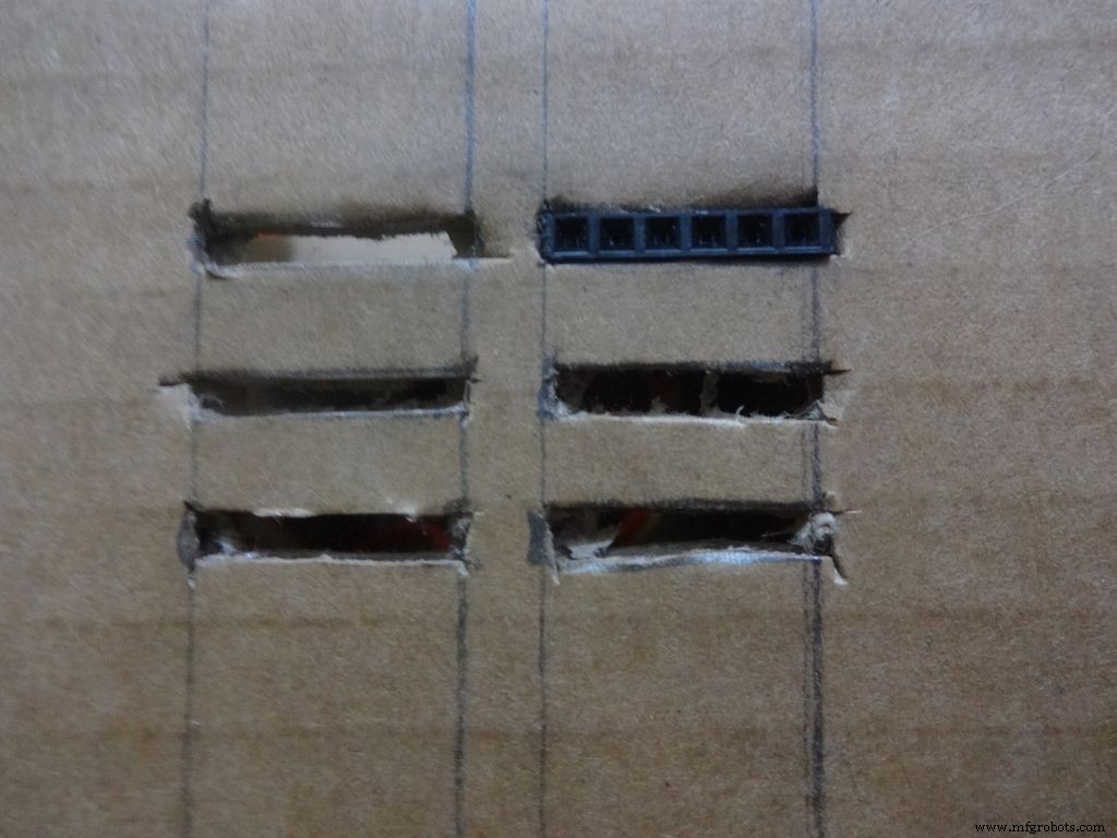
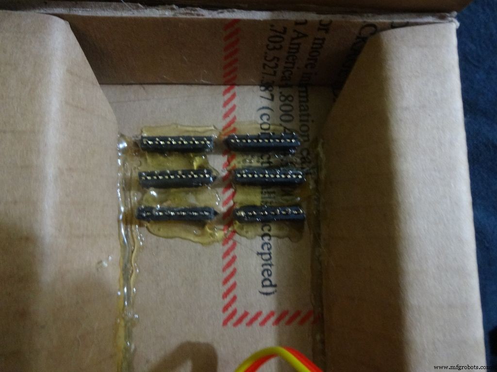
Mark the positions and cut slots for the header pins. Insert it in place and glue it from the inside.
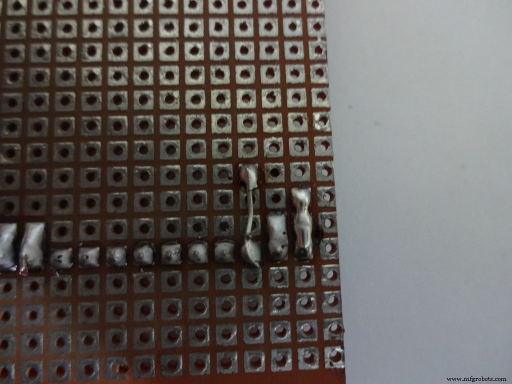
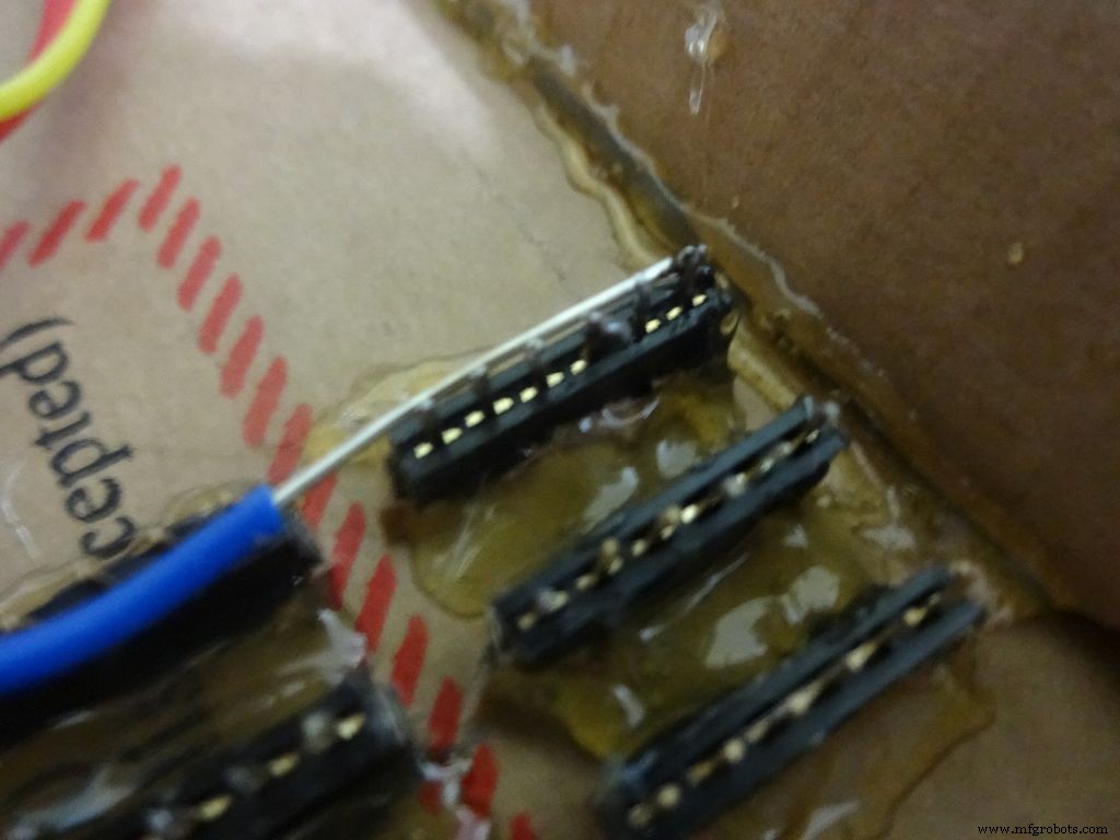
Apply small amounts of solder to all the pins and use a stripped jumper to get it all together. Make sure all of them are connected. Dont keep on heating it to make it perfect. Heating a pin also heats the neighbouring ones.
Take 6 stranded ribbon cable, tin it and attach it to each slot. Note that I put dark colours to the negative side. Apply hot glue to fix them in place.
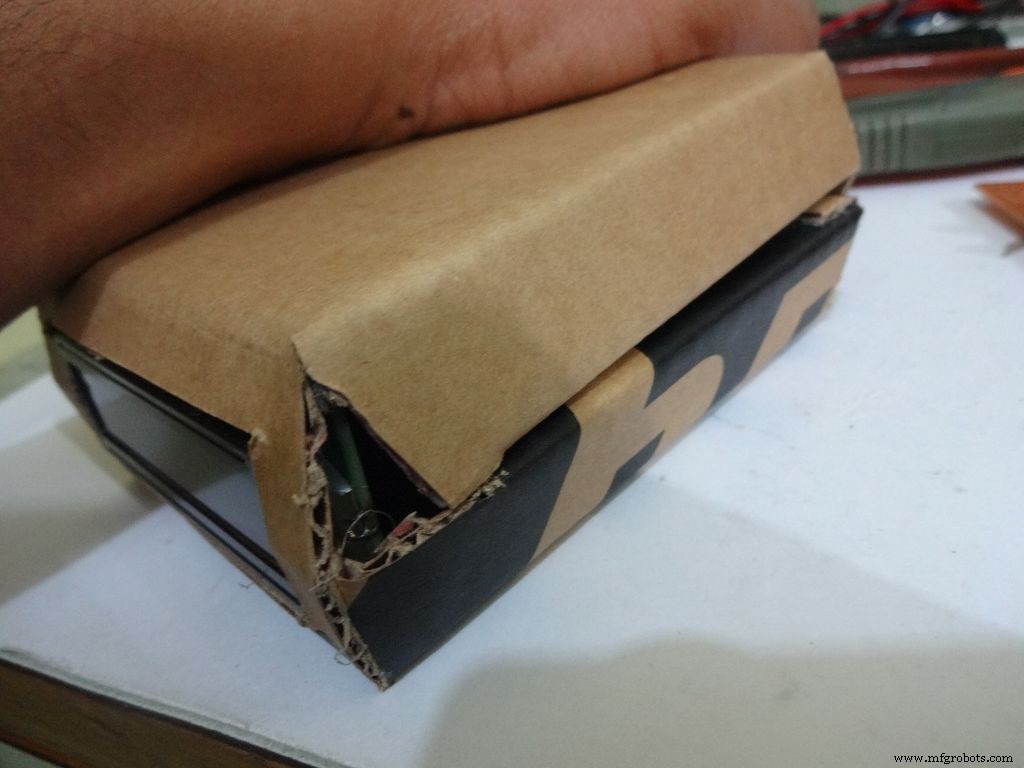
Step 23:The Legs


Download "Legs_A4.pdf" or ""Legs_ANSI_A.pdf", based of paper size available in your region. attached at the end.
Print it on an A4 size paper (21 x 29.7cm or 8.27 x 11.69 inches) or the US-alternative ANSI A(8.5 x 11inches or 21.6 × 27.9cm). Make sure that while printing you select the proper paper size, orientation, and select the "Actual Size" option. Confirm that the print is accurate by measuring the rectangle. It should be 8.4 x 11.8cm
Cut crease and glue it just like the main case, see the images.
Step 24:Making it shiny!
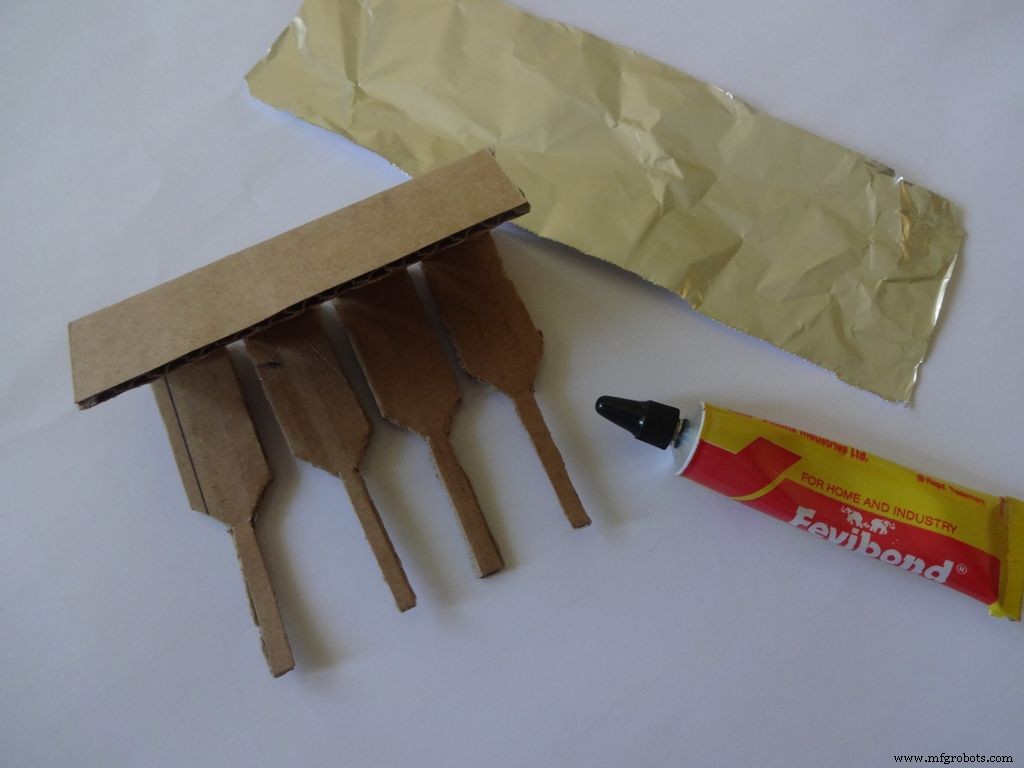
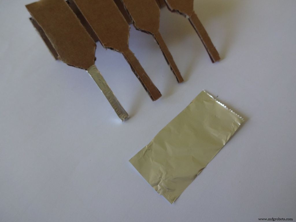
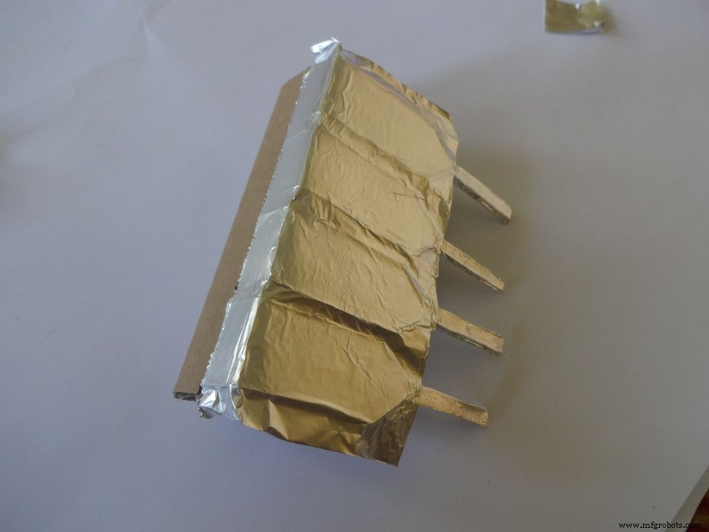
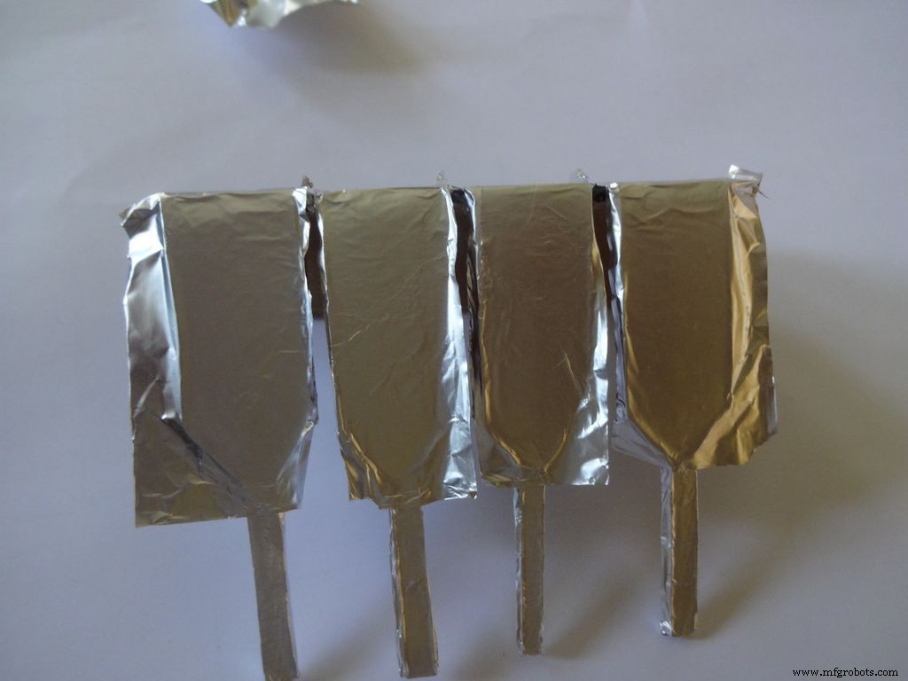
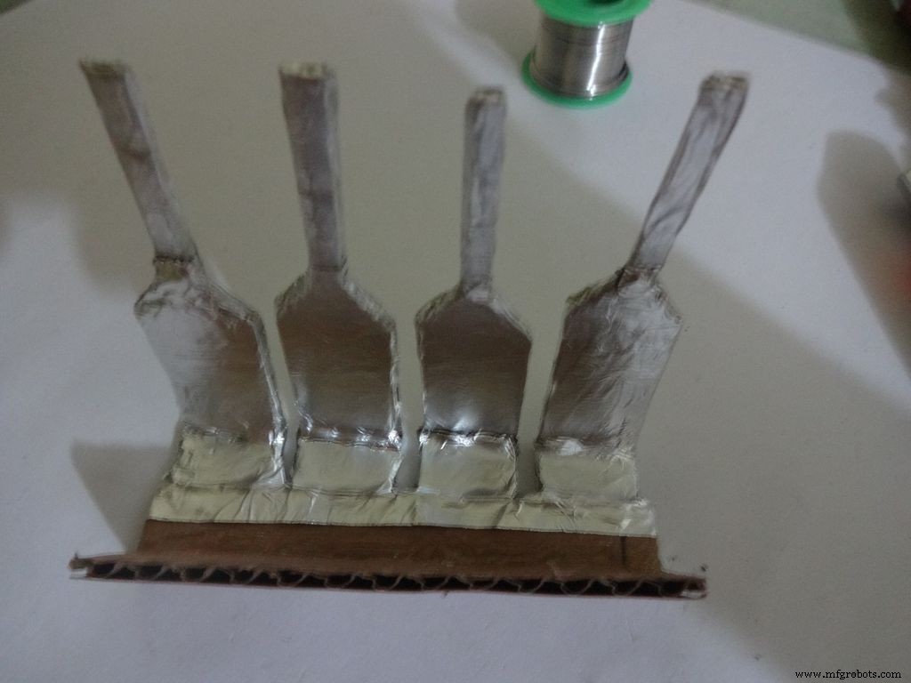
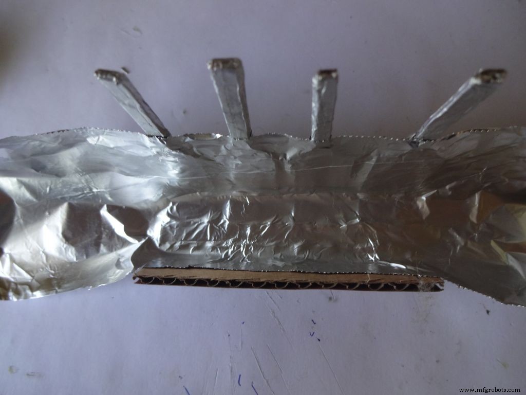
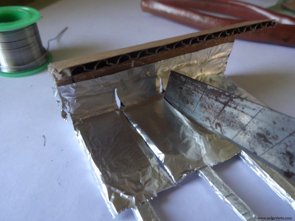
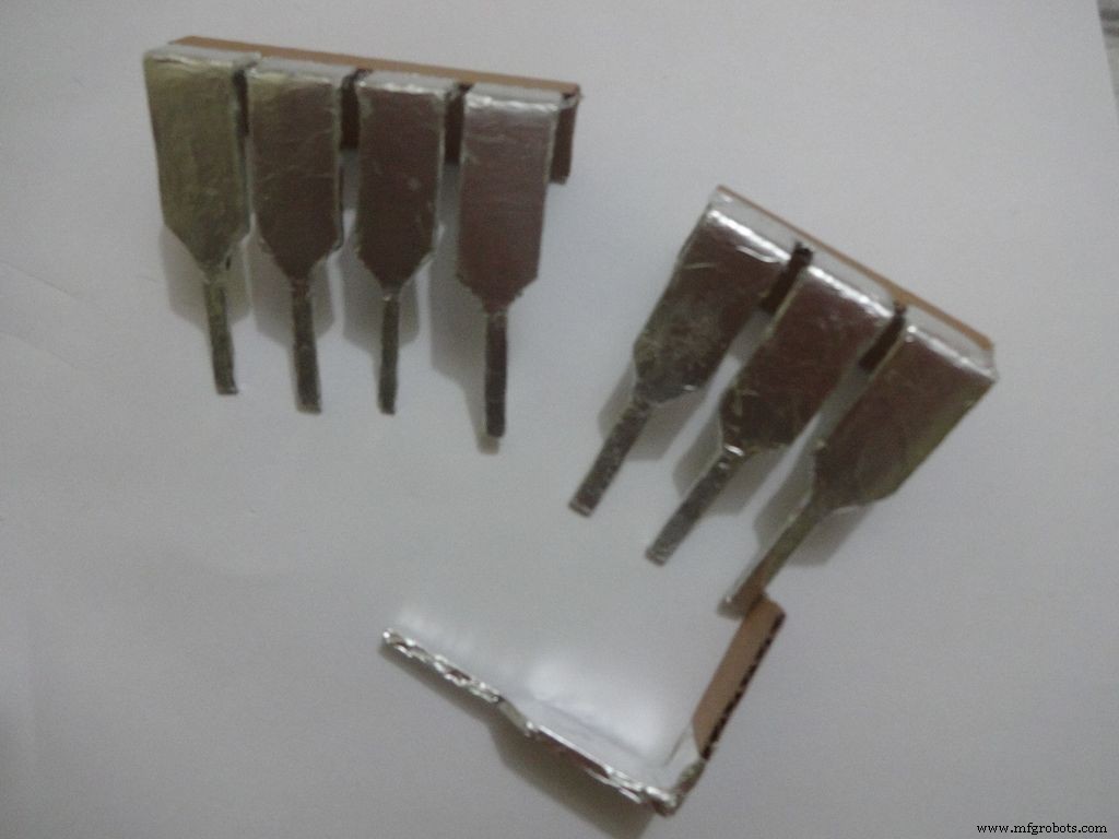

Cut a piece of foil 1x2inches and stick it carefully, fold by fold to the leg ends with some metal-cardboard sticking glue. I used Fevibond.
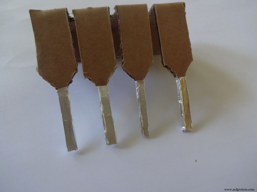
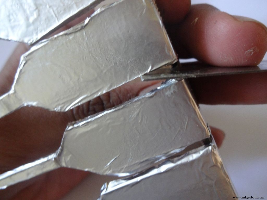
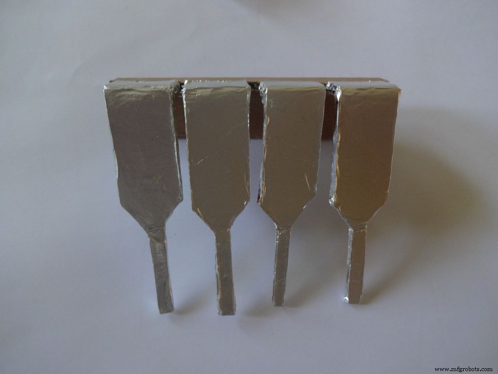
Next stick a patch that covers all the leg tops(as shown), make cuts slowly with a cutter. Do this carefully. The foil tends to tear to the sides. Use something flat to stick the foil in between the legs and give it a good finish.
Now cover it with transparent cello tape, just like you applied the foil, to protect it from sharp objects.
Step 25:The Power Switch
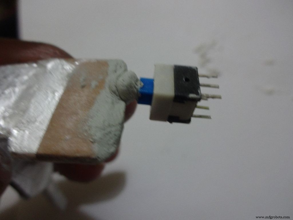
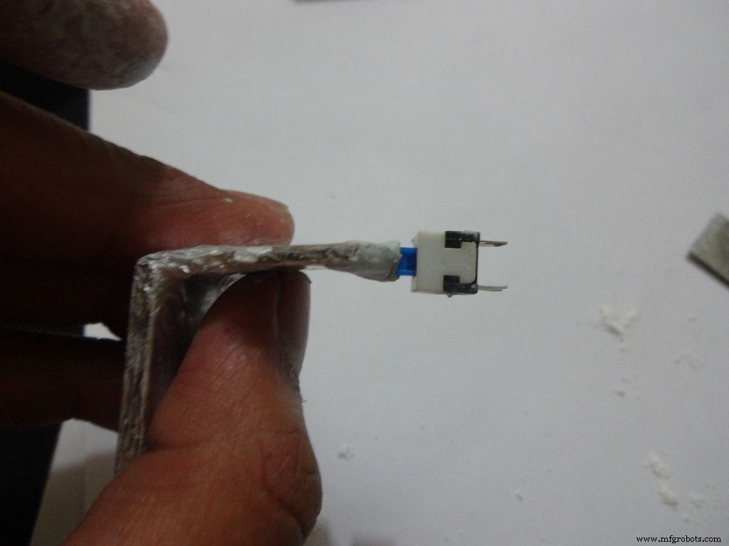
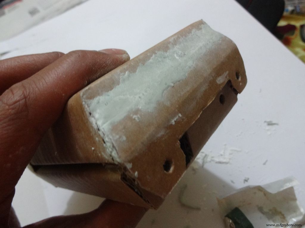
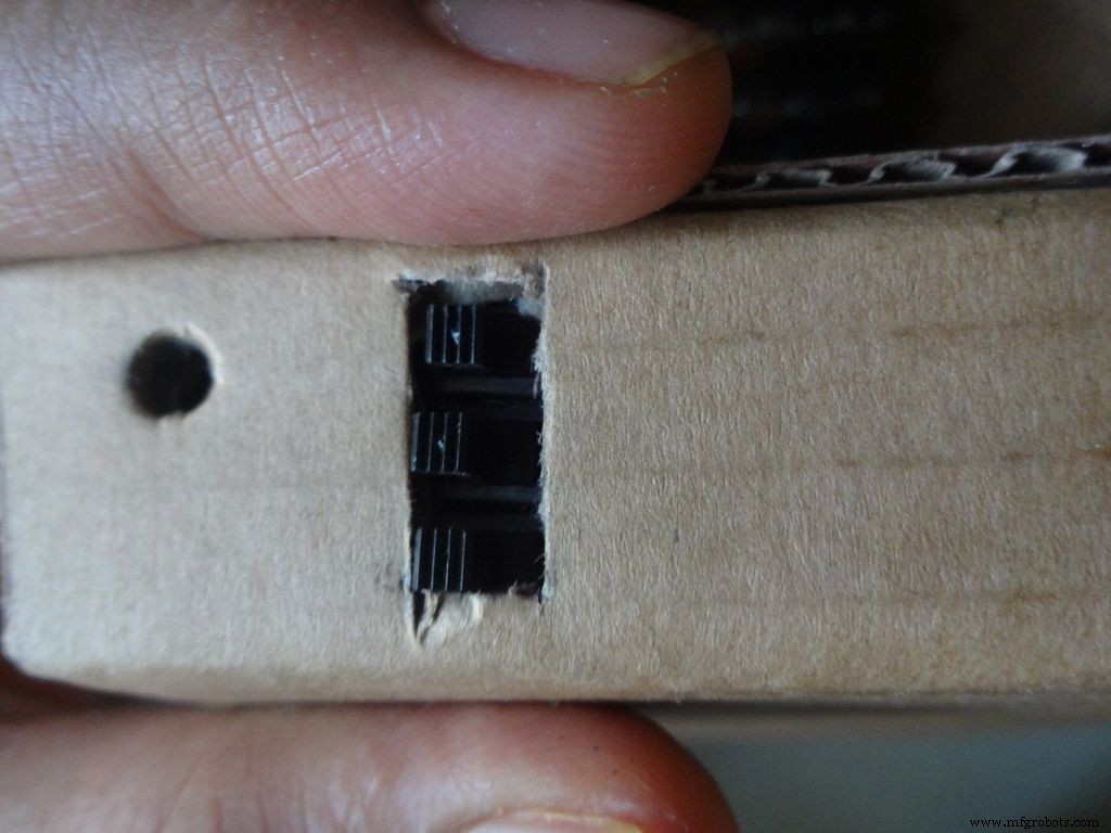
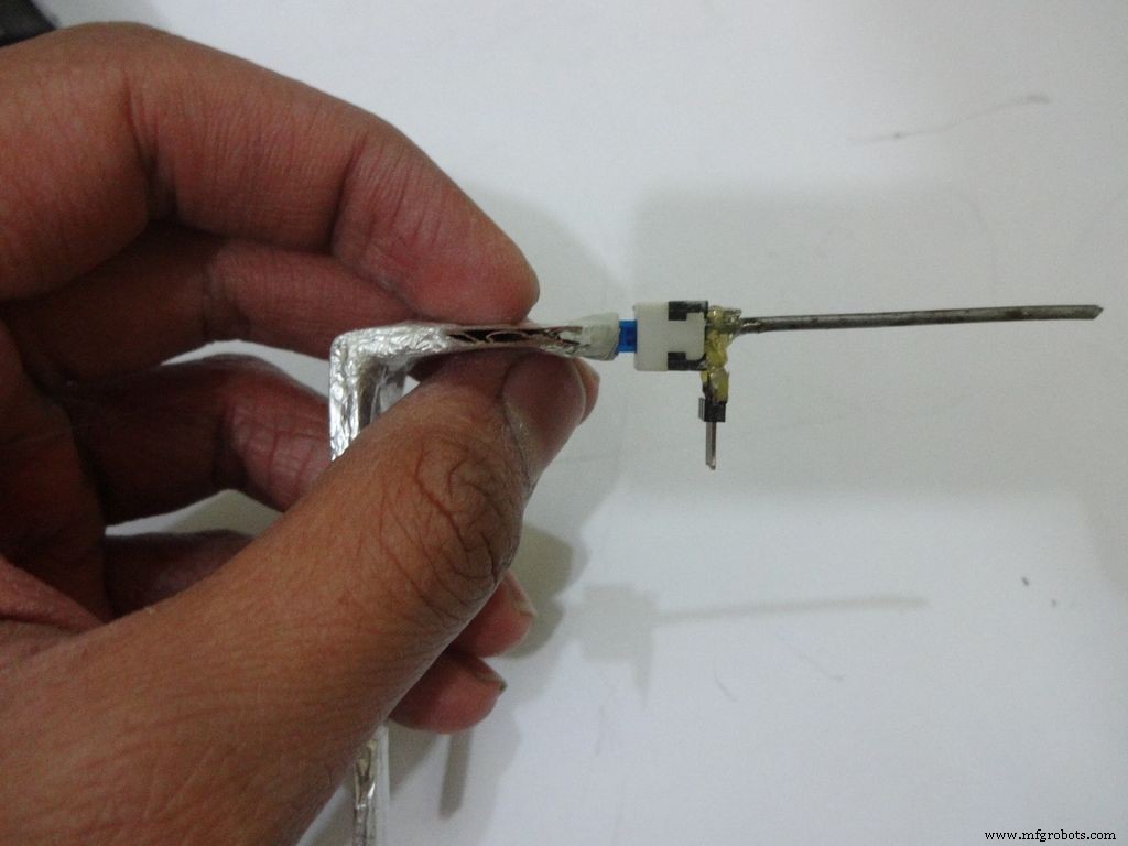
Measure and cut the power switch leg by properly keeping it in place. Temporarily stick the other pins with tape to get the pin1 position right.
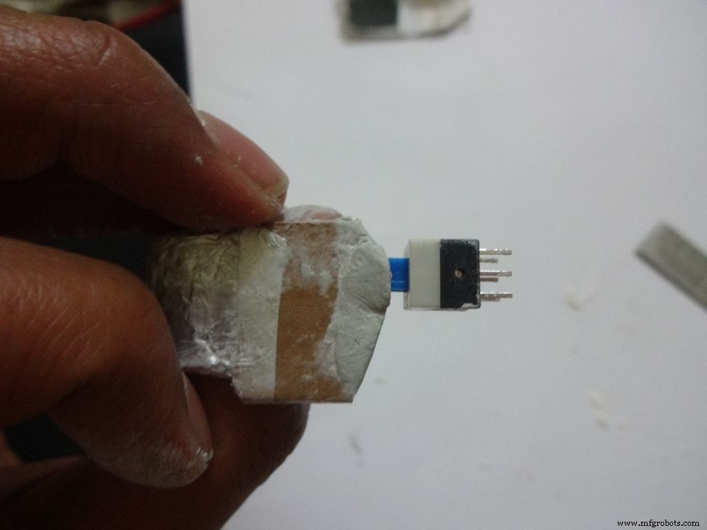
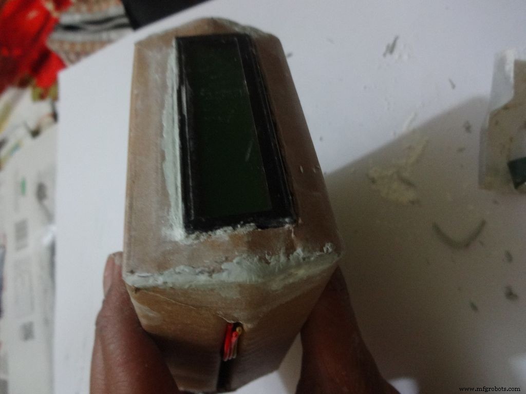
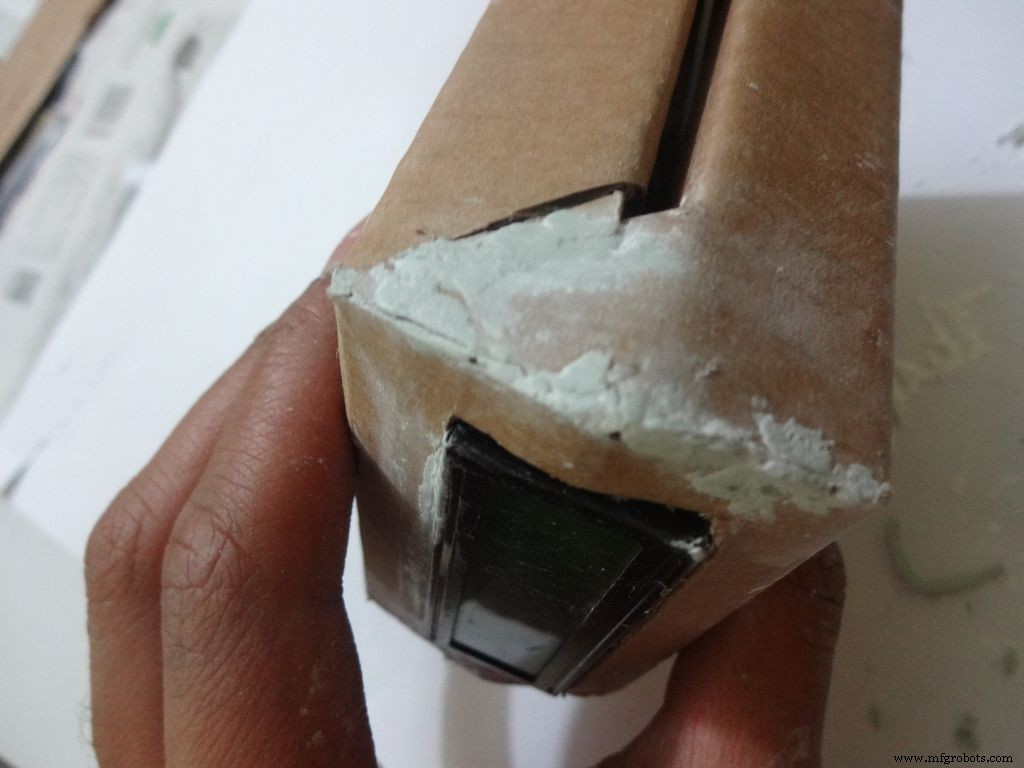
Mix the m-seal(epoxy putty sealant, gets very hard when it dries) well. Put it as shown in the images and use powder+flat surface to shape it. Let it dry.
Also fill any gaps left in your case.
Note:We cant use hot glue here as it is rubbery and the switch needs to be stuck with some strong brittle material.
Step 26:Power switch to PCB
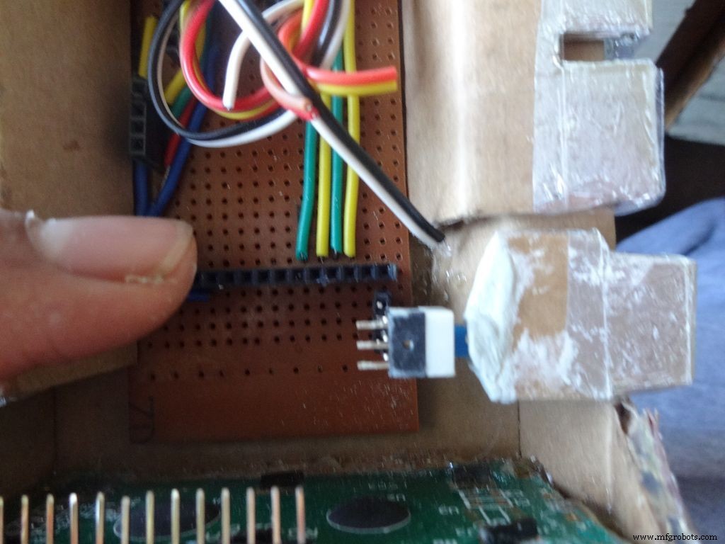
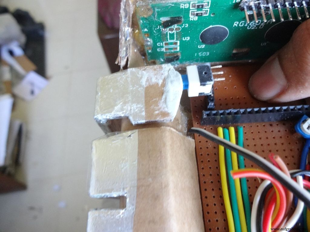

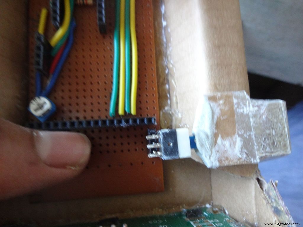
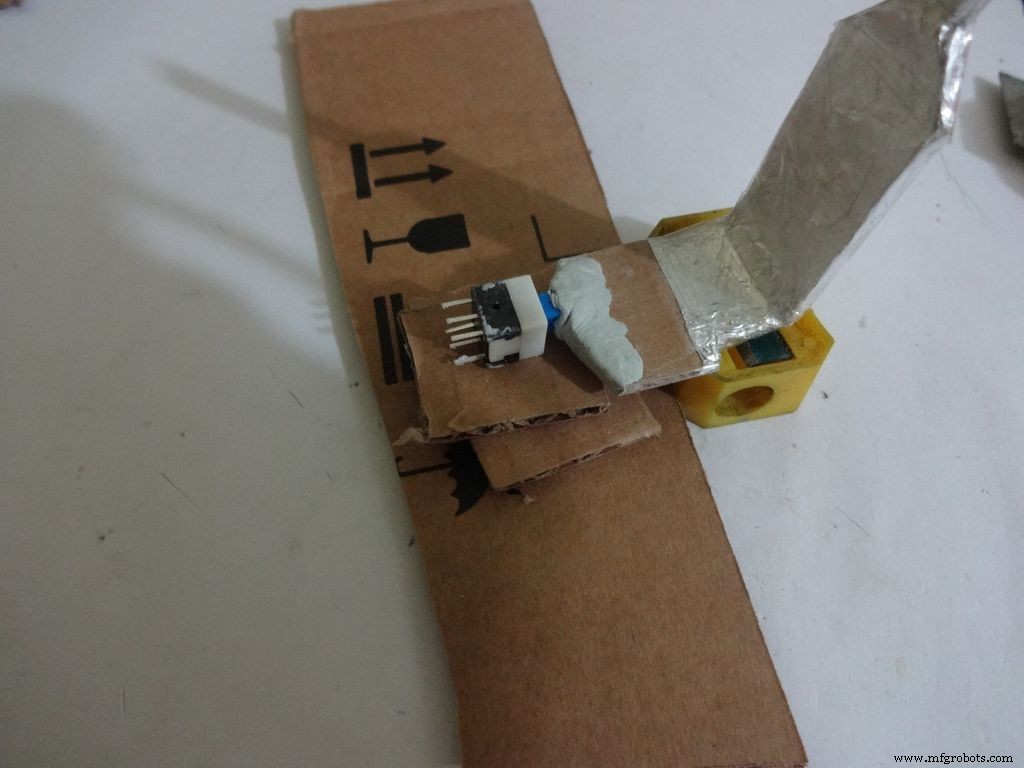
After The m-seal dries, place it in to check if everythings alright.
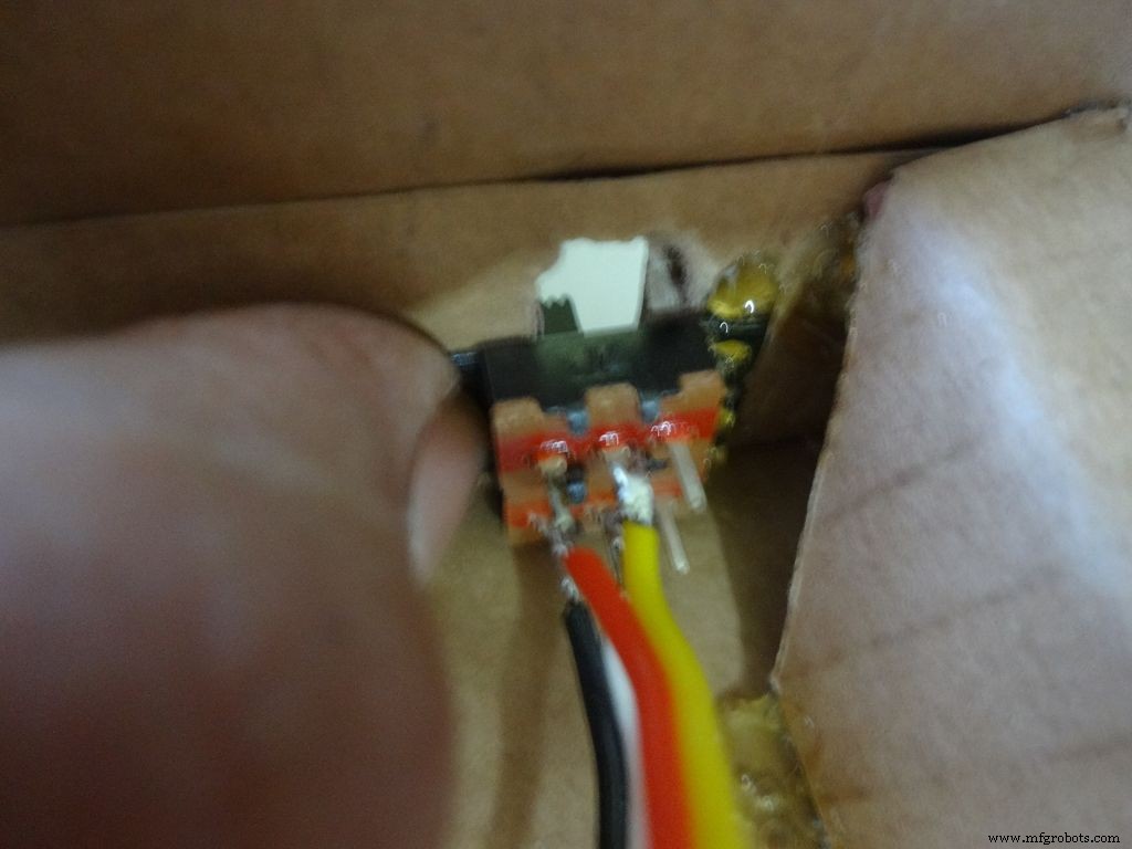
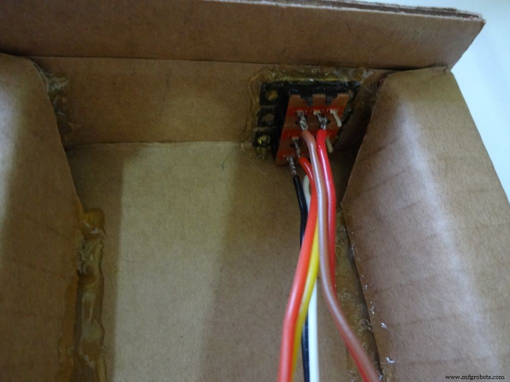
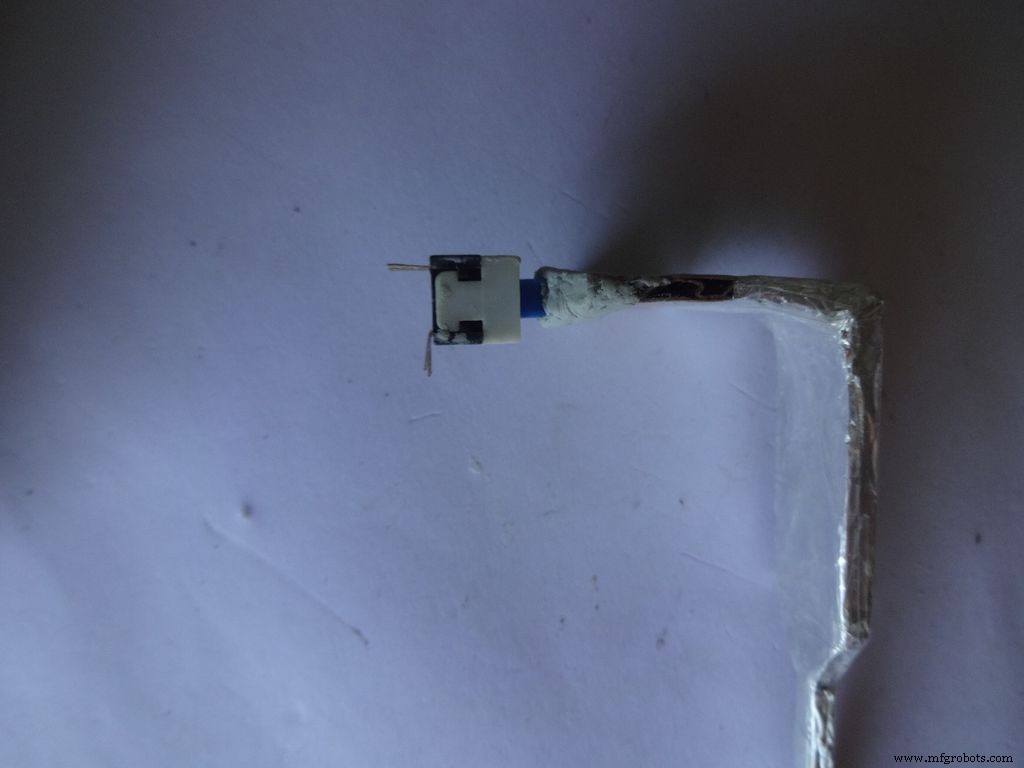
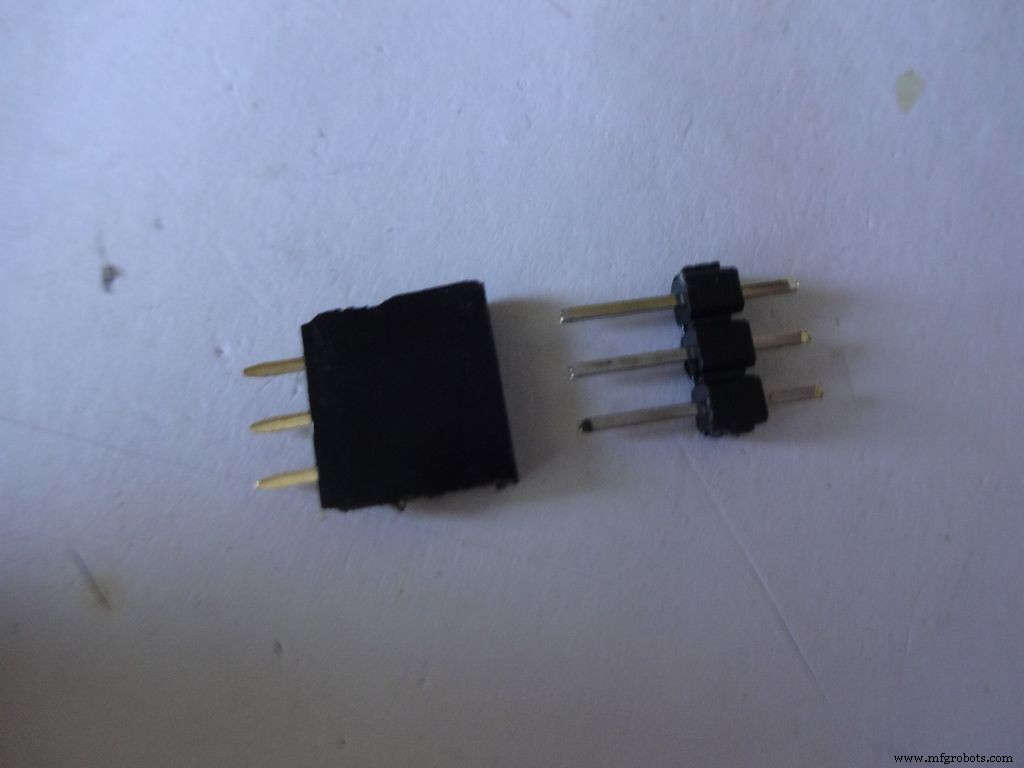
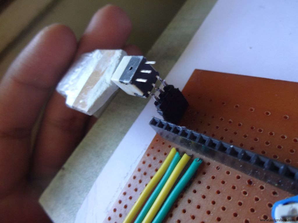
Cut 3pins of female and male headers place it on the PCB such that it aligns with the switch pins. Solder the female part.
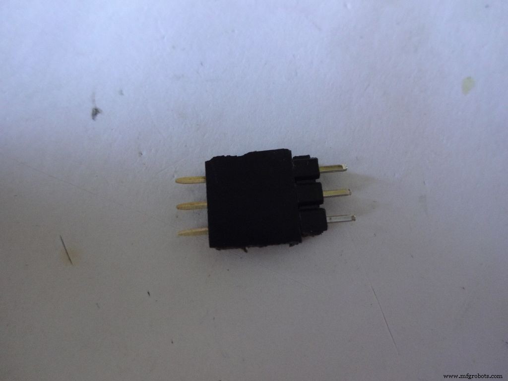
Tin the switch leads and the male header pins, join them. See if it fits at the right place.
Try pushing the switch on and off after placing a finger behind the switch for support. We will add a support rod later on.
Connect a side pin of female header(power switch) to Vin. I realised this late and had to undergo lots of trouble.
Secure the header Pin with hot glue.
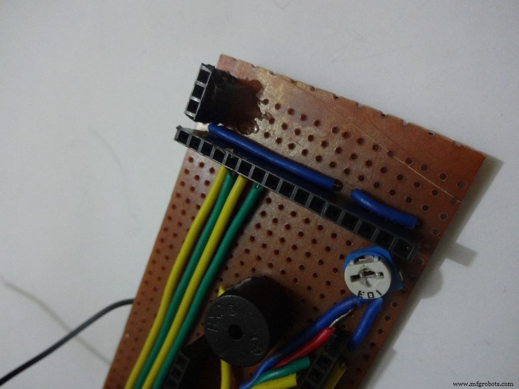
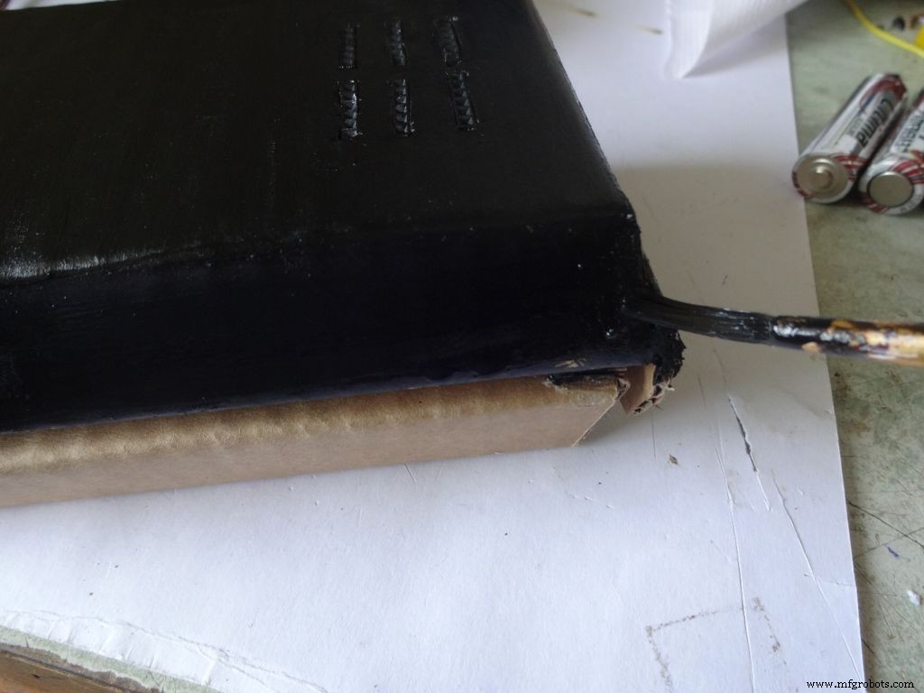
Step 27:Making the USB Port

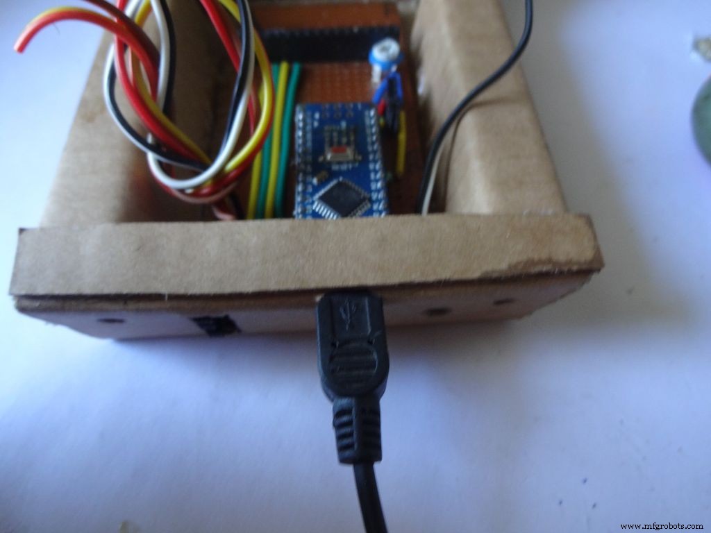
Put the PCB properly in (with Arduino) and cut a rectangle for the mini USB port.
Remove some plastic from the USB cable so that it fits the Arduino properly. Test whether connection is proper.
Step 28:Some other things...

I removed all the LEDs from the Arduino Nano and also the power LED on my RTC module. These consume unnecessary power, which matters if you are operating on a battery.
Sand the dried m-seal so that it mixes smoothly with the cardboard. Clean the powder with a wet paper napkin before painting.
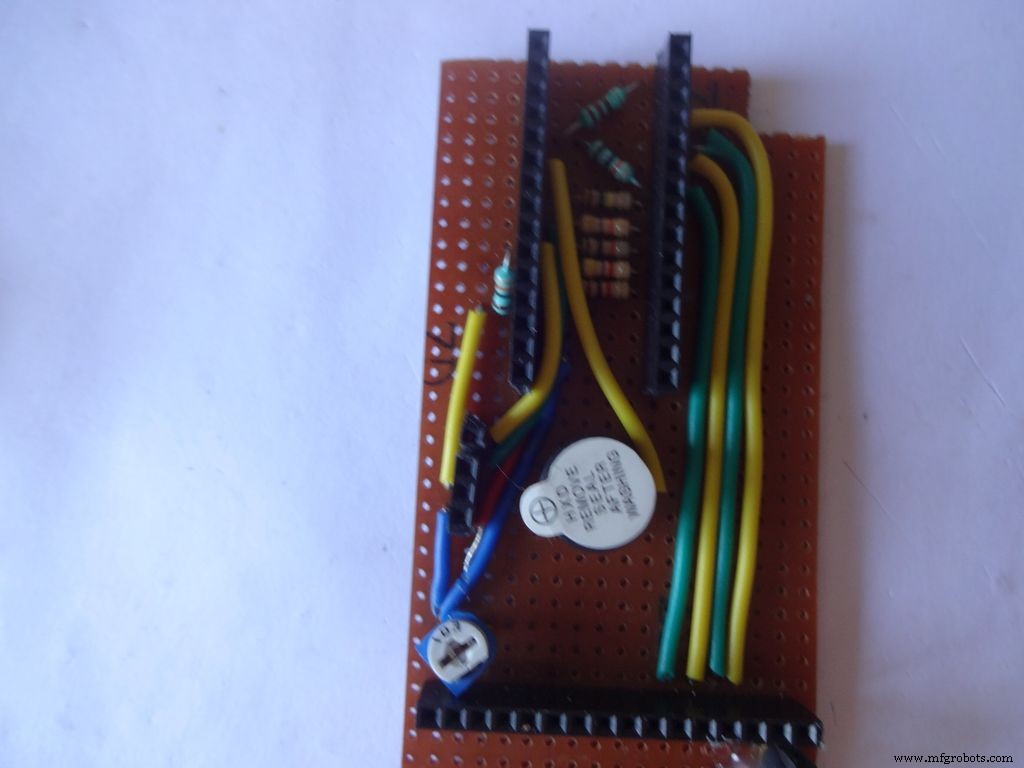
I also added a buzzer which may be used for some functions. Buzzers are sensitive, don't use too much heat while soldering!
Step 29:Time to paint!
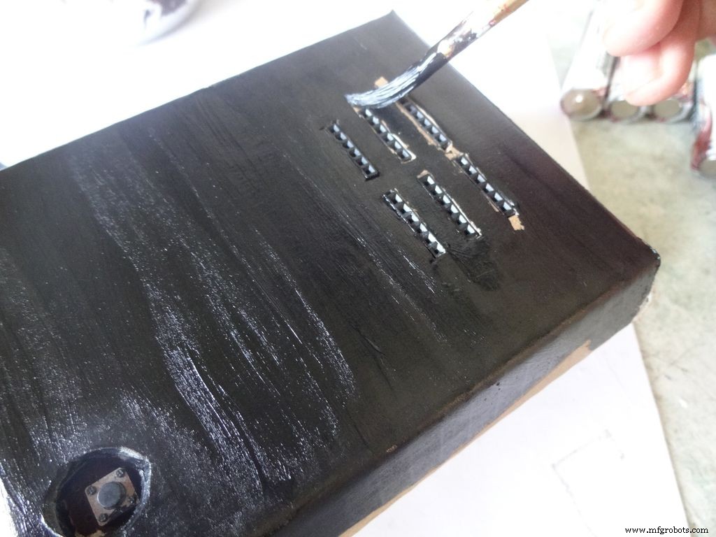
Dont use direct thick paint while painting, this cases brush patterns to appear. Use sufficient water.
Make sure no tiny bubbles are formed. These form when you dab the brush too much.
Dont paint the cover hinge, the paint will restrict it.
This is just a base coat. Another layer of paint will be added while finishing up.
Step 30:Soldering all the wires
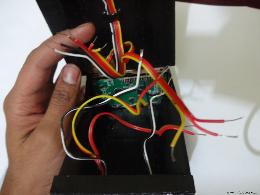
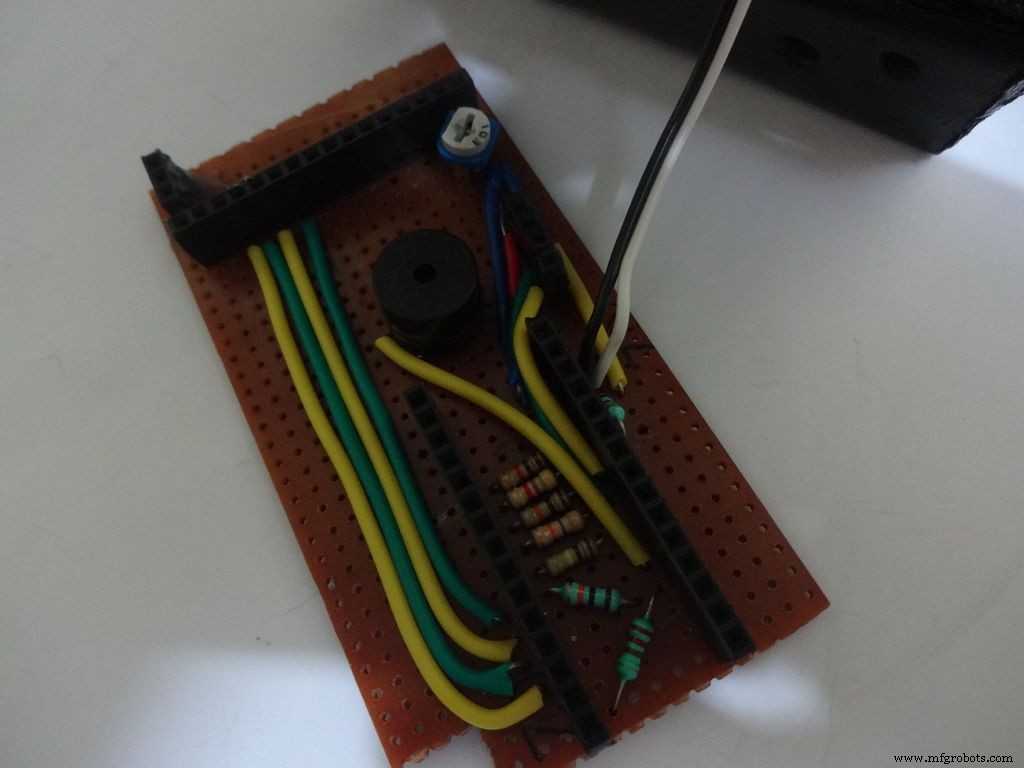
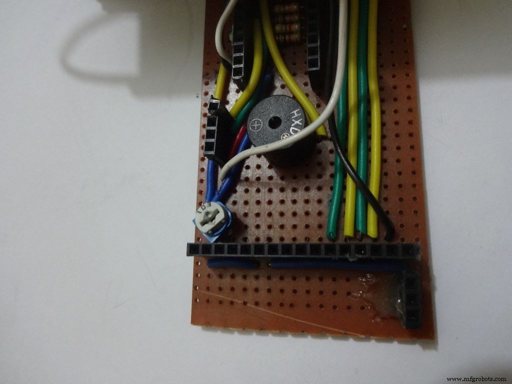
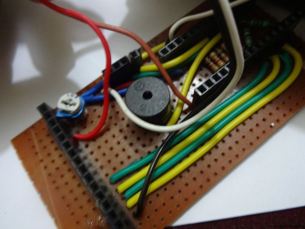
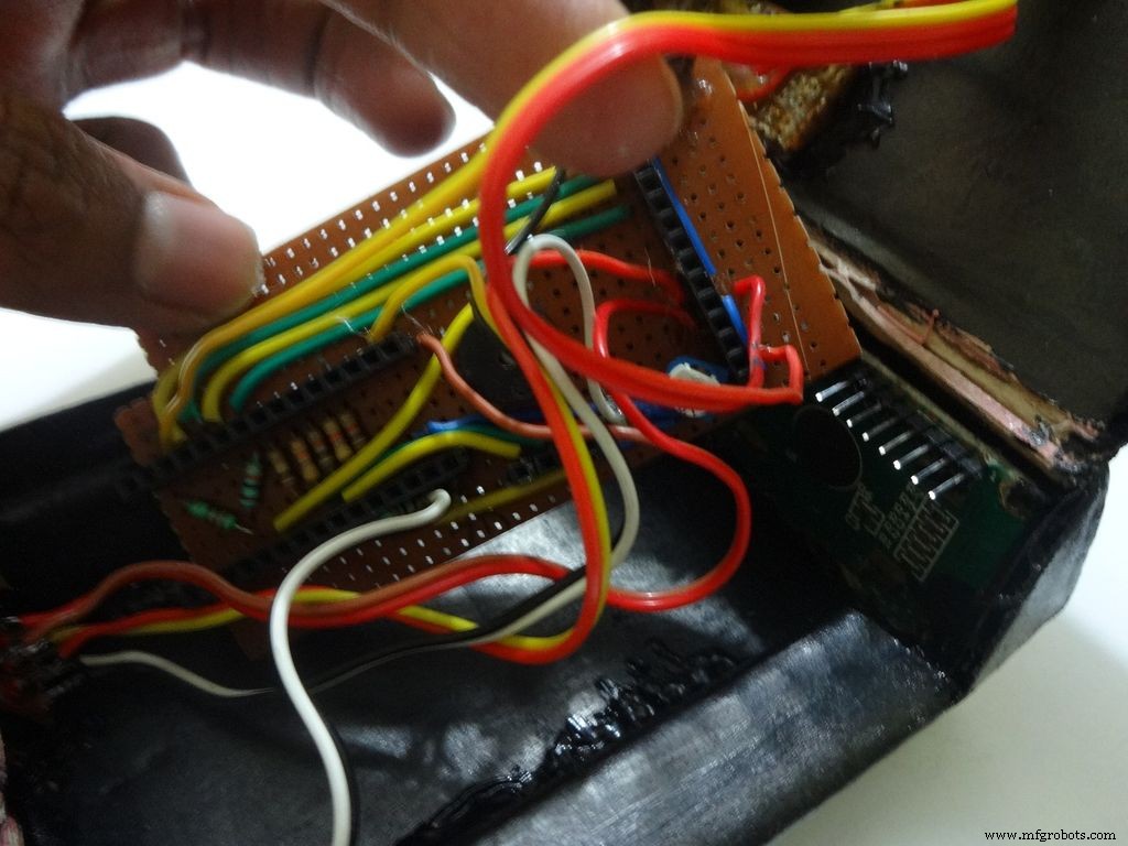
Make sure you refer the circuit design before making any connections.
First connect the reset switch, one end to RST and one end to GND.
Then, the backlight switch. One end to +5V and other end to 'A' or Anode of the backlight LED. Also connect 'K', Cathode to GND.
Next is the RS switch, connect one end to RS and other to pin D1(TX).
And finally the Enable switch. Connect one end to 'E' or Enable and other end to pin D0(RX).
Switches
Where to?
Reset - pushbutton RST and GND Backlight - slide +5V and A RS - slide D1 (TX) and RS Enable - slide D0 (RX) and E
Note:Pins D0 and D1 are connected through switches as keeping them connected sometimes causes problems while using Serial(for debugging).
This completes the base wiring. Apply hot glue after double checking the connections.
Then connect the 3 wires of mode change button:The 10k pulldown resistor to GND. 220 Ohm resistor to pin D11 and input pin to +5V or VCC
Finally connect the 6 wires from the test slots to their appropriate places(shown in images).
Positive
Negative
Resistance Test A7 GND Capacitance Test A0 GND Diode Test A6 D12
Note:All the +5Vs and GNDs are same and hence connect to most convinient spot.
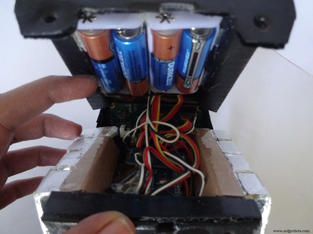
Step 31:Adding the battery case
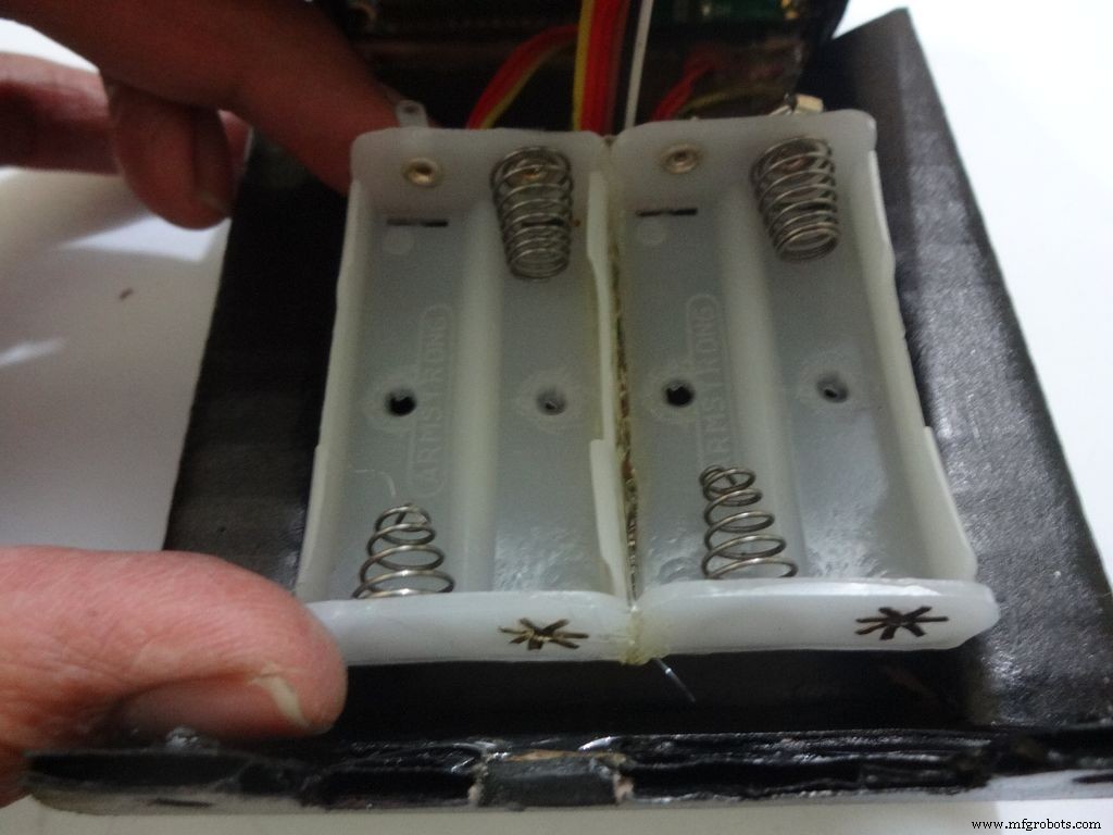
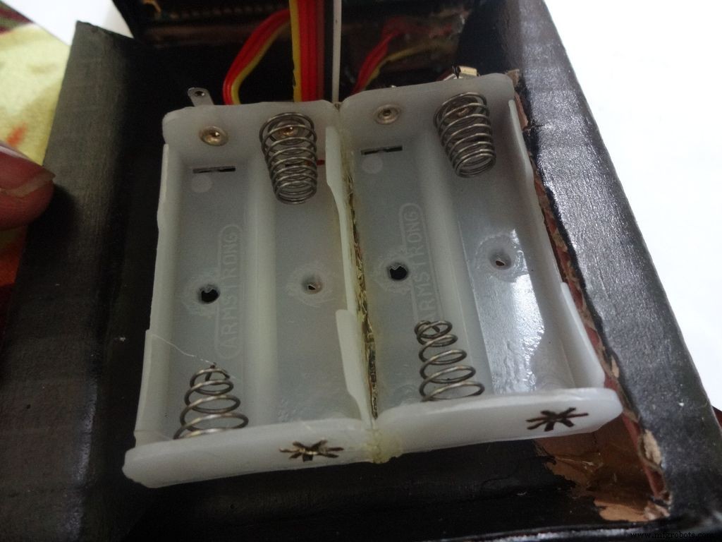

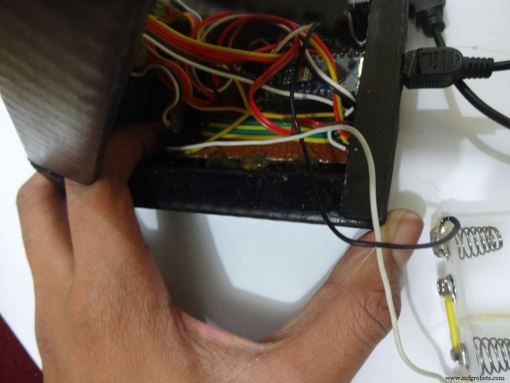
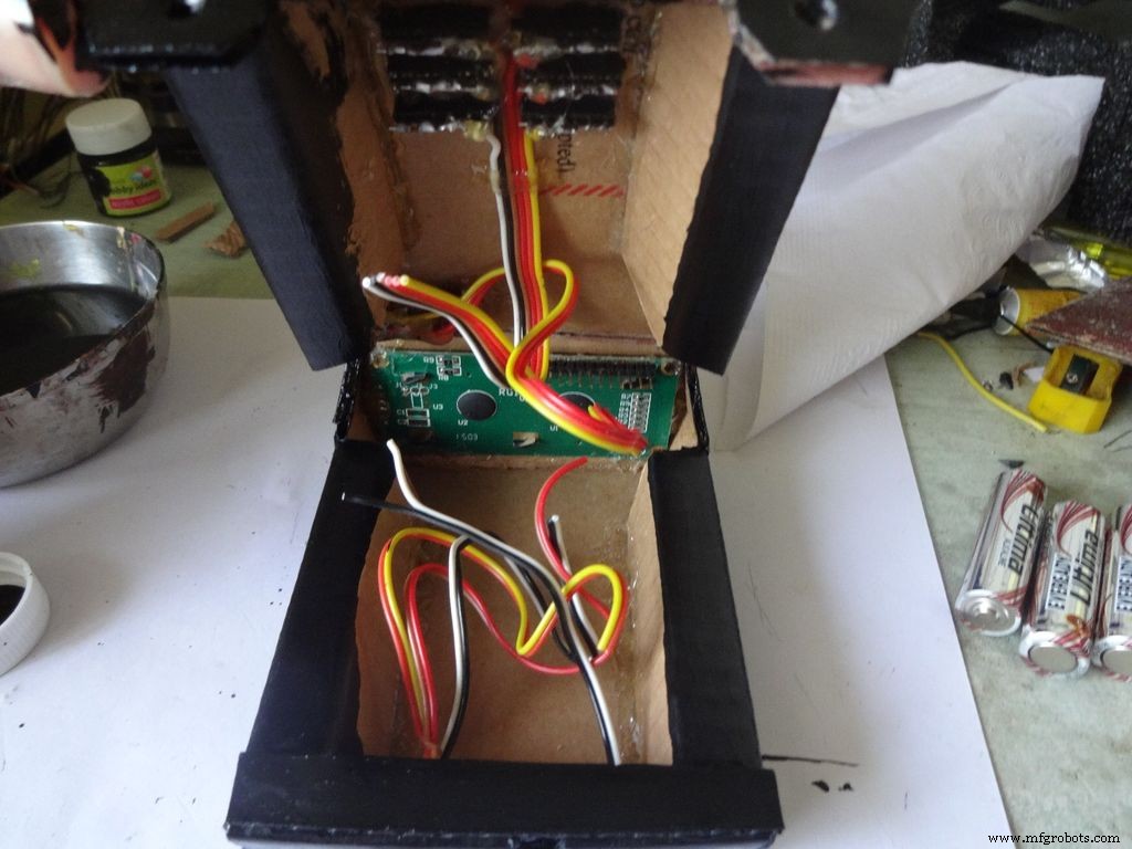
Place the battery case at the top cover, make cuts to place it inside such that the cover can be closed properly.
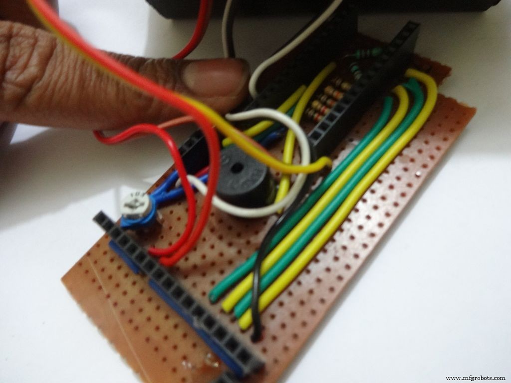
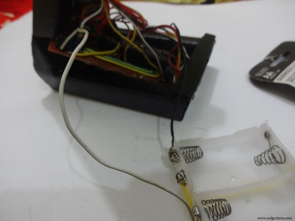
Solder Wires to the case, strip and tin them. Solder the positive end to the middle pin of power switch and negative end to ground.
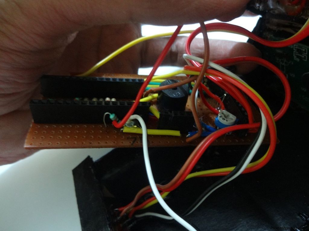
Glue the PCB to the base after making all the connections.
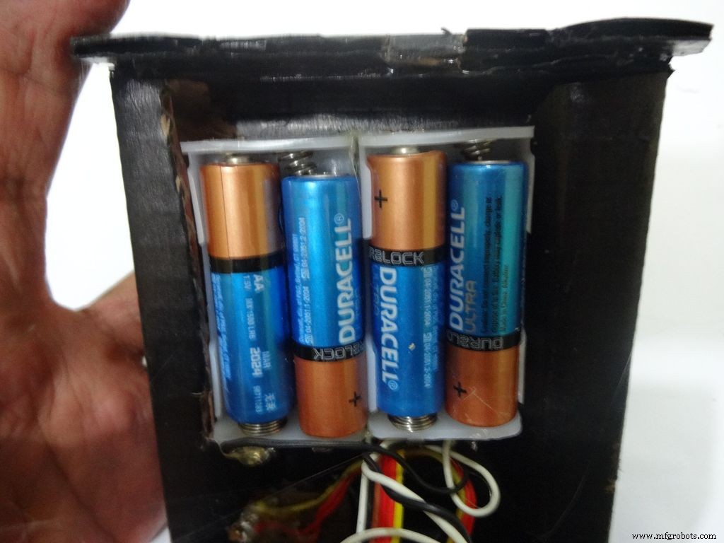
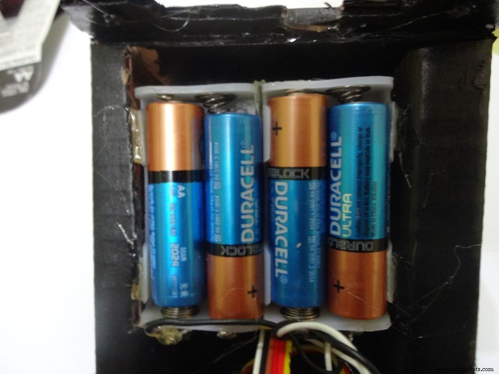
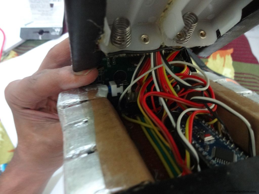
Twist the wires and place them in position. Insert batteries(the case expands a bit on inserting batteries) and glue the case to the cover.
Step 32:Adding the Legs
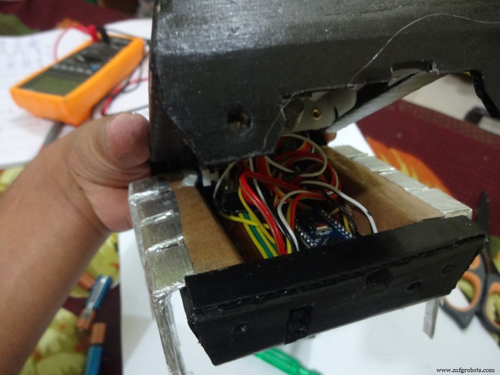
Cut the inner part of legs so that it fits in properly. Stick it it place.
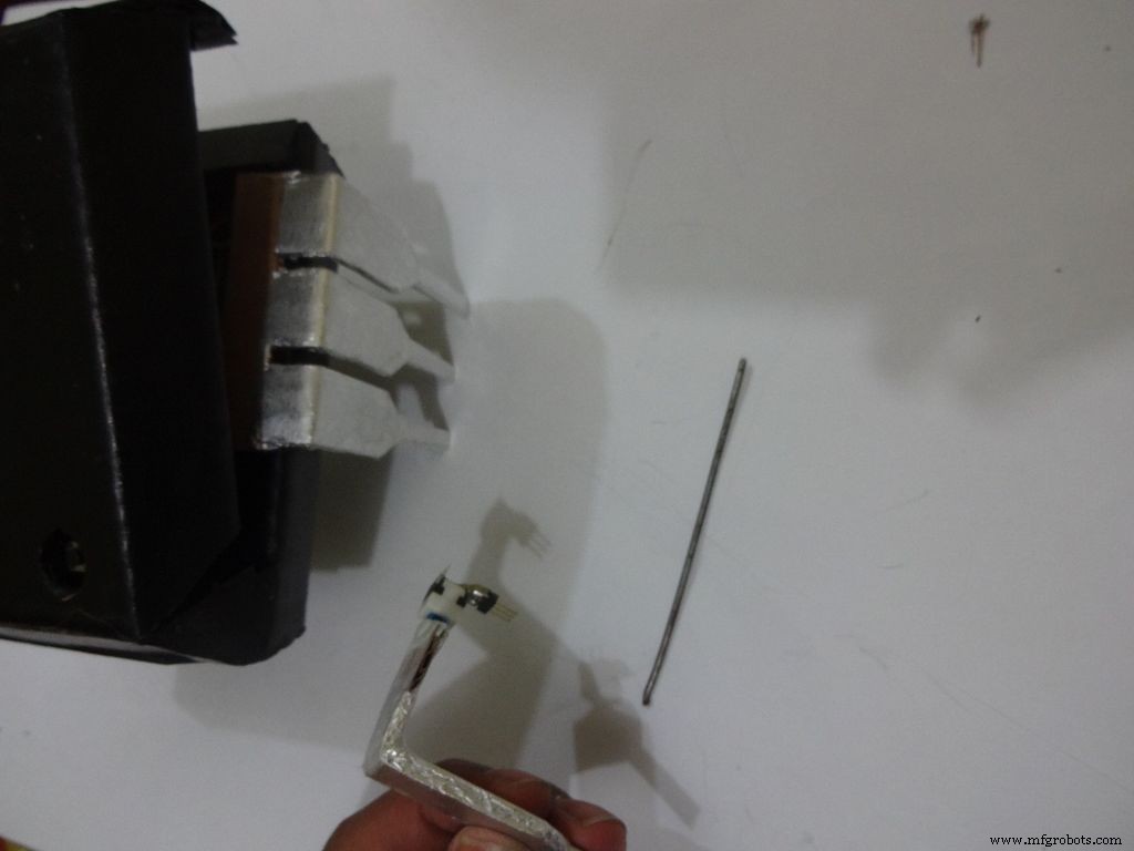
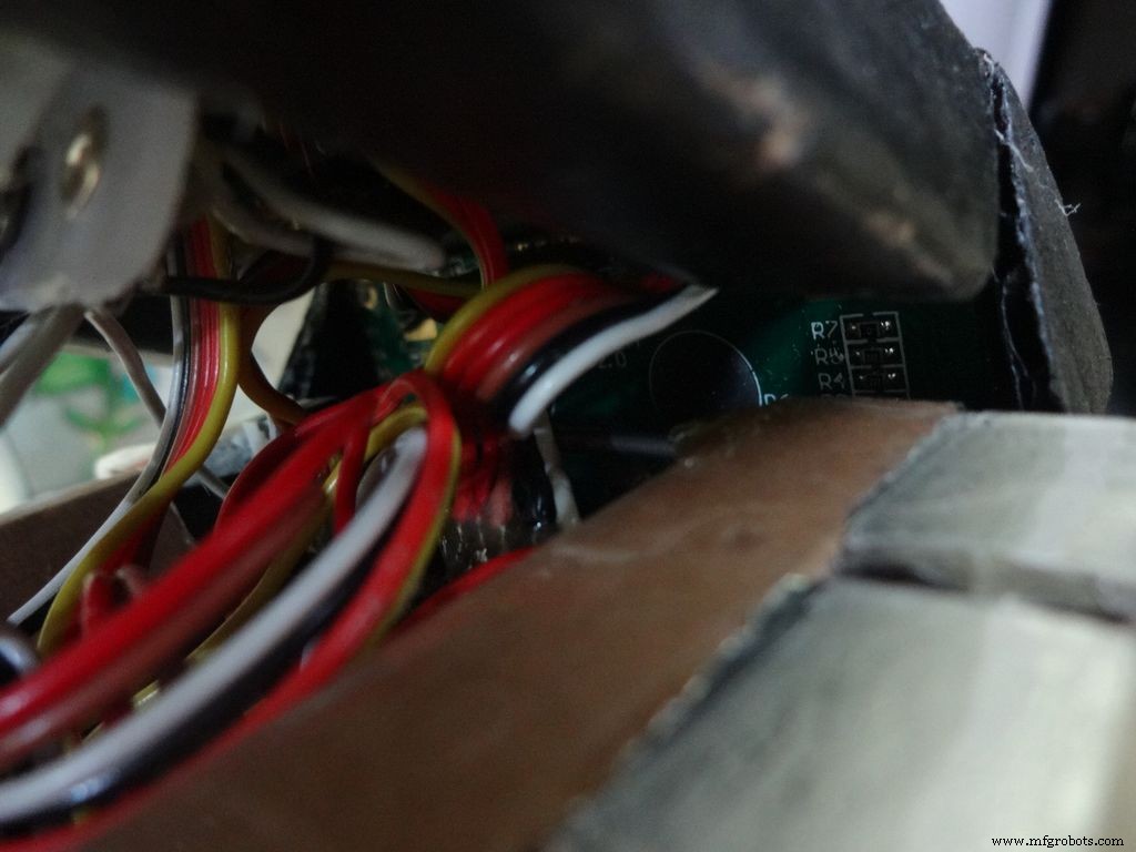
Put the power switch pin in to check if it fits in perfectly. Remove it, add a metal rod, piece of wood or anything strong of proper length that will prevent the switch from moving back. Glue it in place.
Check the switch, it should be turning on/off smoothly.
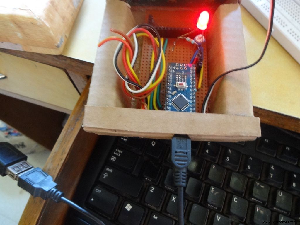
Switch on the IC and test all the functions. If its not working skip to the troubleshooting section.
Step 33:Finishing up!
Use M-seal (or equivalent) to fill any small gaps around the testing area and the mode change button. After drying, sand it well and apply a second layer of paint.
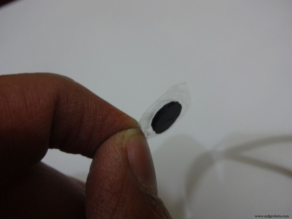
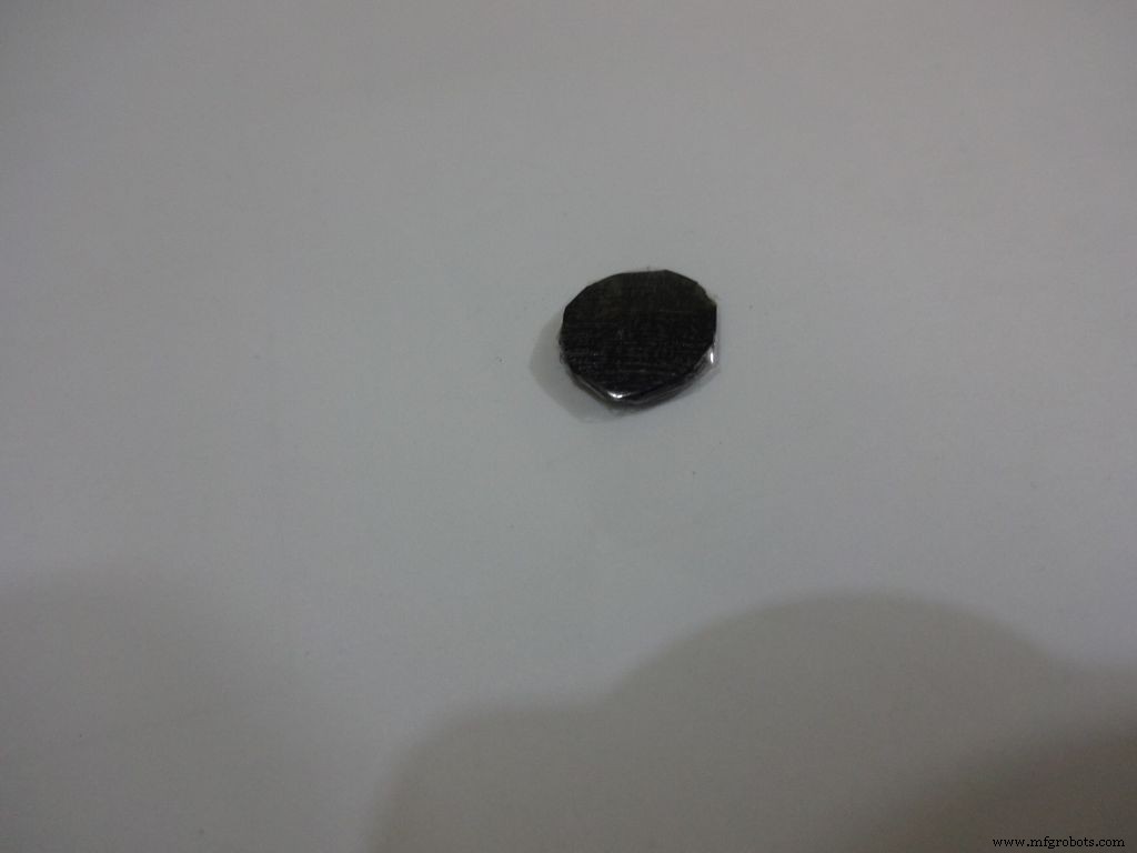
Make the button with a small piece of cardboard, paint it black and cover it with tape(gives a shiny finish). Apply a tiny drop of glue and stick the button in place.
Step 34:Problems and Troubleshooting

Do everything correctly. This is the most boring most of any project and you dont wanna get here just because you soldered the wrong pins!
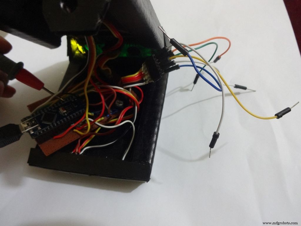
- Recheck every soldered joint and ensure that it isnt touching the adjacent one. Use the multimeter continuity test for help.
- After cutting component/jumper leads make sure the cut lead doesnt fall underneath the PCB. This may lead to unwanted shorting soldered joints.
- Write down anything you need to remember in a book, don't trust your memory.
- If LCD is not displaying, make sure the contrast is adjusted properly. Also make sure the pin0 and 1 switches are turned ON. Check all the pin connections from LCD to Arduino with continuity test. Use breadboard jumpers wherever your mutimeter cant reach.
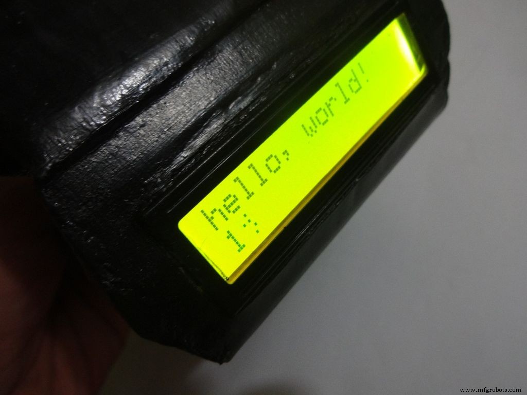
- Upload the hello world LCD program to see if the problem is in the code.
- If a particular function is not working, check its connections and tally it with the code.
- And most importantly, keep your curious pets with their evil minds away from your workspace! :p
Step 35:Things I did, some mistakes I made
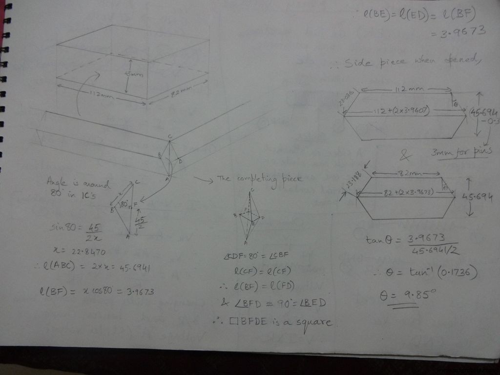

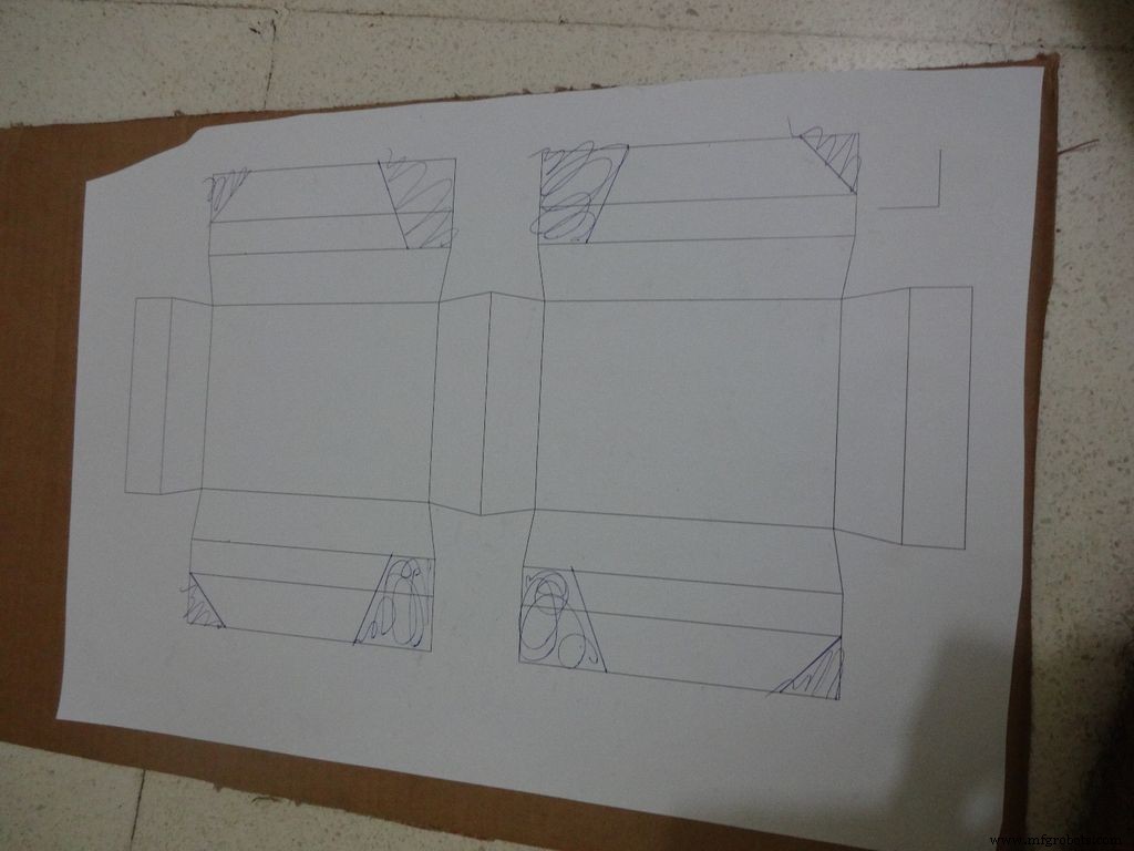
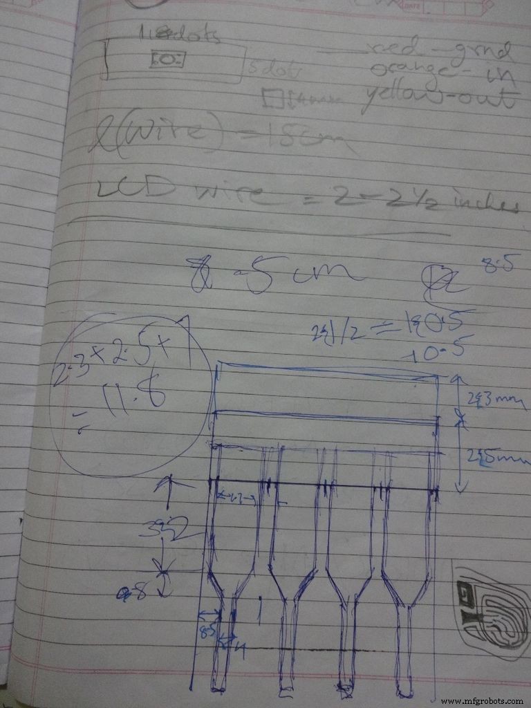
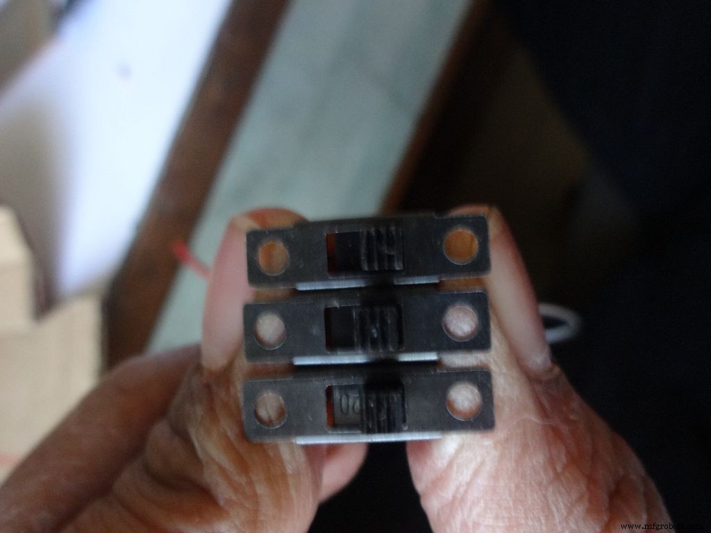
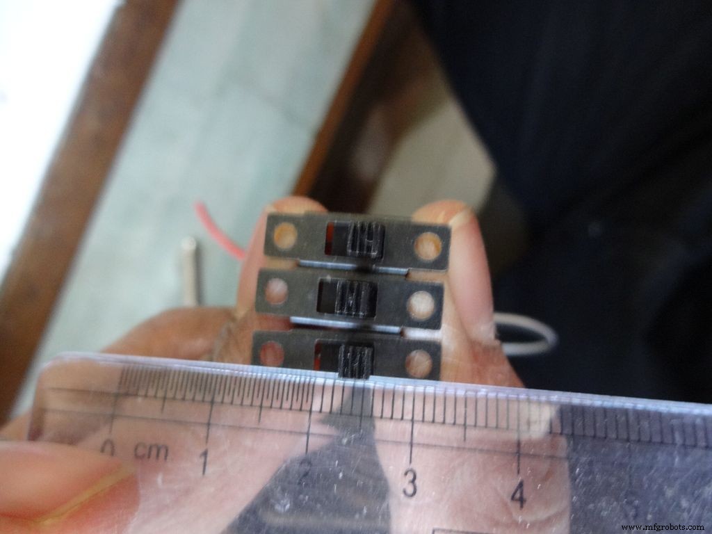
While testing the various circuits and when I had the rough idea of what I want to make, I decided to go with the IC design. I measured actual ICs, took ratios of their lengths, got the angle with some trignometry to be around 80 degrees. Then I decided the inner box length and breadth and built upon it(shown in image). Once the layout was planned, I initially started to draw it accurately on a large size paper. After a bit of a struggle of drawing accurate lines, I realised that this kind of work should be done on a computer! So I learnt CAD basics and succesfully made the layout on it. :) But this layout didnt work out and I had to redo the entire cutting and making of the case.(See images)
While removing the LEDs on the Arduino Nano I used excess pressure to remove a stubborn LED, and ended up removing a PCB pad. Always desolder without forcing/applying pressure on the joints, the pads are delicate and easily come off if you dont stay calm.
When all the solder joints were made and project was about to get finished, in excitement and eagerness, I glued the PCB inside the case before adding the battery case. Had to re-melt the hot glue with a soldering iron (carefully not to melt any wire insulation) and remove the PCB out to solder the battery case wires in. The soldering iron can be cleaned afterwards.
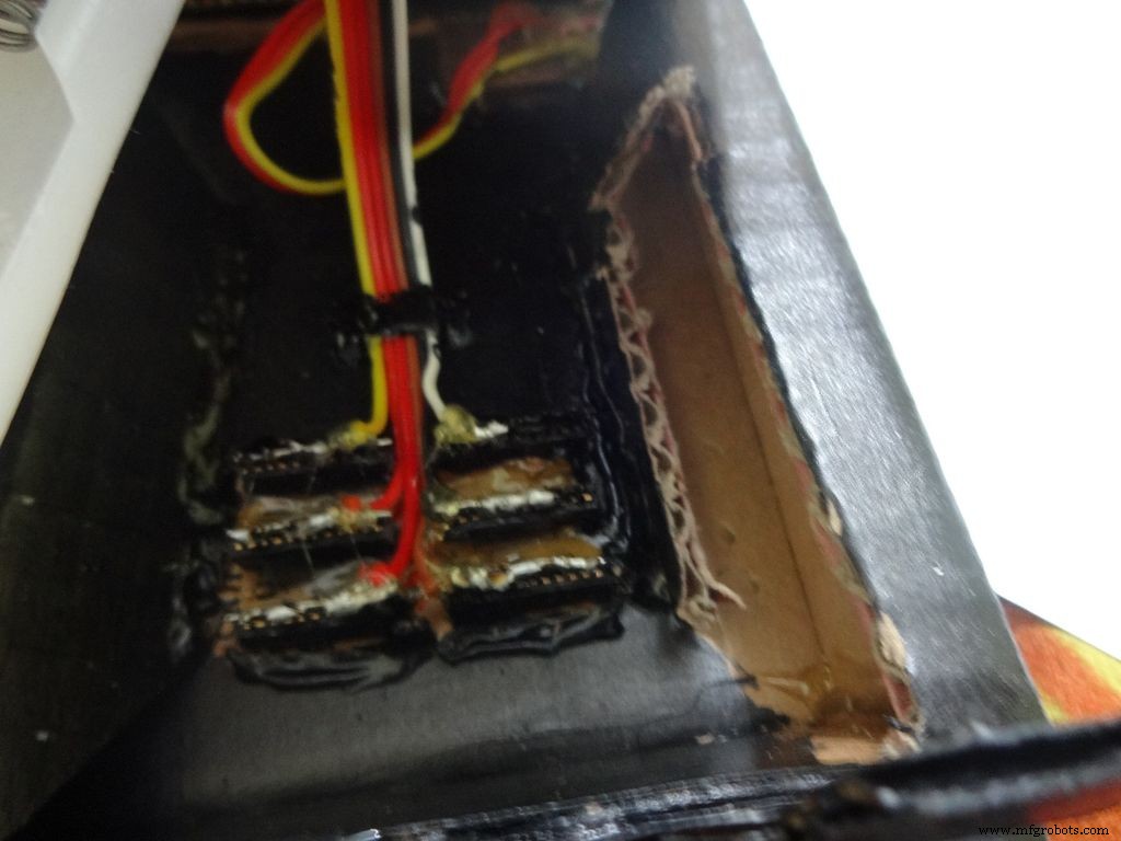
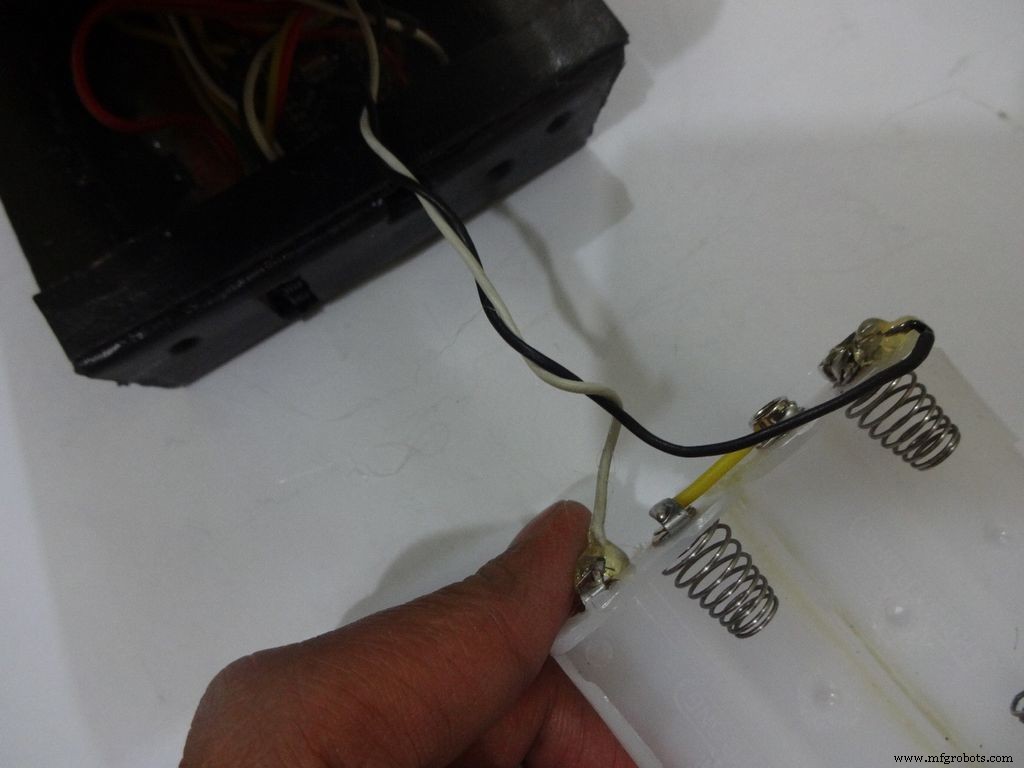
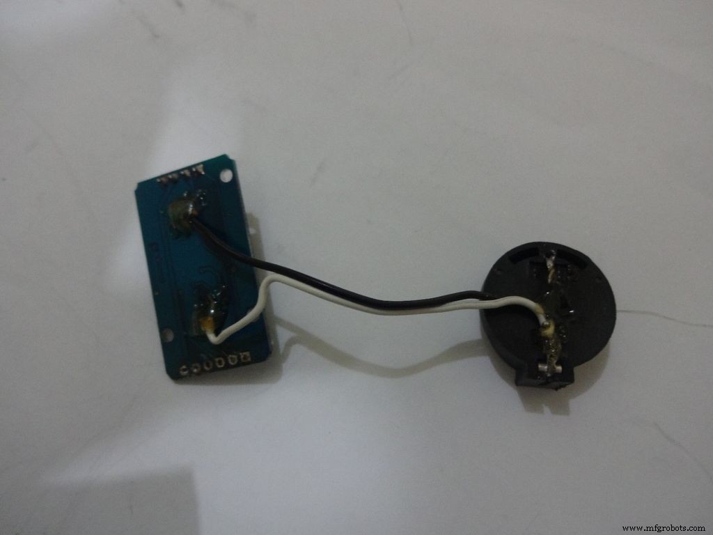
The RTC module battery was coming in way of the batteries while closing and so I separated the battery holder(Warning:desolder only with the battery removed) and added extension wires so that the battery can be placed at the sides where there is space.
All the Layout PDFs, CAD Files and the Main code can be downloaded here:Google Drive
Code
- Extrait de code n° 1
- Code snippet #2
- Extrait de code 3
- Extrait de code n° 4
Extrait de code n°1Texte brut
//Analog pin used to find resistanceint Apin=7;//values of r1 to r5float r1=1000;float r2=4700;float r3=10000;float r4=47000;float r5=100000;//pins of r1 to r5int r1_pin=2;int r2_pin=3;int r3_pin=4;int r4_pin=5;int r5_pin=6;float reading=0; //read from analog pin and store herefloat R=0; //calculate unknown and store hereString finalR; //final value to be displayed along with unitsint caseno; //for debugging, stores the case number // we divide the entire range into cases and assign each a number, // total 5 cases // case1 :less than 2850 // case2 :2850 to 7350 // case3 :7350 to 28500 // case4 :28500 to 73500 // case5 :more than 73500#include// needed for converting float to string, //has the String(float,n) function. Explained below.void setup() { Serial.begin(9600);}void loop() { //first we find unknown resistance using 1kOhm resistor //Therefore, disable R2, R3, R4 and R5 digitalWrite(r2_pin, LOW); //turn each pin to LOW before setting it as INPUT pinMode(r2_pin, INPUT); // turning it to INPUT when its HIGH enables the // internal pullup resistor digitalWrite(r3_pin, LOW); pinMode(r3_pin, INPUT); digitalWrite(r4_pin, LOW); pinMode(r4_pin, INPUT); digitalWrite(r5_pin, LOW); pinMode(r5_pin, INPUT); pinMode(r1_pin, OUTPUT); digitalWrite(r1_pin, HIGH); //read and calculate resistance reading=analogRead(Apin); R=(reading*r1)/(1023-reading); // if value <2850, finalR =value(using 1kOhm) if(R<2850){ caseno=1; if(R<1000){ //if value less than 1000 use "Ohm" not "kOhm" finalR =String(R,2) + "Ohm"; //String(float,n) Converting float to string //with n digits after decimal // attach "Ohm" after value to the string, //'+' joins two strings here } else{ //use "kOhm R=R/1000; finalR =String(R,2) + "kOhm"; } } //if value between 2850 and 7350 , use value obtained by 4.7kOhm else if(R>=2850 &&R<7350){ caseno=2; digitalWrite(r1_pin, LOW); //Enable only 4.7kOhm pinMode(r1_pin, INPUT); digitalWrite(r3_pin, LOW); pinMode(r3_pin, INPUT); digitalWrite(r4_pin, LOW); pinMode(r4_pin, INPUT); digitalWrite(r5_pin, LOW); pinMode(r5_pin, INPUT); pinMode(r2_pin, OUTPUT); digitalWrite(r2_pin, HIGH); reading=analogRead(Apin); R=(reading*r2)/(1023-reading)/1000; finalR =String(R,2) + "kOhm"; } //if value between 7350 and 28500, use value obtained by 10kOhm else if(R>=7350 &&R<28500){ caseno=3; digitalWrite(r1_pin, LOW); pinMode(r1_pin, INPUT); digitalWrite(r2_pin, LOW); pinMode(r2_pin, INPUT); digitalWrite(r4_pin, LOW); pinMode(r4_pin, INPUT); digitalWrite(r5_pin, LOW); pinMode(r5 _pin, INPUT); pinMode(r3_pin, OUTPUT); digitalWrite(r3_pin, HIGH); reading=analogRead(Apin); R=(reading*r3)/(1023-reading)/1000; finalR=String(R,2) + "kOhm"; } //if value between 28500 and 73500, use value obtained by 47kOhm else if(R>=28500 &&R<73500){ caseno=4; digitalWrite(r1_pin, LOW); pinMode(r1_pin, INPUT); digitalWrite(r2_pin, LOW); pinMode(r2_pin, INPUT); digitalWrite(r3_pin, LOW); pinMode(r3_pin, INPUT); digitalWrite(r5_pin, LOW); pinMode(r5_pin, INPUT); pinMode(r4_pin, OUTPUT); digitalWrite(r4_pin, HIGH); reading=analogRead(Apin); R=(reading*r4)/(1023-reading)/1000; finalR =String(R,2) + "kOhm"; } //if value more than 73500, use value obtained by 100kOhm else if(R>=73500){ caseno=5; digitalWrite(r1_pin, LOW); pinMode(r1_pin, INPUT); digitalWrite(r2_pin, LOW); pinMode(r2_pin, INPUT); digitalWrite(r3_pin, LOW); pinMode(r3_pin, INPUT); digitalWrite(r4_pin, LOW); pinMode(r4_pin, INPUT); pinMode(r5_pin, OUTPUT); digitalWrite(r5_pin, HIGH); reading=analogRead(Apin); R=(reading*r5)/(1023-reading)/1000; finalR =String(R,2) + "kOhm"; } Serial.println(finalR); //printing the final string with units Serial.println(" "); retard(1000); }
Extrait de code #2Texte brut
/* RCTiming_capacitance_meter * code concept taken from Paul Badger 2008 * * The capacitor's voltage at one time constant is defined as * 63.2% of the charging voltage. * i.e, A Capacitor is filled to 63.2% of its total capacity in * 1 Time Constant */ int analogPin=0; // analog pin for measuring capacitor voltage int chargePin=7; // pin to charge the capacitor - connected to // one end of the charging resistor int dischargePin=12; // pin to discharge the capacitor, // same used for diode test(checkPin1) float resistorValue=10000.0; // We use 10kOhm resistor unsigned long startTime; unsigned long elapsedTime; float microFarads; // floating point variable to preserve precision float nanoFarads;void setup(){ pinMode(chargePin, OUTPUT); // set chargePin to output digitalWrite(chargePin, LOW); Serial.begin(9600); // initialize serial transmission for debugging}void loop(){ digitalWrite(chargePin, HIGH); // set chargePin HIGH and capacitor charging startTime =millis(); while(analogRead(analogPin) <648){ // just wait and do nothing till 648 // 647 is 63.2% of 1023, // which corresponds to full-scale voltage } elapsedTime=millis() - startTime; // convert milliseconds to seconds ( 10^-3 ) // and Farads to microFarads ( 10^6 ), net 10^3 (1000) microFarads =((float)elapsedTime / resistorValue) * 1000; // (float) converts "unsigned long" elapsed time to float Serial.print(elapsedTime); // print the value to serial port Serial.print(" mS "); // print units if (microFarads> 1){ Serial.print((long)microFarads); // print the value to serial port Serial.println(" microFarads"); // print units } else { // if value is smaller than one microFarad, convert to nanoFarads (10^-9 Farad). nanoFarads =microFarads * 1000.0; // multiply by 1000 to convert to nanoFarads (10^-9 Farads) Serial.print((long)nanoFarads); // print the value to serial port Serial.println(" nanoFarads"); // print units } /* dicharge the capacitor */ digitalWrite(chargePin, LOW); // set charge pin to LOW pinMode(dischargePin, OUTPUT); // set discharge pin to output digitalWrite(dischargePin, LOW); // set discharge pin LOW while(analogRead(analogPin)> 0){ // wait until capacitor is completely discharged } pinMode(dischargePin, INPUT); // set discharge pin back to input} Extrait de code n°3Texte brut
String state ="null"; //prints "null" for reverse bias or nothing connectedint checkPin1 =12;int checkPin2 =6;void setup() { Serial.begin(9600);}void loop() {pinMode(checkPin1, OUTPUT); digitalWrite(checkPin1, LOW); //pin 11 is set to low//analog read is normally pulled up by the 10k resistor, so null reading is 1023//In forward bias, the analog pin gets connected to checkPin1, which is LOW. So reading less than 1023//Practically a small current flows in reverse bias as well, so we take 700 to differentiate if(analogRead(checkPin2)<700){ state="forward"; } Serial.println(state); Serial.println(analogRead(checkPin2)); state ="null"; delay(500);} Extrait de code n°4Texte brut
// Date and time functions using a DS1307 RTC connected via I2C and Wire lib#include #include RTC_DS1307 rtc;//creating "rtc" object of RTC_DS1307, objects are used to access functions //more on objects and classes:https://www.youtube.com/watch?v=ABRP_5RYhqUchar daysOfTheWeek[7][12] ={"Sunday", "Monday", "Tuesday", "Wednesday", "Thursday", "Friday", "Saturday"};void setup () { Serial.begin(9600); rtc.begin(); // following line sets the RTC to the date &time this sketch was compiled // rtc.adjust(DateTime(F(__DATE__), F(__TIME__))); // This line sets the RTC with an explicit date &time, for example to set // January 21, 2014 at 3am you would call:// rtc.adjust(DateTime(2014, 1, 21, 3, 0, 0));}void loop () { DateTime now =rtc.now(); Serial.print(now.year()); Serial.print('/'); Serial.print(now.month()); Serial.print('/'); Serial.print(now.day()); Serial.print(" ("); Serial.print(daysOfTheWeek[now.dayOfTheWeek()]); Serial.print(") "); Serial.print(now.hour()); Serial.print(':'); Serial.print(now.minute()); Serial.print(':'); Serial.print(now.second()); Serial.println(); Serial.println(); delay(1000);} Github
https://github.com/adafruit/RTClibhttps://github.com/adafruit/RTClibSchémas
Main_Schematic.fzzProcessus de fabrication