


Spectrino :TinyML Arduino et solutions sans contact basées sur l'IoT
Composants et fournitures
 |
| × | 1 | |||
 |
| × | 1 | |||
| × | 1 | ||||
| × | 1 | ||||
 |
| × | 1 | |||
 |
| × | 2 | |||
| × | 1 | ||||
| × | 1 | ||||
 |
| × | 1 | |||
 |
| × | 1 | |||
 |
| × | 1 |
Outils et machines nécessaires
 |
|
Applications et services en ligne
 |
| |||
 |
| |||
 |
| |||
 |
|
À propos de ce projet
Aperçu
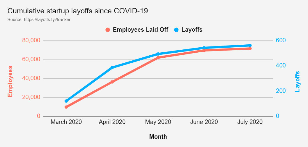
La pandémie a introduit une contrainte aux interactions sociales :la distance. Compte tenu de ce facteur de risque, les pays du monde entier ont été soumis à des niveaux de quarantaine variables et de nombreux centres commerciaux ont dû fermer leurs portes en raison de la nombre de consommateurs considérablement réduit . Cela a conduit à un niveau très, très élevé de licenciements du personnel du centre commercial , ainsi que des défis économiques similaires pour les propriétaires d'entreprise .
Cela a entraîné des niveaux de perte d'emplois à faible revenu relatif (moins de 40 000 $ de revenus annuels) au 2 juillet 2020 aux États-Unis en raison de COVID-19. L'hébergement et les services de restauration, ainsi que le commerce de détail et le divertissement représentent collectivement environ 4 000 000 des emplois perdus.
Le défi économique auquel sont confrontées différentes industries, où l'alimentation, la consommation et la vente au détail figurent dans le Top 6 des industries avec le plus grand nombre d'employés licenciés (soit plus de 20 000 emplois estimés). En supposant que « International » inclue toutes les zones non américaines prises en compte par cette recherche, le nombre total de licenciements dans le monde atteint environ 103 000 emplois.
COMPLICATION
Compte tenu des données fournies, l'équipe a déterminé qu'un défi majeur est qu'il existe une incertitude de risque, en ce qui concerne la densité de population dans les différents magasins, pour les centres commerciaux encore ouverts. En dehors de cela, bien que le port de masques faciaux et l'évitement du toucher soient obligatoires dans de nombreux endroits, il y a toujours des violations. Cela rend plus difficile pour le personnel du centre commercial et les propriétaires d'entreprise, qui ne peuvent pas se permettre de travailler à distance, de naviguer en toute sécurité dans ce nouvel espace de travail normal. Cela soulève la question :comment pouvons-nous garantir à un niveau de certitude décent qu'à tout moment, un magasin particulier du centre commercial peut entrer en toute sécurité ?
Nous luttons tous maintenant contre la pandémie actuelle de COVID-19. Et aussi, maintenant nous sommes dans une situation où nous devons nous adapter aux conditions du moment avec plus de mesures de sécurité. Alors que la vie revient à la normale avec davantage de mesures de sécurité pour éviter l'infection virale, l'ajout de sécurité dans les lieux publics et les zones surpeuplées prévaut également dans les villes. Mais il y a eu de nombreuses situations où nous devons enfreindre les mesures de sécurité et interagir avec un élément dangereux pour répondre aux nécessiteux. Ici, le projet traite de la prévention de la propagation du COVID-19 par le biais d'interactions tactiles ou de touchers.
Une expérience avait été menée pour voir la propagation de tout virus par le toucher. Les résultats ont été évalués comme suit :
J'ai donc décidé d'automatiser les appareils les plus couramment utilisés dans les logements et les sociétés pour assurer une communication mains libres avec les appareils.
Les solutions suivantes ont été développées pour réaliser ce prototype
- Système d'interphone intelligent utilisant TinyML déployé sur Arduino33 BLE Sense : Ce qui suit sera une solution sans contact utilisant Computer Vision et un modèle TinyML pour détecter une personne à l'extérieur de la porte et faire sonner la cloche sans que la personne ne touche la cloche.
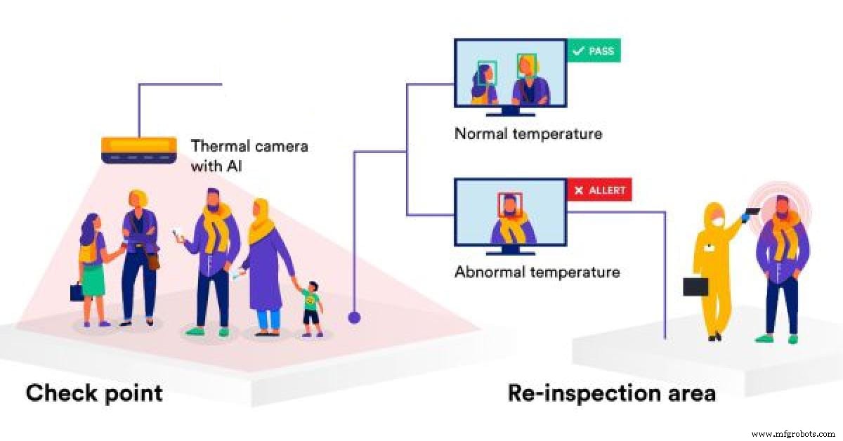
- Système de surveillance de la température Utilisation de l'IoT et du système d'alerte : Au milieu de la pandémie, la sécurité est devenue un aspect important. Par conséquent, le système de surveillance de la température utilise le tableau de bord IoT Thingspeak et détecte les personnes lorsqu'elles entrent et mesure leur température. Cette température est affichée sur un tableau de bord IoT pour les tendances et l'analyse des données en temps opportun. En cas de détection de température anormale, des alertes sont générées sur lesquelles la personne subit une deuxième inspection.
- Système d'ascenseur sans contact utilisant le modèle TinyML de reconnaissance vocale sur Arduino BLE 33 sense : Nous utilisons des ascenseurs pour monter ou descendre dans un immeuble plusieurs fois par jour, et j'ai toujours peur de toucher des interrupteurs contaminés qui ont été touchés par d'autres personnes en train de se déplacer. Par conséquent, ce modèle de reconnaissance vocale identifiera quand une personne souhaite monter ou descendre et effectuera de la même manière l'action.
- Système de détection MaskModel basé sur TinyML et système de surveillance IoT : Cette méthode utilisera un modèle de vision par ordinateur déployé sur Arduino BLE 33 sense pour détecter si une personne a porté un masque ou non. De même, ces données sont envoyées à un tableau de bord IoT pour surveiller et imposer des restrictions en fonction des moments dangereux.
- Système de surveillance et d'établissement de files d'attente intelligentes dans un supermarché ou un centre commercial à l'aide de TinyML, de l'IoT et de la vision par ordinateur : Ce modèle détectera une personne debout à l'extérieur du supermarché et permettra l'entrée de 50 personnes à la fois dans le supermarché. Il attendra encore 15 minutes pour laisser les personnes à l'intérieur terminer leurs achats et permettre à nouveau au prochain groupe de 50 personnes d'entrer dans le centre commercial. Cela se fera à l'aide de la vision par ordinateur et de TinyML déployé sur un sens Arduino 33 BLE. Ces données seront ensuite projetées sur un tableau de bord IoT où les données en temps réel peuvent être suivies.
- Système de surveillance des personnes dans une allée d'un centre commercial et système de désinfection basé sur la contamination :Cette solution utilise un algorithme de détection de personne déployé dans une zone d'un centre commercial ou d'un supermarché et si la contamination de la personne dans une zone a dépassé le seuil, elle auto-assainit la zone avec une lumière UV. La période et les heures de désinfection sont projetées sur un tableau de bord IoT pour le personnel du supermarché à des fins d'analyse.
Mise en place (Exigences pour le projet) :
Matériel requis :
1)sens Arduino33BLE
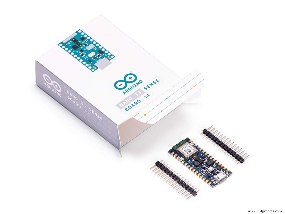
L'Arduino Nano 33 BLE Sense est une évolution de l'Arduino Nano traditionnel, mais doté d'un processeur beaucoup plus puissant, le nRF52840 de Nordic Semiconductors, un processeur ARM® Cortex™-M4 32 bits fonctionnant à 64 MHz. Cela vous permettra de faire des programmes plus gros qu'avec l'Arduino Uno (il a 1 Mo de mémoire programme, 32 fois plus gros), et avec beaucoup plus de variables (la RAM est 128 fois plus grande). Le processeur principal comprend d'autres fonctionnalités étonnantes telles que l'appairage Bluetooth® via NFC et des modes à très faible consommation d'énergie.
Intelligence Artificielle Embarquée
La principale caractéristique de cette carte, outre la sélection impressionnante de capteurs, est la possibilité d'y exécuter des applications Edge Computing (IA) en utilisant TinyML. Vous pouvez créer vos modèles d'apprentissage automatique à l'aide de TensorFlow™ Lite et les télécharger sur votre carte à l'aide de l'IDE Arduino.
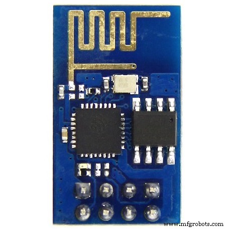
2)ESP8266 ESP-01
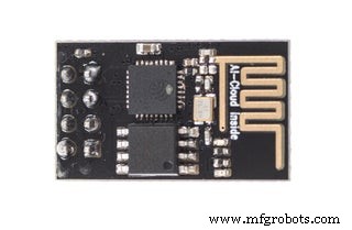
L'ESP8266 ESP-01 est un module Wi-Fi qui permet aux microcontrôleurs accès à un réseau Wi-Fi . Ce module est un SOC autonome (System On a Chip) qui n'a pas nécessairement besoin d'un microcontrôleur pour manipuler les entrées et les sorties comme vous le feriez normalement avec un Arduino , par exemple, parce que l'ESP-01 agit comme un petit ordinateur. Selon la version de l'ESP8266, il est possible d'avoir jusqu'à 9 GPIO (General Purpose Input Output). Ainsi, nous pouvons donner à un microcontrôleur un accès Internet comme le fait le bouclier Wi-Fi à l'Arduino, ou nous pouvons simplement programmer l'ESP8266 non seulement pour avoir accès à un réseau Wi-Fi, mais aussi pour agir comme un microcontrôleur. Cela rend l'ESP8266 très polyvalent.
3)Arducam Mini 2MP plus
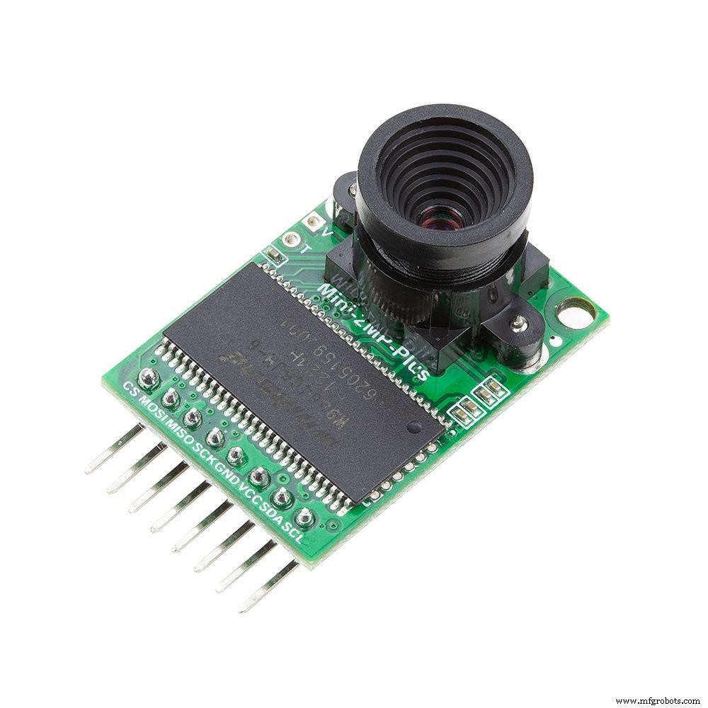
ArduCAM-2MP-Plus est une version optimisée du shield ArduCAM Rev.C, et est une caméra SPI 2MP haute définition, ce qui réduit la complexité de l'interface de contrôle de la caméra. Il intègre le capteur d'image CMOS 2MP OV2640 et fournit une taille miniature, ainsi qu'une interface matérielle facile à utiliser et une bibliothèque de code source ouverte.
L'ArduCAM mini peut être utilisé sur n'importe quelle plate-forme comme Arduino, Raspberry Pi, Maple, Chipkit, Beaglebone black, à condition qu'ils aient une interface SPI et I2C et qu'ils puissent être bien couplés avec des cartes Arduino standard. ArduCAM mini offre non seulement la possibilité d'ajouter une interface de caméra qui n'est pas présente dans certains microcontrôleurs à faible coût, mais offre également la possibilité d'ajouter plusieurs caméras à un seul microcontrôleur.
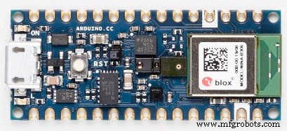
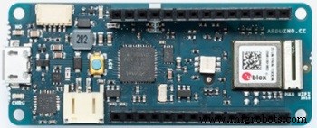
4) Arduino MKR WiFi 1010 :
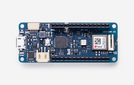
L'Arduino MKR WiFi 1010 est le point d'entrée le plus simple pour la conception d'applications IoT et pico-réseau de base. Que vous cherchiez à créer un réseau de capteurs connecté à votre bureau ou à votre routeur domestique, ou si vous souhaitez créer un appareil BLE envoyant des données à un téléphone portable, le MKR WiFi 1010 est votre solution unique pour de nombreuses applications IoT de base. scénarios.
Le processeur principal de la carte est un SAMD21 32 bits Arm® Cortex®-M0 à faible consommation, comme dans les autres cartes de la famille Arduino MKR. La connectivité WiFi et Bluetooth® est réalisée avec un module de u-blox, le NINA-W10, un chipset basse consommation fonctionnant dans la gamme 2,4 GHz. En plus de cela, une communication sécurisée est assurée via la puce cryptographique Microchip® ECC508. En plus de cela, vous pouvez trouver un chargeur de batterie et une LED RGB orientable à bord.
Outils logiciels :
1)Éditeur Web Arduino
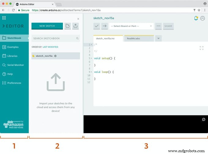
Arduino Create est une plate-forme en ligne intégrée qui permet aux créateurs et aux développeurs professionnels d'écrire du code, d'accéder au contenu, de configurer des cartes et de partager des projets. Passez d'une idée à un projet IoT terminé plus rapidement que jamais. Avec Arduino Create, vous pouvez utiliser un IDE en ligne, connecter plusieurs appareils avec le cloud Arduino IoT, parcourir une collection de projets sur Arduino Project Hub et vous connecter à distance à vos cartes avec Arduino Device Manager. Vous pouvez également partager vos créations, ainsi que des guides étape par étape, des schémas, des références et recevoir les commentaires des autres.
2)Edge Impulse Studio :
La tendance à exécuter ML sur des microcontrôleurs est parfois appelée Embedded ML ou Tiny ML. TinyML a le potentiel de créer de petits appareils capables de prendre des décisions intelligentes sans avoir à envoyer de données vers le cloud, ce qui est formidable du point de vue de l'efficacité et de la confidentialité. Même de puissants modèles d'apprentissage en profondeur (basés sur des réseaux de neurones artificiels) atteignent désormais les microcontrôleurs. Au cours de l'année écoulée, de grands progrès ont été réalisés pour rendre les modèles d'apprentissage en profondeur plus petits, plus rapides et exécutables sur du matériel embarqué grâce à des projets tels que TensorFlow Lite pour les microcontrôleurs, uTensor et Arm's CMSIS-NN ; mais créer un ensemble de données de qualité, extraire les bonnes fonctionnalités, former et déployer ces modèles peut toujours être compliqué.
En utilisant Edge Impulse, vous pouvez désormais collecter rapidement des données de capteurs du monde réel, former des modèles ML sur ces données dans le cloud, puis déployer le modèle sur votre appareil Arduino. À partir de là, vous pouvez intégrer le modèle dans vos croquis Arduino avec un seul appel de fonction. Vos capteurs sont alors beaucoup plus intelligents, capables de donner un sens à des événements complexes dans le monde réel. Les exemples intégrés vous permettent de collecter des données à partir de l'accéléromètre et du microphone, mais il est facile d'intégrer d'autres capteurs avec quelques lignes de code.
3) Le langage des choses :
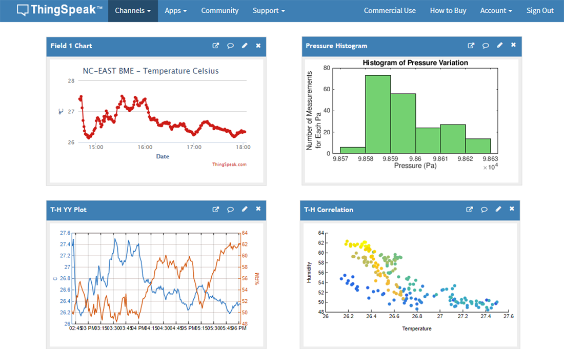
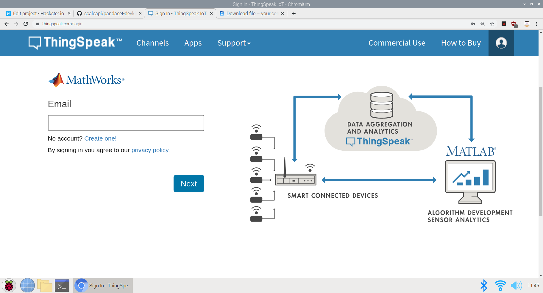
ThingSpeak™ est un service d'analyse IoT qui vous permet d'agréger, de visualiser et d'analyser des flux de données en direct dans le cloud. ThingSpeak fournit des visualisations instantanées des données publiées par vos appareils sur ThingSpeak. Grâce à la possibilité d'exécuter du code MATLAB® dans ThingSpeak, vous pouvez effectuer une analyse en ligne et traiter les données au fur et à mesure qu'elles arrivent. ThingSpeak est souvent utilisé pour le prototypage et la validation des systèmes IoT qui nécessitent des analyses.
Vous pouvez envoyer des données depuis n'importe quel appareil connecté à Internet directement à ThingSpeak à l'aide d'une API Rest ou MQTT. De plus, les intégrations cloud à cloud avec The Things Network, Senet, la passerelle Libelium Meshlium et Particle.io permettent aux données des capteurs d'atteindre ThingSpeak via LoRaWAN® et les connexions cellulaires 4G/3G.
Premiers pas avec les implémentations :
1er projet :système d'ascenseur sans contact utilisant le modèle TinyML de reconnaissance vocale sur Arduino BLE 33 sense :
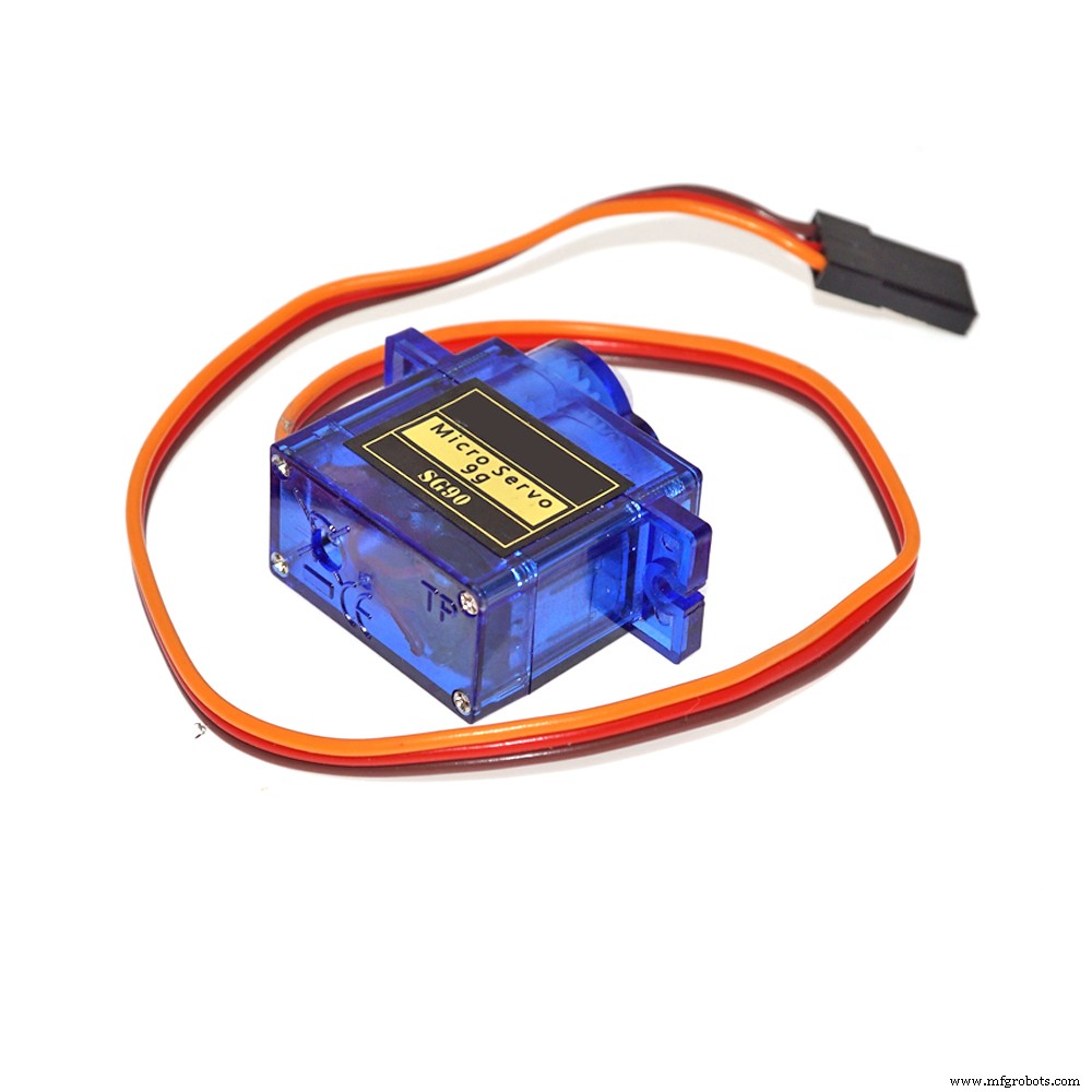
Pendant nos déplacements, nous utilisons les ascenseurs plusieurs fois par jour ! Un interrupteur couramment utilisé est contaminé par tous ceux qui ont déjà touché l'ascenseur plus tôt. J'ai donc décidé de créer une solution sans contact pour les ascenseurs qui utilise des commandes vocales et sans l'utilisation de réseau IoT ou Wifi, elle collabore et exécute l'action. Des solutions de systèmes d'ascenseur sans contact ont été mises en œuvre qui utilisent le contrôle gestuel ou des capteurs à ultrasons pour effectuer des opérations, mais le problème rencontré par ces capteurs est qu'ils doivent être activés à une distance plus proche et, par conséquent, le risque de toucher est augmenté. De plus, ces capteurs sont très sensibles et sont activés même si de petits objets gênent et les activent. En conséquence, j'ai proposé de créer une solution plus précise en utilisant la détection vocale sur le sens Arduino 33 BLE. Ce modèle prend en deux commandes, soit "up" ou "bas" et envoie en conséquence des données au servo pour pousser les boutons respectifs sur le commutateur. L'idée d'envoyer les données au servomoteur pour activer les commutateurs est due au fait qu'un nombre majoritaire de sociétés ont des systèmes de commutateurs et d'affichage pré-construits et donc n'entravent pas ces systèmes préexistants, ceci est créé pour ajouter un système matériel externe pour contrôler les fonctions.
La logique de base utilisée pour exécuter cette fonction est :
Entraînement du modèle à interpréter les commandes « haut » et « Voix » sur Edge Impulse Studio
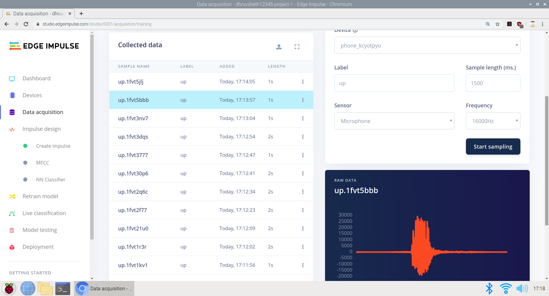
a) Accumuler des données brutes avec des ensembles de données d'entraînement et de test. Ici, j'ai accumulé des données de 1:30min avec chaque durée de données de "up" et "down" de 2sec.
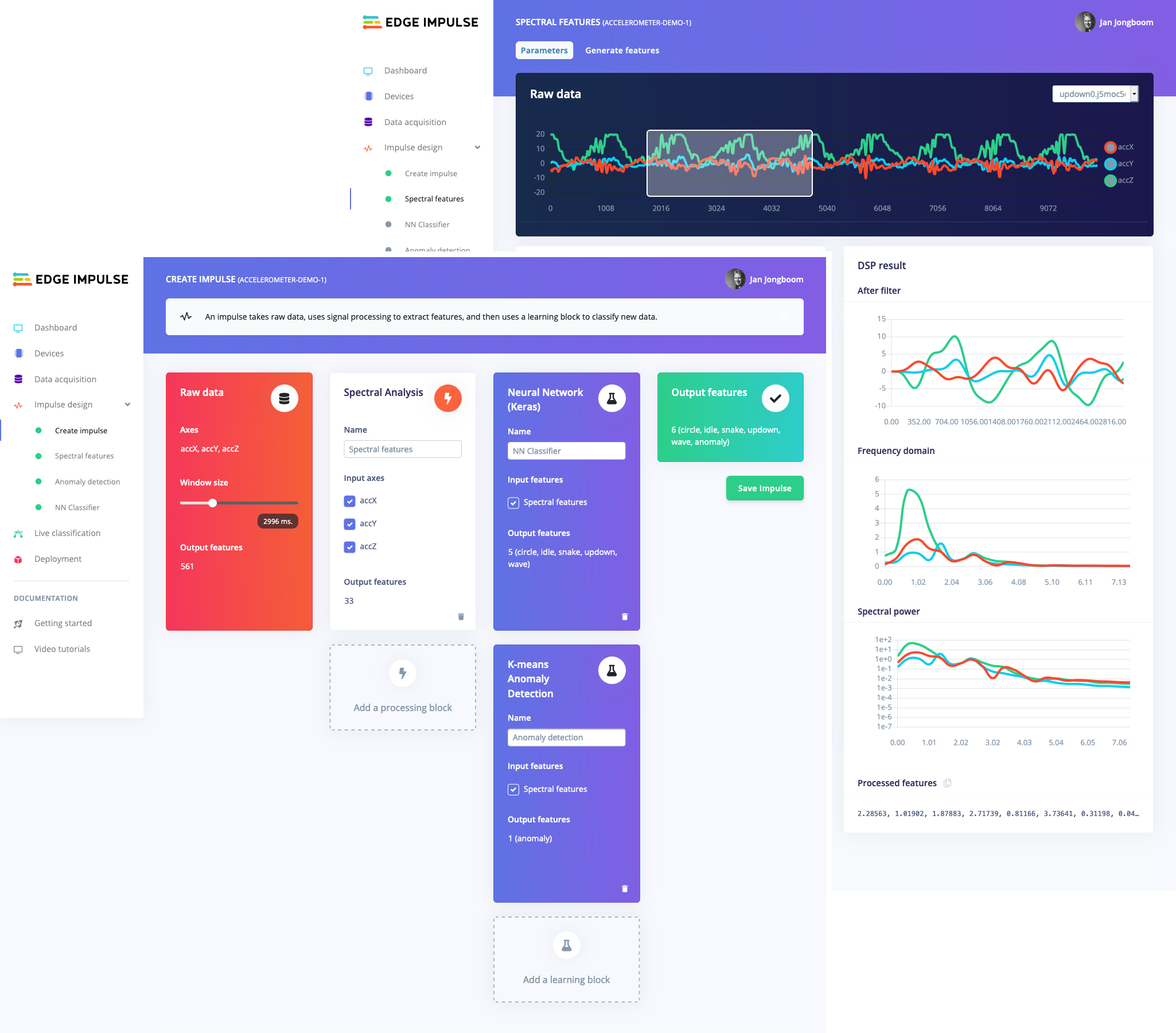
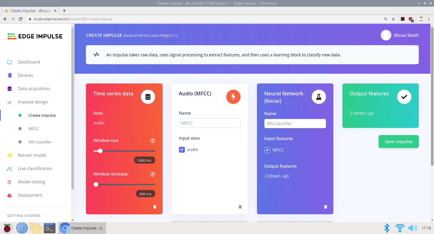
b) Création d'une impulsion basée sur les paramètres requis :
Ici, j'ai défini la taille d'incrément de la fenêtre sur 300 ms et la formation basée sur Keras Neural Network, qui est dédié aux données du microphone et de l'accéléromètre.
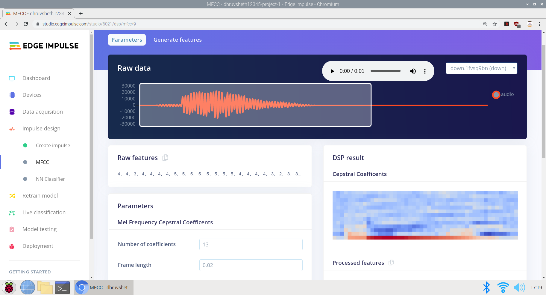
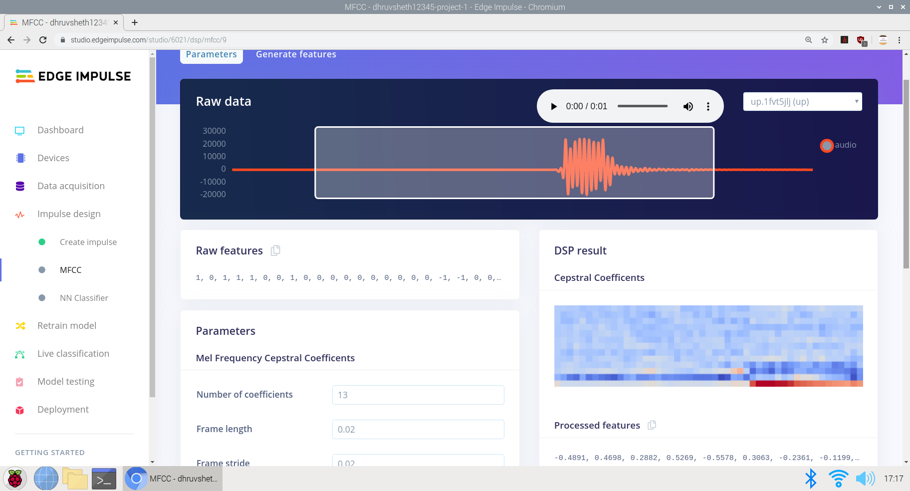
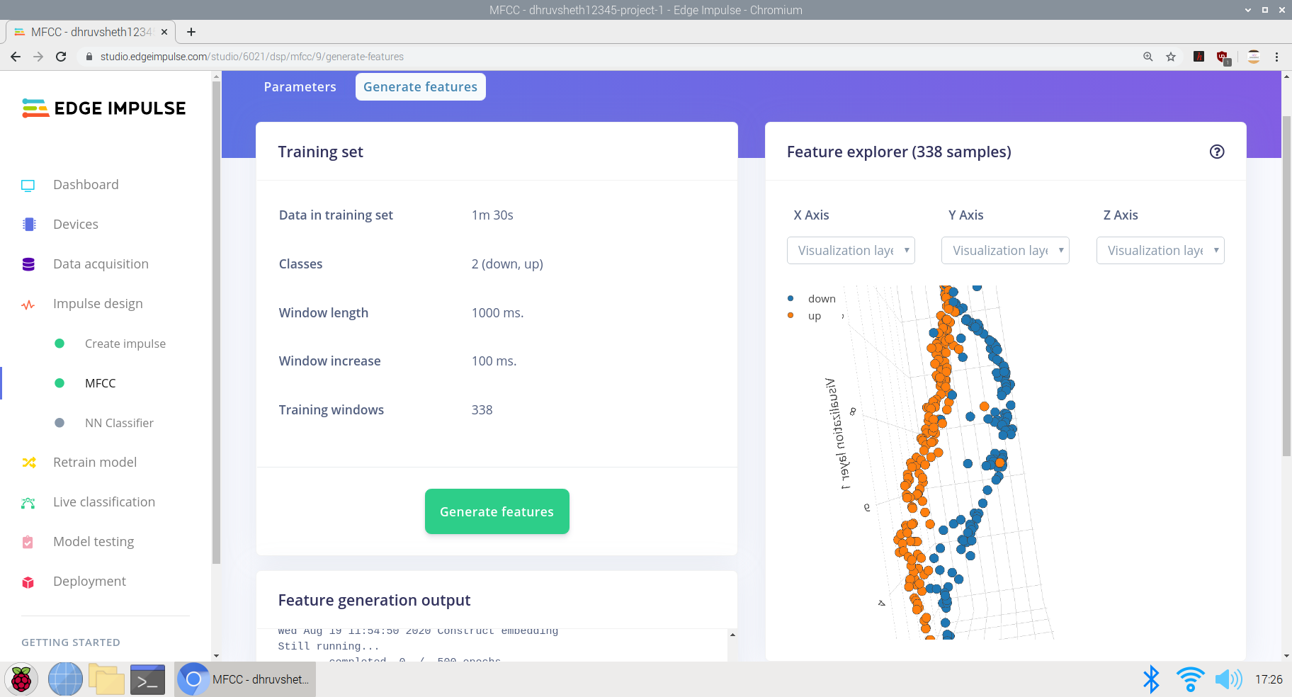
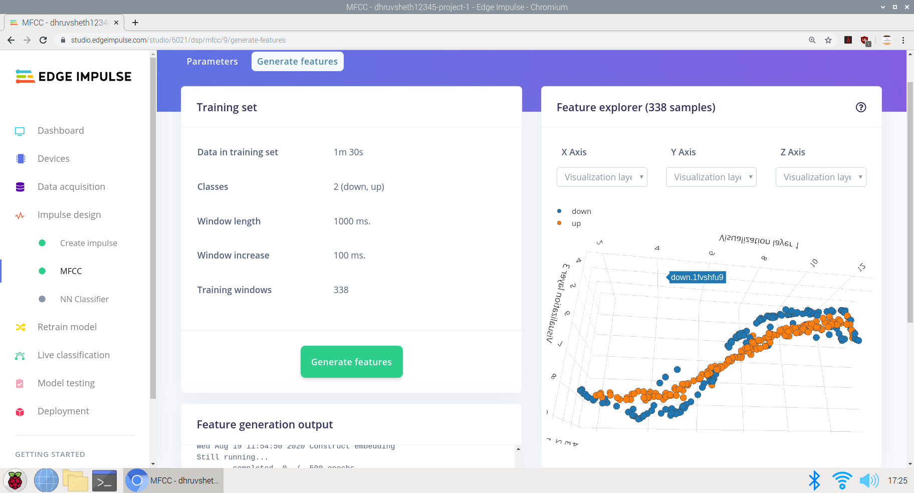
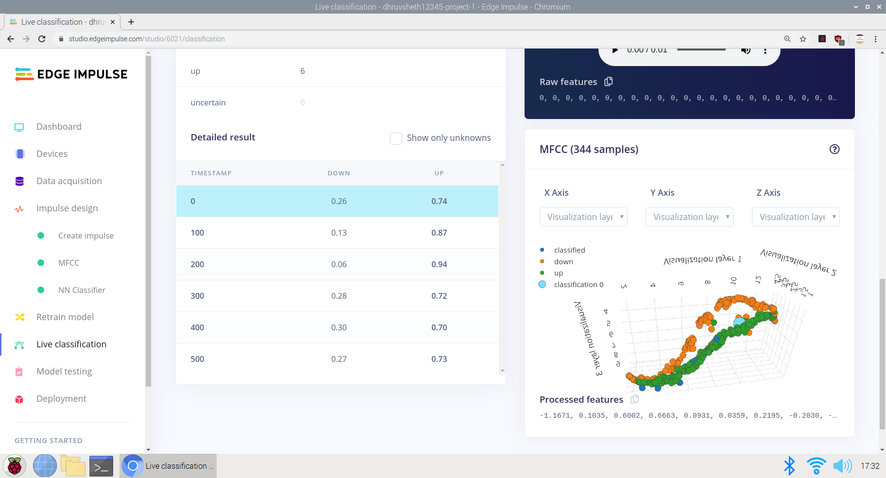
c) Conversion des données brutes en données traitées. Juste en dessous des données brutes, nous pouvons voir les caractéristiques des données brutes et les données traitées sont considérées comme des résultats DSP basés sur des coefficients cepstraux.
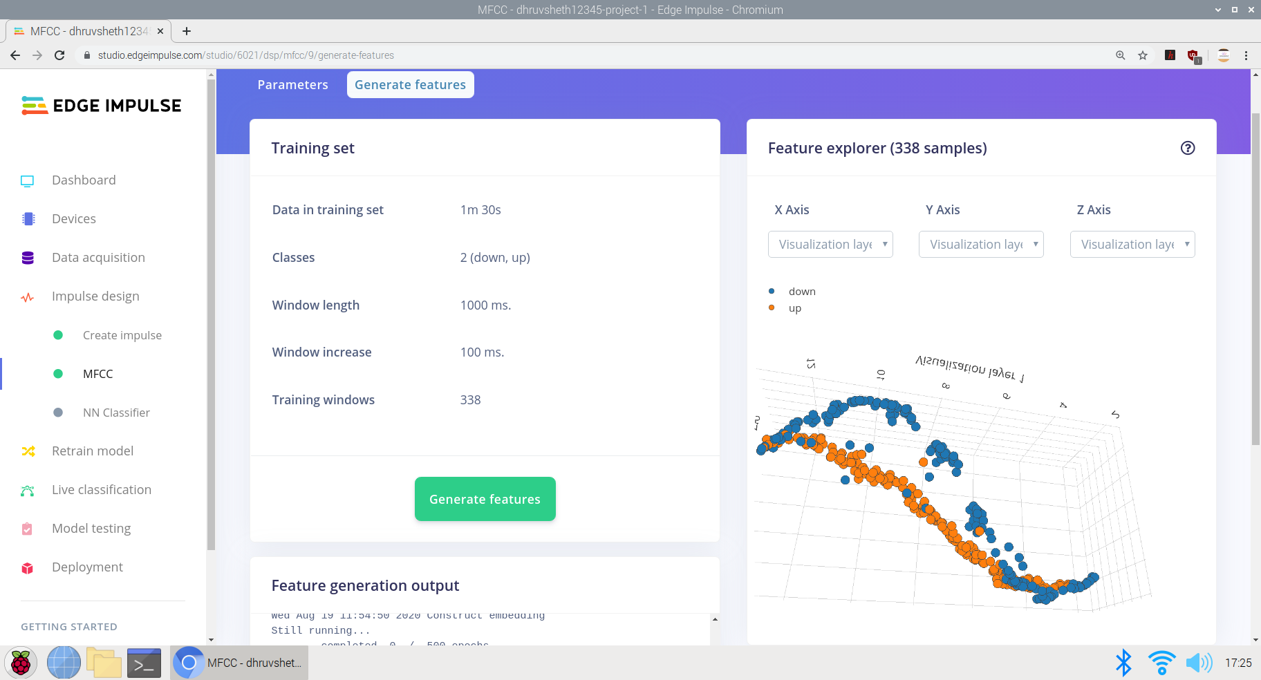
d) Formation des données d'entrée pour générer des caractéristiques traitées. J'ai enregistré les données à basse et haute fréquence sur la base des mêmes données pour mieux entraîner l'impulsion et rendre la reconnaissance vocale précise en l'entraînant sur tous les types de voix. Ici, nous obtenons une sortie de caractéristique dans une courbe "S" avec une différenciation centrale sur les axes x, y et z.
e) Enfin, concevoir une architecture de réseau neuronal dans le classificateur de réseau neuronal Edge Impulse et entraîner le réseau.
Ici, l'architecture de réseau neuronal conçue pour l'entrée de données est la suivante :
- Couche d'entrée
- Remodeler le calque
- Couche de pool de convo 1D (30 neurones, 5 noyaux)
- Couche de pool de convo 1D (10 neurones, 5 noyaux)
- Aplatir le calque
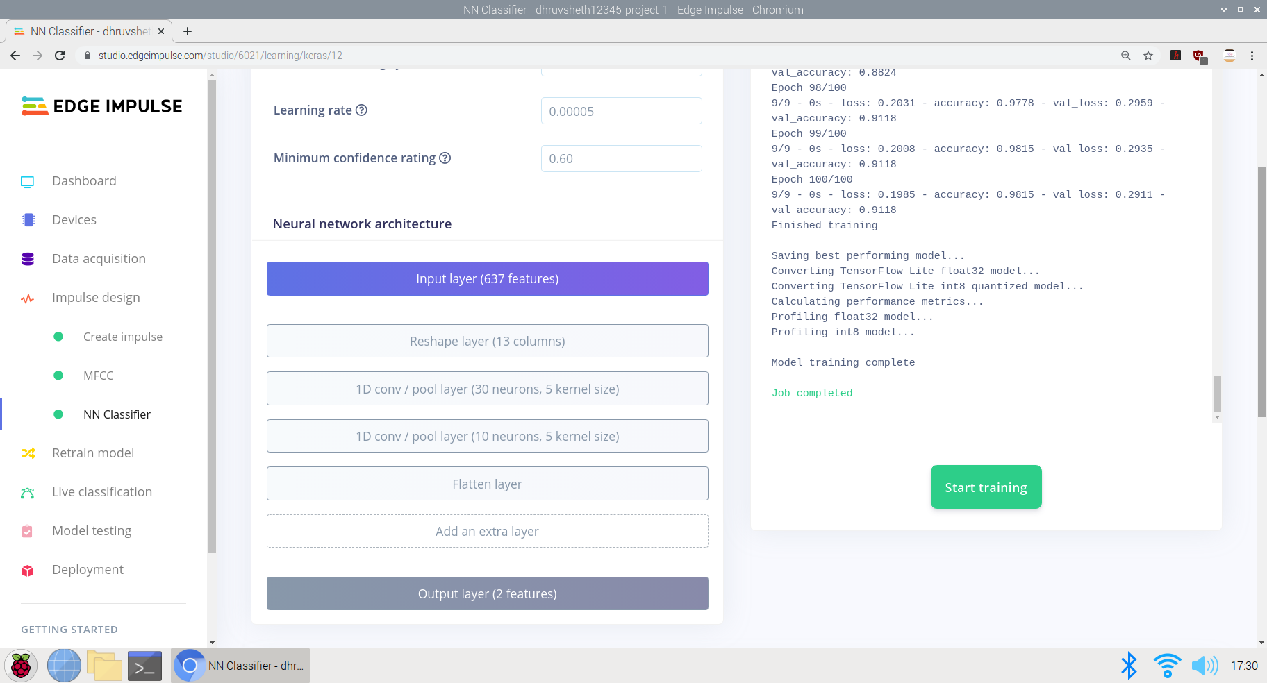
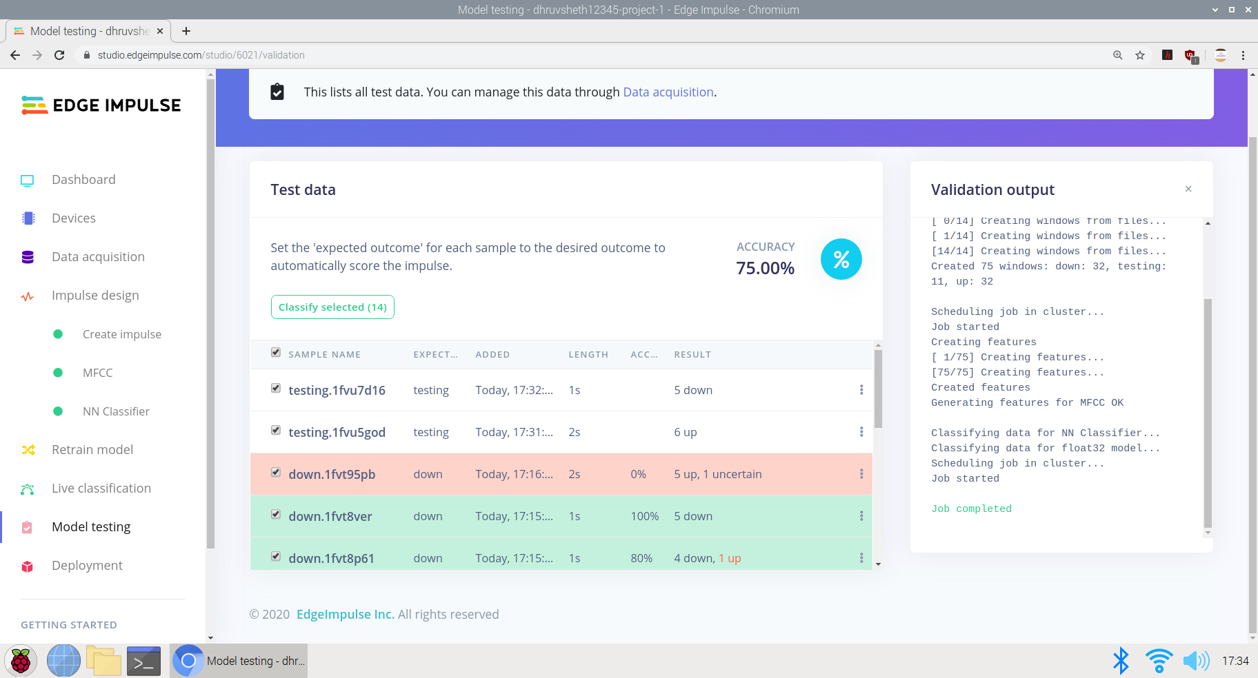
Le modèle s'est assez bien comporté avec une précision moyenne de 91,2 % et une perte de 0,29. Le modèle a été entraîné sur 100 cycles d'entraînement (époques). La matrice de confusion semble assez claire et précise avec la plupart des données restantes correspondant à leurs classes étiquetées respectives.
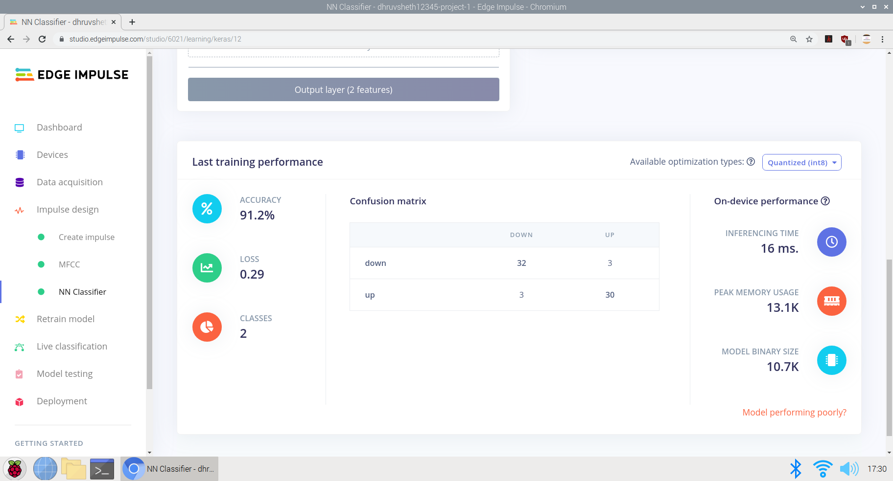
Une fois le modèle formé, j'ai testé le modèle avec des données de test et des données en direct et le modèle a obtenu une précision de 75 % sur la base de données de test de 24 secondes

Enfin, une fois que le modèle a été formé et a obtenu une précision décente avec la logique, j'ai déployé le modèle en tant que bibliothèque Arduino et je l'ai déployé sur le sens Arduino 33 BLE.
Une fois le script prêt, j'ai commencé à le modifier sur Arduino Web Editor pour faciliter la personnalisation et la sortie du script final qui pourrait être déployé sur Arduino 33 BLE Sense est la suivante :
Vous pouvez voir le fichier main.ino sur la plate-forme Arduino Web Editor ici :
Main-script.ino - Éditeur Web Arduino
Main-script.ino - Github
Déploiement sur Arduino 33 BLE Sense
Au moment d'écrire ces lignes, la seule carte Arduino avec un microphone intégré est l'Arduino Nano 33 BLE Sense, c'est donc ce que nous utiliserons pour cette section. Si vous utilisez une autre carte Arduino et attachez votre propre microphone, vous devrez implémenter
Au moment d'écrire ces lignes, la seule carte Arduino avec un microphone intégré est l'Arduino Nano 33 BLE Sense, c'est donc ce que nous utiliserons pour cette section.
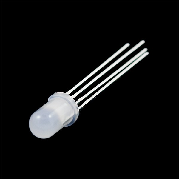
L'Arduino Nano 33 BLE Sense dispose également d'une LED intégrée, que nous utilisons pour indiquer qu'un mot a été reconnu et contrôler également le servo pour exécuter la fonction
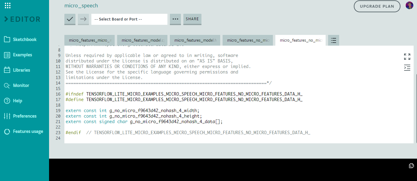
Voici un extrait du code des micro-fonctionnalités du modèle
La logique fonctionne comme suit pour la réponse à la commande :
// Si nous entendons une commande, allumez la LED appropriée et allumez le servo approprié
if (found_command[0] =='up') {
last_command_time =current_time;
digitalWrite(LEDG, LOW); // Vert pour le haut, allumage de la LED par la commande LOW
servo_7.write(0); // Rotation du servo à 0 degrés pour cliquer sur le bouton de l'ascenseur lorsque dit "up"
delay (100);
digitalWrite(LEDG, HIGH); // Eteindre la LED après avoir clignoté la commande
servo_7.write(180); // servo retournant à sa position d'origine c'est à dire 180degrés
}
// Si nous entendons une commande, allumez la LED appropriée et allumez le servo approprié
if (found_command[0] =='down') {
last_command_time =current_time;
digitalWrite(LEDG, LOW); // Vert pour le haut, allumage de la LED par la commande LOW
servo_7.write(0); // Rotation du servo à 0 degrés pour cliquer sur le bouton de l'ascenseur lorsqu'il dit "down"
delay (100);
digitalWrite(LEDG, HIGH); // Eteindre la LED après avoir clignoté la commande
servo_7.write(180); // servo retournant à sa position d'origine c'est-à-dire 180 degrés
}
La réponse de la deuxième commande est la même que ci-dessus, mais tourne le servo lorsque la commande "vers le bas" est entendue.
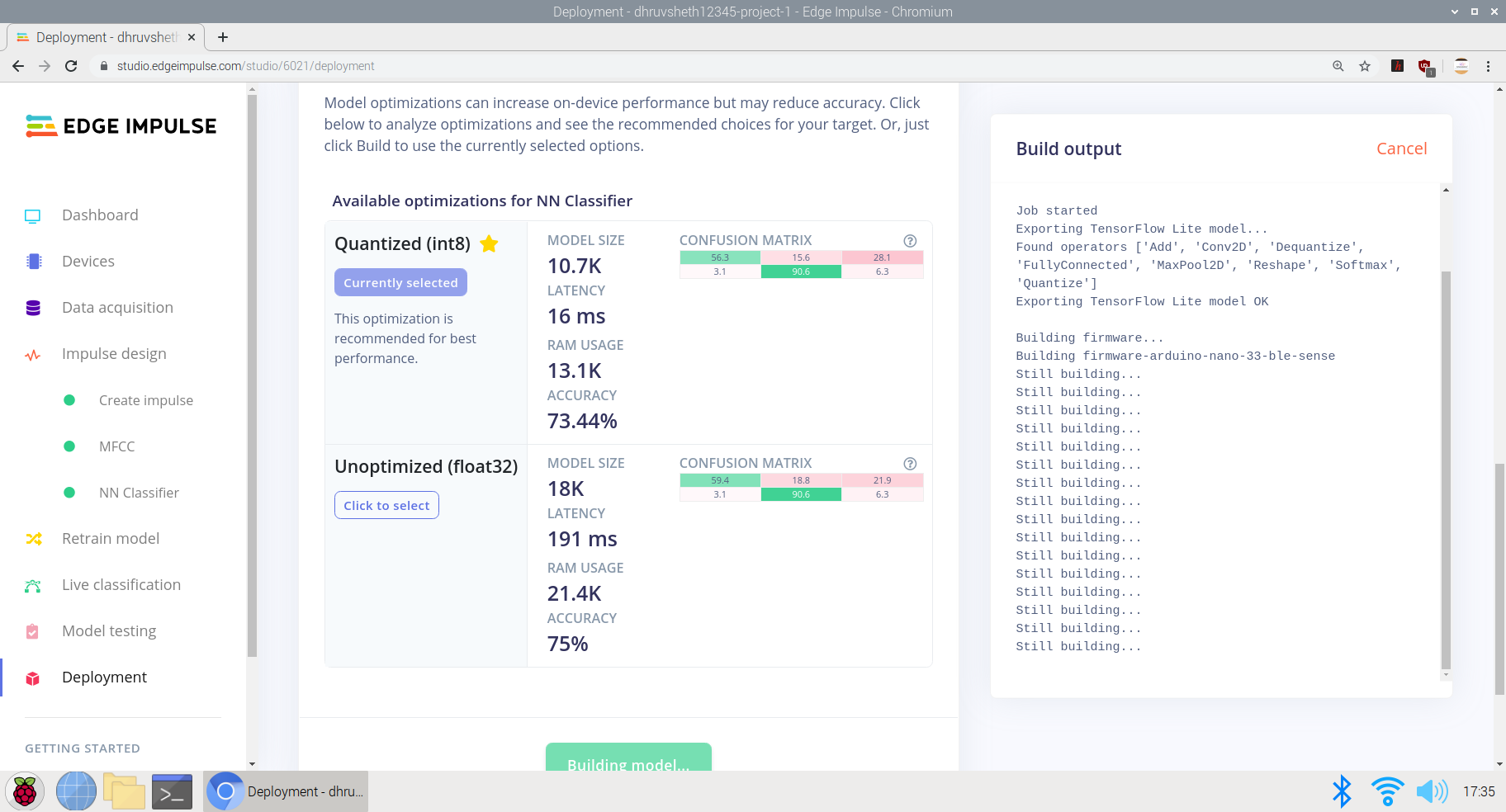
Après l'entraînement des données, nous obtenons une sortie d'ensemble de données tflite entraîné comme suit :
Ici, nous utilisons le microphone intégré sur l'Arduino Nano 33 BLE Sense et le modèle utilise en moyenne ~ 24-28 Ko de la mémoire flash de 256 Ko sur la carte Arduino Nano. Ce modèle est relativement léger par rapport au modèle de reconnaissance d'image et peut traiter les informations à un rythme beaucoup plus élevé.
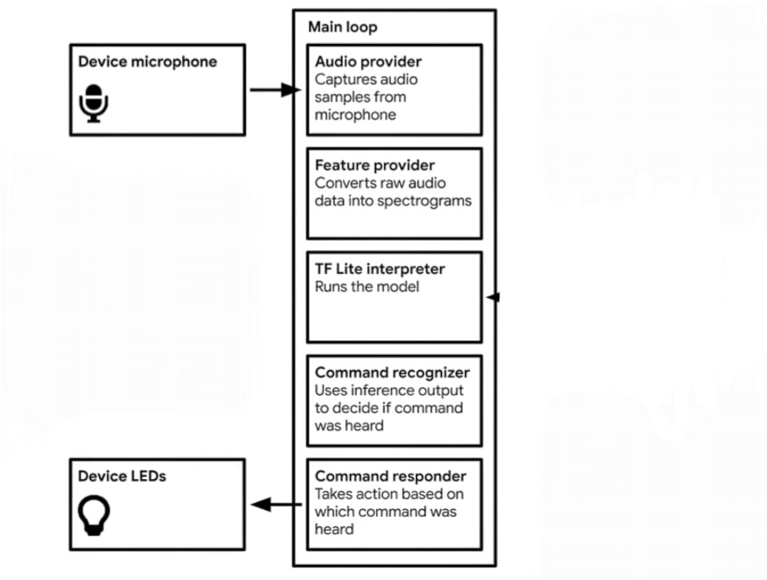
La logique du modèle de reconnaissance vocale est la suivante :
Les données sont capturéesCapture des échantillons audio à partir du microphoneConvertit les données audio brutes en spectrogrammesTflite Interpreter exécute le modèleUtilise la sortie d'inférence pour décider si la commande a été entendueSi la commande de descente est entendue, le servo se déplace en appuyant sur la touche descente du panneau de commande de levage.Si la commande de montée est entendue, le servo se déplace en appuyant sur la touche montée du panneau de commande de levage.
Le ci-dessus se trouvent les données de la bibliothèque du modèle entraîné. Les principales fonctions sont incluses dans le fichier Tensorflow.
Schéma de circuit pour le projet :

L'Arduino Nano 33 BLE Sense utilise le microphone intégré pour collecter des données brutes. Étant donné que l'inférence sur Arduino prend du temps, j'ai ajouté un délai de 100 millisecondes pour traiter les données avec précision. Ainsi, entre deux échantillons d'enregistrement, une led bleue intégrée clignote indiquant la réponse à entendre/dite entre les deux clignotements de led.

Il s'agit d'une simulation de l'Arduino 33 BLE Sense qui démontre le clignotement de la LED entre deux intervalles d'entrée de microphone réussis
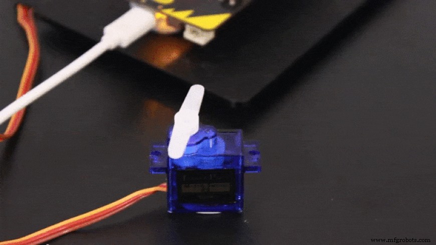
Sur la base de l'entrée de commande, le servo tourne en conséquence
Il existe maintenant d'autres alternatives à un système d'automatisation d'ascenseur sans contact, comme l'utilisation de capteurs à ultrasons ou de capteurs de gestes, mais les deux ont leurs propres défauts. J'ai donc décidé de créer le système d'automatisation d'ascenseur à commande vocale.
Défauts rencontrés dans les capteurs à ultrasons : Les capteurs à ultrasons sont très sensibles au mouvement. Si un objet se déplaçant dans le passage se trouve dans la plage des capteurs à ultrasons, ceux-ci sont activés. Les capteurs à ultrasons ne sont pas assez précis non plus, ils traitent parfois des informations erronées.
Défauts dans les capteurs contrôlés par les gestes : Ces capteurs sont plus précis que les capteurs à ultrasons, mais ils doivent être activés à une distance plus proche. Cela augmente le risque de contact entre les mains et le panneau de levage.
Cependant, le panneau d'ascenseur à commande vocale est plus précis que les deux solutions ci-dessus et peut être activé à une distance plus éloignée que le capteur à ultrasons et le capteur de geste.
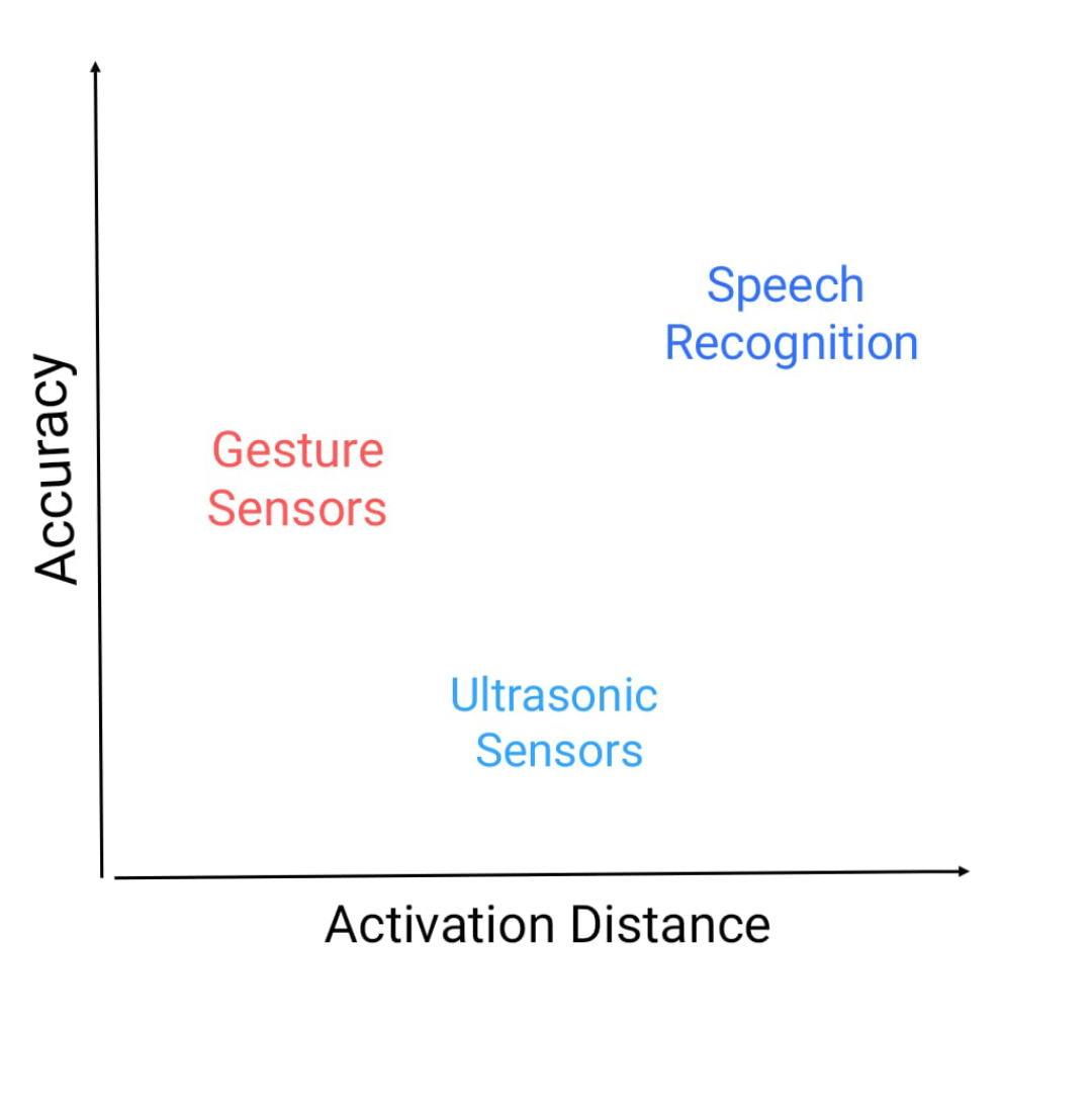
Voici un graphique de la précision en fonction de la distance d'activation et de la position de ces capteurs.
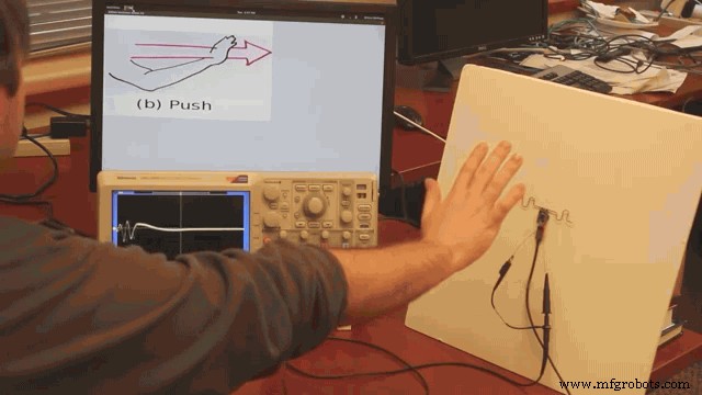
Cela montre la distance nécessaire pour activer le capteur de geste. Comme cette distance est perçue comme étant vraiment moindre, le taux de contamination est élevé
Ensuite, nous passons à la deuxième partie du sous-projet du projet principal
2ème projet :système d'interphone intelligent utilisant la reconnaissance faciale et TinyML :
Le CDC a mis à jour son site et publié un communiqué de presse indiquant que le contact indirect depuis une surface contaminée par le nouveau coronavirus, connu sous le nom de transmission fomite, est un moyen potentiel de contracter le nouveau coronavirus.
Des recherches ont montré que le nouveau coronavirus peut durer jusqu'à trois jours sur des surfaces en plastique et en métal et sur du carton pendant 24 heures. Cependant, il y a beaucoup de choses qui doivent arriver pour qu'une personne contracte le Covid-19 en touchant une surface contaminée.
Premièrement, une personne doit entrer en contact avec suffisamment de virus pour provoquer une infection. Par exemple, pour être infecté par le virus de la grippe, des millions de copies du virus doivent atteindre le visage d'une personne à partir d'une surface, mais seulement quelques milliers de copies sont nécessaires lorsque le virus pénètre directement dans les poumons, le New York Horaires rapports.
Si une personne touche une surface avec de grandes traces de virus, elle devra ramasser suffisamment de virus, puis se toucher les yeux, le nez ou la bouche - c'est pourquoi les experts en santé publique disent qu'il est si important d'éviter de toucher surfaces trop souvent et empêcher de toucher des objets contaminés ou des objets qui sont fréquemment touchés.
Le virus COVID-19 se propage à travers le monde. Même lorsque cela s'estompera enfin, les gens auront développé une sensibilité au fait de toucher des choses en public. Étant donné que la plupart des interphones sont conçus pour nécessiter une pression sur un bouton pour passer un appel, j'ai décidé qu'il fallait des solutions d'interphone sans contact qui n'exigent pas que les gens touchent quoi que ce soit.
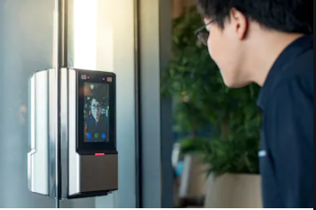
L'image ci-dessus montre un système d'interphone basé sur la reconnaissance faciale mis en œuvre.
Pour résoudre le problème des systèmes tactiles, il est nécessaire de réduire les lieux de contact et de toucher. Dans le système traditionnel d'interphones, ils consistent en des systèmes à interrupteurs, lorsqu'ils sont enfoncés, la cloche sonne. Pour réorganiser le système tactile qui augmente le risque de contamination des surfaces, j'ai décidé de construire un système de reconnaissance faciale sans contact déployé sur l'Arduino 33 BLE Sense, basé sur tinyML et Tensorflow Lite.
Dans ce système d'interphone intelligent, j'ai utilisé l'algorithme de détection de personne déployé sur Arduino 33 BLE Sense qui identifie les personnes et, en conséquence, sonne la cloche avec un affichage matriciel à LED indiquant "Personne".
Vers la mise en œuvre du système d'interphone intelligent :
Les logiciels suivants ont été utilisés dans la conception de ce modèle :
- TensorFlow lite
- Éditeur Web Arduino
Dans ce modèle de détection de personne, j'ai utilisé le modèle de détection de personne TensorFlow pré-entraîné adapté au projet. Ce modèle pré-entraîné se compose de trois classes dont la troisième classe avec un ensemble de données indéfini :
"inutilisé",
"personne",
"notperson"
In our model we have the Arducam Mini 2mp plus to carry out image intake and this image data with a decent rate of fps is sent to the Arduino Nano 33 BLE Sense for processing and and classification. Since the Microcontroller is capable of providing 256kb RAM, we change the image size of each image to a standard 96*96 for processing and classification. The Arduino Tensorflow Lite network consists of a deep learning framework as:
- Depthwise Conv_2D
- Conv_2D
- AVERAGE Pool_2D
- Flatten layer
This deep learning framework is used to train the Person detection model.
The following is the most important function defined while processing outputs on the Microcontroller via Arduino_detetction_responder.cpp
// Process the inference results.
 uint8_t person_score =output->data.uint8[kPersonIndex];
 uint8_t no_person_score =output->data.uint8[kNotAPersonIndex];
 RespondToDetection(error_reporter, person_score, no_person_score);
In the following function defining, the person_score , the no_person_score have been defined on the rate of classification of the data.
The Logic works in the Following way:
├── Autonomous Intercom System
├── Arducam Mini 2mp plus
│ ├── Visual data sent to Arduino
├── Arduino 33 BLE Sense
│ ├── if person-score> no_person_score
│ │ ├── Activate the buzzer
│ │ ├── Display "Person" on the LED Matrix
│ │ └── ...Repeat the loop
Adhering to the above logic, The arducam Mini 2mp plus continuously takes in visual data and sends this data to the Arduino 33 BLE Sense to process and classify the the data collected. Once the raw data is converted to processed data, it is then classified as per the data trained. If a person is detected, the Arduino sends a signal to the buzzer to activate and the MAX7219 to display "person". In this way, the logic of the system works.
Functioning and Working of Logic in Code:
The following are the Libraries included in themain.ino code for functioning of the model.
#include

#include "main_functions.h"

#include "detection_responder.h"
#include "image_provider.h"
#include "model_settings.h"
#include "person_detect_model_data.h"
#include "tensorflow/lite/micro/kernels/micro_ops.h"
#include "tensorflow/lite/micro/micro_error_reporter.h"
#include "tensorflow/lite/micro/micro_interpreter.h"
#include "tensorflow/lite/micro/micro_mutable_op_resolver.h"
#include "tensorflow/lite/schema/schema_generated.h"
#include "tensorflow/lite/version.h"
In the following code snippet, the loop is defined and performed. Since this is the main.ino code, it controls the core functioning of the model - used to run the libraries in the model.
void loop() {
 // Get image from provider.
 if (kTfLiteOk !=GetImage(error_reporter, kNumCols, kNumRows, kNumChannels,
 input->data.uint8)) {
 TF_LITE_REPORT_ERROR(error_reporter, "Image capture failed.");
 }

 // Run the model on this input and make sure it succeeds.
 if (kTfLiteOk !=interpreter->Invoke()) {
 TF_LITE_REPORT_ERROR(error_reporter, "Invoke failed.");
 }

 TfLiteTensor* output =interpreter->output(0);

 // Process the inference results.
 uint8_t person_score =output->data.uint8[kPersonIndex];
 uint8_t no_person_score =output->data.uint8[kNotAPersonIndex];
 RespondToDetection(error_reporter, person_score, no_person_score);
}
In the following code snippet, the necessary libraries required to inference the image to be captured is displayed. The images after captured are converted to a 96*96 standardised size which can be interpreted on the arduino board.
Here, the Arducam mini 2mp OV2640 library has been utilised.
This code has been provided in the arduino_image_provider.cpp snippet
#if defined(ARDUINO) &&!defined(ARDUINO_ARDUINO_NANO33BLE)
#define ARDUINO_EXCLUDE_CODE
#endif // defined(ARDUINO) &&!defined(ARDUINO_ARDUINO_NANO33BLE)

#ifndef ARDUINO_EXCLUDE_CODE

// Required by Arducam library
#include
#include
#include
// Arducam library
#include
// JPEGDecoder library
#include

// Checks that the Arducam library has been correctly configured
#if !(defined OV2640_MINI_2MP_PLUS)
#error Please select the hardware platform and camera module in the Arduino/libraries/ArduCAM/memorysaver.h
#endif

// The size of our temporary buffer for holding
// JPEG data received from the Arducam module
#define MAX_JPEG_BYTES 4096
// The pin connected to the Arducam Chip Select
#define CS 7

// Camera library instance
ArduCAM myCAM(OV2640, CS);
// Temporary buffer for holding JPEG data from camera
uint8_t jpeg_buffer[MAX_JPEG_BYTES] ={0};
// Length of the JPEG data currently in the buffer
uint32_t jpeg_length =0;

// Get the camera module ready
TfLiteStatus InitCamera(tflite::ErrorReporter* error_reporter) {
 TF_LITE_REPORT_ERROR(error_reporter, "Attempting to start Arducam");
 // Enable the Wire library
 Wire.begin();
 // Configure the CS pin
 pinMode(CS, OUTPUT);
 digitalWrite(CS, HIGH);
 // initialize SPI
 SPI.begin();
 // Reset the CPLD
 myCAM.write_reg(0x07, 0x80);
 delay(100);
 myCAM.write_reg(0x07, 0x00);
 delay(100);
 // Test whether we can communicate with Arducam via SPI
 myCAM.write_reg(ARDUCHIP_TEST1, 0x55);
 uint8_t test;
 test =myCAM.read_reg(ARDUCHIP_TEST1);
 if (test !=0x55) {
 TF_LITE_REPORT_ERROR(error_reporter, "Can't communicate with Arducam");
 delay(1000);
 return kTfLiteError;
 }
The following code is the Arduino_detection_responder.cpp code which controls the main output of the model. Here, we have taken into consideration, the classification score as defined in the main.ino code and according to the confidence of person score, I am providing outputs.
// Switch on the green LED when a person is detected,
 // the red when no person is detected
 if (person_score> no_person_score) {
 digitalWrite(LEDG, LOW); // if a person is detected at the door, the buzzer switches on
 digitalWrite(LEDR, HIGH); // the led matrix in the house displays "person"
 digitalWrite(5, LOW);
 myDisplay.setTextAlignment(PA_CENTER);
 myDisplay.print("Person");
 delay(100);
 } else {
 digitalWrite(LEDG, HIGH);
 digitalWrite(LEDR, LOW);
 }

 TF_LITE_REPORT_ERROR(error_reporter, "Person score:%d No person score:%d",
 person_score, no_person_score);
}

#endif // ARDUINO_EXCLUDE_CODE
Working of the Firmware:

This is the complete setup of the firmware designed on Fritzing.
This simulation shows the capture of data by the Arducam and similarly classification of this data by Arduino 33 BLE Sense
This model comprises of the following firmware used:
- Arduino 33 BLE sense - Used to process the data gathered, classifies the data processes, sends the command according to the logic fed.
- Buzzer - For Alerting when a person is at the door.
- Arducam Mini 2mp plus - Continuous Raw data image accumulation from source.
- Adafruit lithium ion charger - Used to deliver charge through the lithium battery
- Lithium ion Battery - power source
- MAX7219 4 in 1 display - Used for displaying "person" on the display screen.
Additional Features: Using the existing intercom system, it is possible to add a servo to push the button to view the person who is standing at the door as shown in the image:
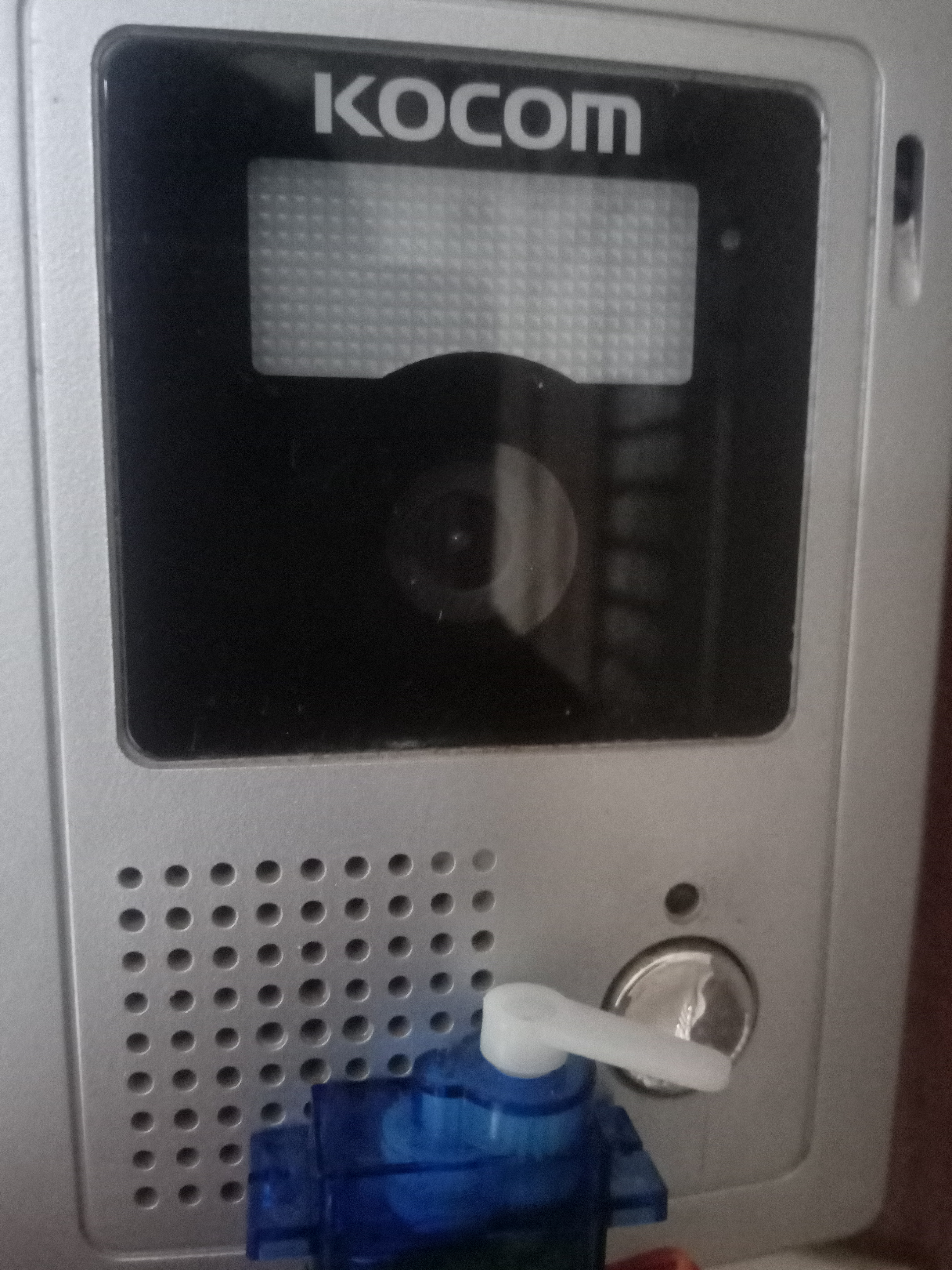

This can be an additional setup in intercom system to switch on video when a person is detected. However, this additional system has to be deployed on the Existing Intercom system.
Additional code added to the existing code:
// Switch on the green LED when a person is detected,
 // the red when no person is detected
 if (person_score> no_person_score) {
 digitalWrite(LEDG, LOW); // if a person is detected at the door, the buzzer switches on
 digitalWrite(LEDR, HIGH); // the led matrix in the house displays "person"
 digitalWrite(5, LOW);
 myDisplay.setTextAlignment(PA_CENTER);
 myDisplay.print("Person");
 servo_8.write(0); // this switches on the intercom by rotating servo
 delay(500);
 servo_8.write(180); // this switches off the intercom by rotating servo
 delay(100);
 } else {
 digitalWrite(LEDG, HIGH);
 digitalWrite(LEDR, LOW);
I have added an additional function which rotates the servo to switch on the existing intercom and then switches back to its original place.
3rd Project:Autonomous IoT based person temperature sensing automation:
The temperature sensor for Arduino is a fundamental element when we want to measure the temperature of a process or of the human body.
The temperature sensor with Arduino must be in contact or close to receive and measure the heat level. That's how thermometers work.
These devices are extremely used to measure the body temperature of sick people, as the temperature is one of the first factors that change in the human body, when there is an abnormality or disease.
One of the diseases that alter the temperature of the human body is COVID 19. Therefore, we present the main symptoms:
- Cough
- Tiredness
- Difficulty breathing (Severe cases)
- Fever
Fever is a symptom whose main characteristic is an increase in body temperature. In this disease, we need to constantly monitor these symptoms.
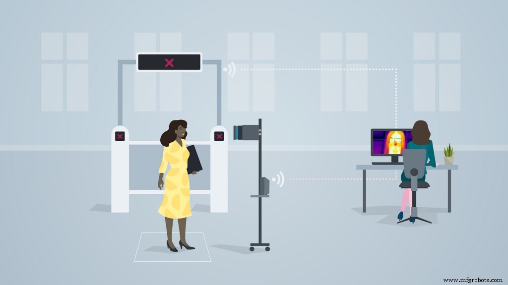
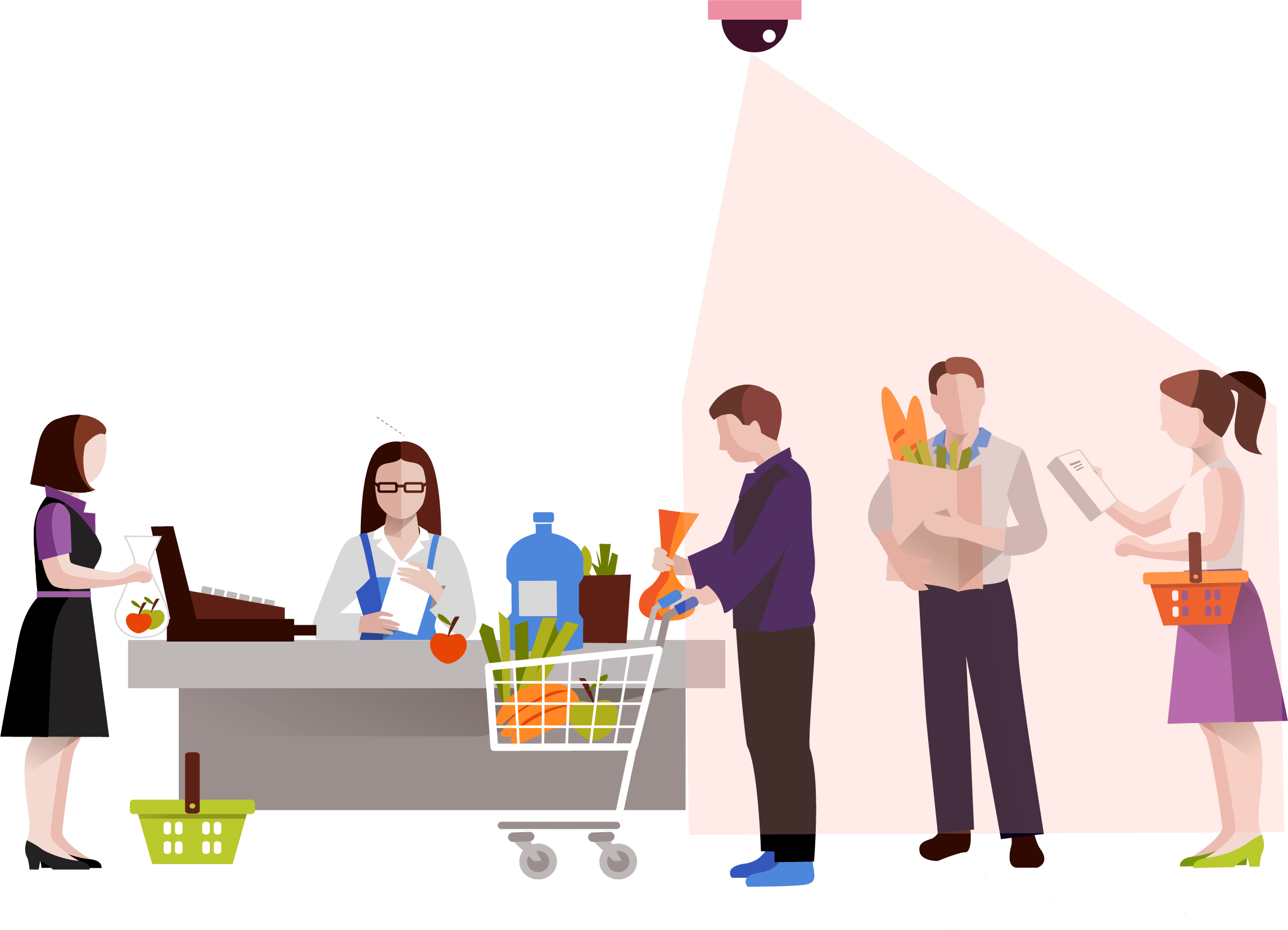
The retail market has been hit with a great impact due to the pandemic. After the malls and supermarkets have re-begun, it is necessary to ensure safety of all the customers who have entered the premises. For this purpose, manual temperature checking techniques have been set up. This increases the labour and also a risk of contact between the person checking the temperature and the person whose temperature is being check. This is demonstrated as follows:
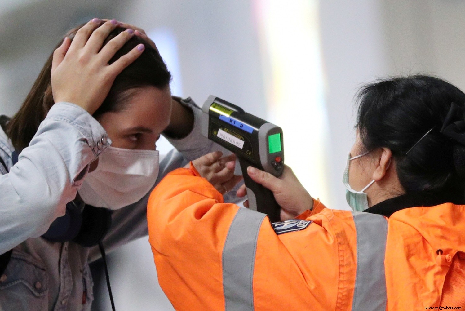
This image shows the close contact or less social distance maintained between the two persons.
There is a second flaw which is faced in manual temperature checking system:
For the temperatures which have been checked, the data of these recordings is not stored or not synchronised with an external device for monitoring the temperatures measured.
Taking in all these cons into consideration, I've come up with an Arduino based IoT solution deployed on the Arduino MKR WiFi 1010. The temperatures are measured using the Adafruit AMG8833 temperature module. Whenever a person is detected on the gate, the ultrasonic sensors, send the information to the Arduino MKR WiFi 1010 to give a command to the AMG 8833 module to take in temperature data. The module captures the data accurately and the data is projected on an IoT dashboard in real time. If an abnormal temperature reading of a person is detected, an alarm is set on so that the mall security and staff can immediately investigate upon the matter. The data collected is each given a timestamp and can be viewed on the ThingSpeak dashboard the temperature recording vs Time graph for each data.
Similarly, it can be also traced on which days and which time range, does the supermarket or the mall show abnormal temperature readings and more security measures can be implemented accordingly.
The below image shows wherethe setup can be embedded(The area where the setup can be installed)
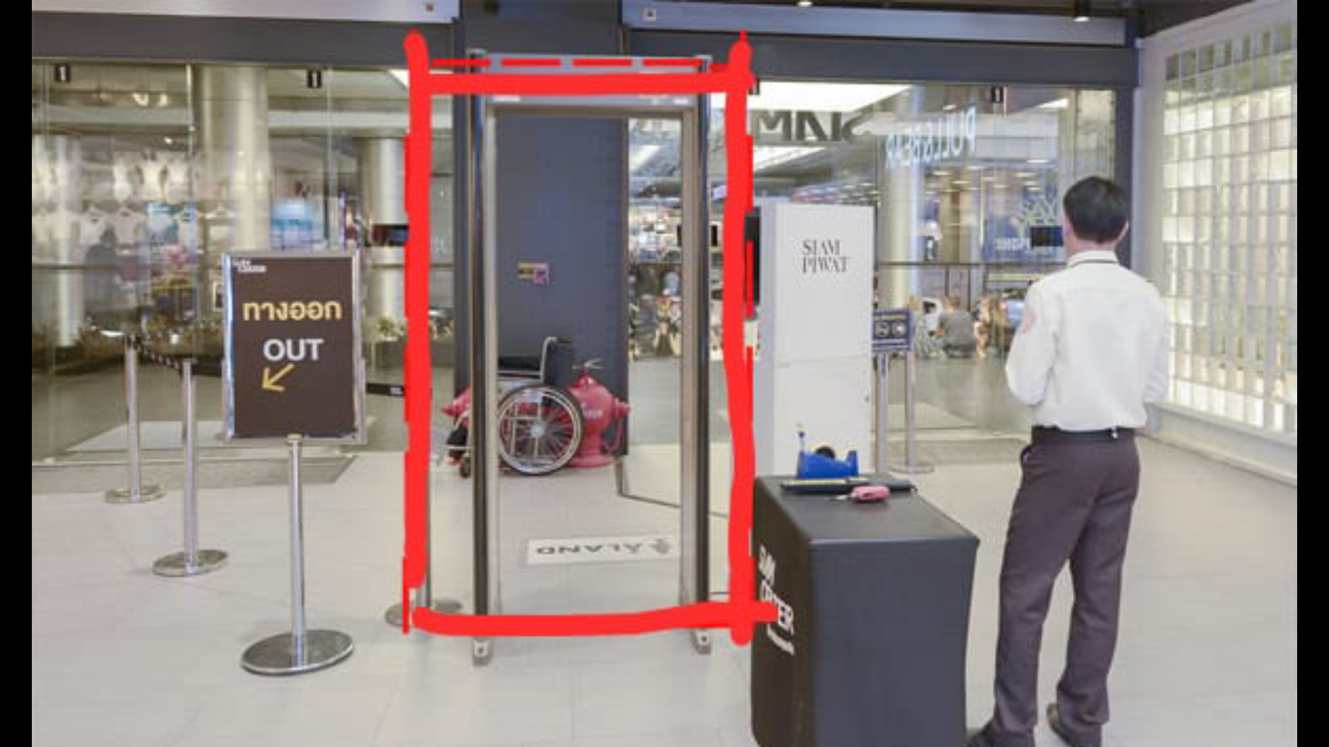
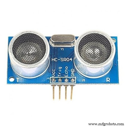
On the entry checking gate, HC-SR04 Ultrasonic Sensors can be installed which detects the entry of a person and sends the command to the Arduino MKR WiFi 1010 if the person is detected in a 20cm range. The Arduino microcontroller passes on the same command to the AMG 8833 temperature module to read the temperature of the person. This complete process takes time from the Ultrasonic Sensor detecting the person, to sending the command to the temperature module to detect the temperature. Hence, in order to sync with the delay, the temperature module is attached a bit far way from the Ultrasonic sensor.
Whenever a person walks in, the gate is opened ( Here, in the prototype, we are using the servo to function as a gate, but in further implementation of the project, the servo will be replaced by a heavy duty gate motor and controlled via motor driver, wherein the Arduino will be sending commands ). The temperature reading of the person is taken and this reading is sent to the thingspeak IoT dashboard in real time via the Arduino WiFi 1010. For this, an active wifi connection is required in the mall premises which is usually available in most of the cases. According to Research, the body temperature of a person with fever is approximately 38.1C which is 104F. Hence, if the Temperature module detects a temperature above this threshold, the servo turns 180Degrees and the Buzzer goes on to alarm people about the Person. Similarly, security and other mall staff can reach the area in time to control the situation when such a case happens.
The Logic works in the Following way:
├── PersonTemperature Detection MKR WiFi 1010
├── HC-Sr04 Ultrasonic sensor
│ ├── Person Detection
│ │ ├── If( Person distance =20) ,send command
├── Arduino
│ ├── if Ultrasonic sensor Sends a command;
│ │ ├── Open the gate - Servo(0)
│ │ ├── Activate the AMG8833 to take readings
│ │ ├── Send the Readings to ThingSpeak Dashboard
│ │ | ├── If Temperature> 38.1C
│ │ │ | ├── Close the gate - servo(180)
│ │ │ │ ├── Activate the Buzzer
│ │ └── ...Repeat the loop
In this way, the complete Logic of the Temperature Monitor Functions.
The circuit Diagram for the Temperature Model is given as follows:
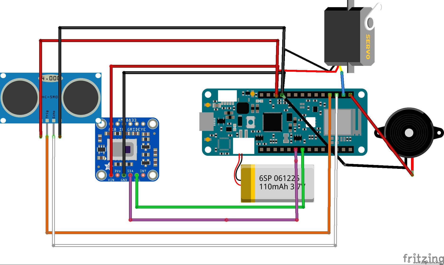
This is the complete Firmware and setup used in the project
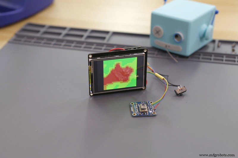
This simulation shows the data type captured by the AMG 8833 Thermal Cam and this data is sent to the Arduino MKR WiFi 1010 to transfer commands
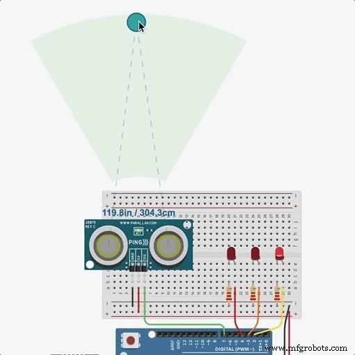
This simulation shows the distance captured by ultrasonic Sensor and this command is sent to the Arduino MKR WiFi to activate the AMG 8833 thermal sensor
Instead of a servo based door opening system, I will be implementing a command system using motor driver to automate door sliding opening system as follows:
Setting up the IoT Dashboard:
Using Thingsepak IoT Dashboard Setup:
ThingSpeak™ is an IoT analytics service that allows you to aggregate, visualize, and analyze live data streams in the cloud. ThingSpeak provides instant visualizations of data posted by your devices to ThingSpeak. With the ability to execute MATLAB® code in ThingSpeak, you can perform online analysis and process data as it comes in. ThingSpeak is often used for prototyping and proof-of-concept IoT systems that require analytics.
Since, ThingSpeak was easy to setup and use, I preffered to go with that dashboard. This interface allows the user to share the dashboard the security or staff department in the mall so that they can continuously monitor the people visiting the mall, and similarly impose restrictions at certain times when they feel the temperature risk is higher.
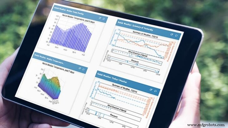
The above image represents the versatility of the thingspeak dashboard and the creative visualisations potrayed.
Logic used in the ThingSpeak IoT data collection process
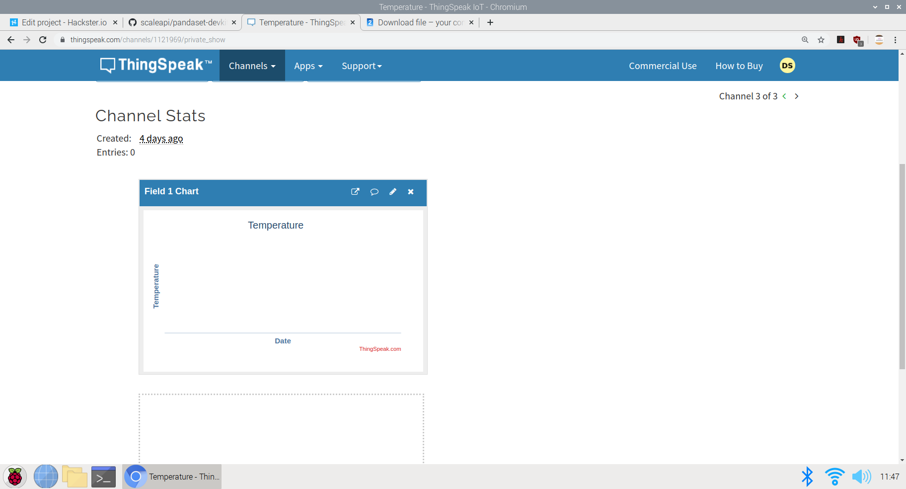
This image shows the creation of visualisations in different channels. Here, I've created a Temperature vs Time Graph in the visualisation section. The data collected by the AMG8833 sensor will be each allocated a timestamp and will be plotted on the graph to see the time for which each data is captured.
The data collected can be viewed in real time on the Public Dashboard here; ThingSpeak Temperature Dashboard
Similarly, this plot can be integrated cumulatively to a single Dashboard made open to the visitors of the mall to view the temperature data before entering the mall. If the visitors find an abnormal temperature reading at a particular day, they can prefer not to go to the supermarket or mall at that day to be safe,
The visualisation Integration data chart:
This chart can be embedded at a single dashboard with the readings of the charts of other malls and supermarkets in the particular area and hence, a unique visitor can check which mall is performing better than other mall in terms of safety and can prefer going to the mall where safety guidelines are followed and the people entering are not diagnosed with fever. This can help the Government help establish safety and trust within the people along with the re-opening of malls and retail sectors
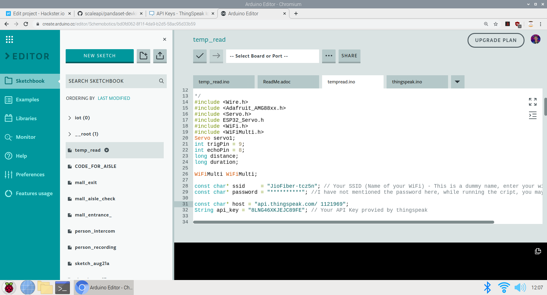
The code of the following project can be either viewed in Github or in the Arduino Web editor here; Temperature-Model-code
The logic in the code goes as follows:
#include
#include
#include
#include ESP32_Servo.h
#include
#include
Servo servo1;
int trigPin =9;
int echoPin =8;
long distance;
long duration;

WiFiMulti WiFiMulti;

const char* ssid ="JioFiber-tcz5n"; // Your SSID (Name of your WiFi) - This is a dummy name, enter your wifi ssid here
const char* password ="**********"; //I have not mentioned the password here, while running the cript, you may mention your pwd

const char* host ="api.thingspeak.com/1121969";
String api_key ="8LNG46XKJEJC89FE"; // Your API Key provied by thingspeak


Adafruit_AMG88xx amg;
Here, I have defined some of the Libraries and Firmware along with the required setup for the WiFi host and the API-Key for the temperature dashboard on thingspeak
Here's an image of the Code in progress:
The next part of the code is Setting up the required components before the actual loop begins:
These are the prerequisites before looping the actual code. I have defined the Servo pin and the Ultrasonic sensors while also begun the testing of the AMG 8833 to see if it can read data or if its connected
void setup()
{
 Serial.begin(9600);
servo1.attach(7);
 pinMode(trigPin, OUTPUT);
 pinMode(echoPin, INPUT);// put your setup code here, to run once:
}


{
 Connect_to_Wifi();
 Serial.println(F("AMG88xx test"));

 bool status;

 // default settings
 status =amg.begin();
 if (!status) {
 Serial.println("Could not find a valid AMG88xx sensor, check wiring!");
 while (1);
 }

 Serial.println("-- Thermistor Test --");

 Serial.println();

 delay(100); // let sensor boot up
}
The next part is the Void Loop where the complete function is carried out. Here, Initially I have set the gate to open to allow the entry of each person. The AMG 8833 performs data collection and reads the temperature of the people coming inside. If the temperature is higher than the expected threshold, the gate is closed and an alarm(buzzer) is set on to alert people and not allow the entry of the person
void loop()
ultra();
servo1.write(0);
if(distance <=20){
Serial.print("Thermistor Temperature =");
Serial.print(amg.readThermistor());
Serial.println(" *C");
Serial.println();
// call function to send data to Thingspeak
Send_Data();
//delay
delay(50);
if(amg.readThermistor()> 38.1) // if a person with fever is detetcted, he is not allowed to enter
// a person with fever has an avg body temperature of 38.1degree celsius
servo1.write(180);
digitalWrite(6, HIGH); //Turns on the buzzer to alarm people
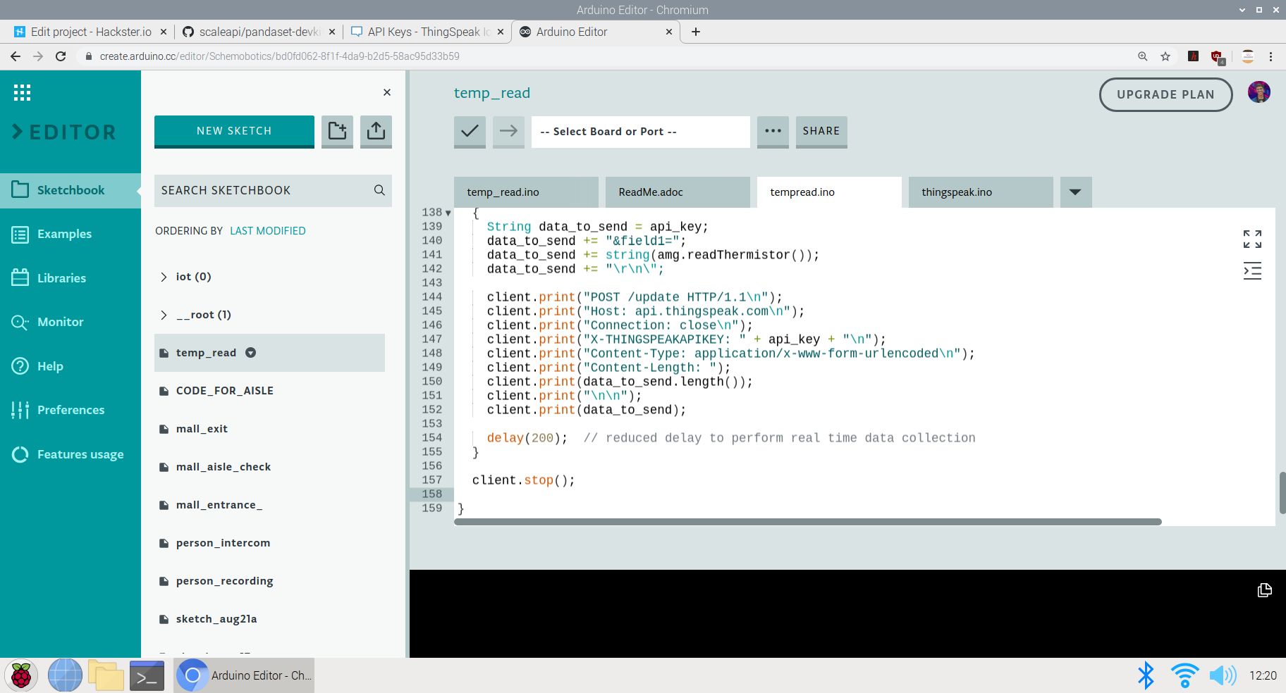
} The last part is sending the data to the ThingSpeak Dashboard:
Here, since I have only one field in the channel, all the data will be sent to that field. The captured, amg.readThermistor() data is sent to the dashboard.
void Send_Data()
{

 Serial.println("Prepare to send data");

 // Use WiFiClient class to create TCP connections
 WiFiClient client;

 const int httpPort =80;

 if (!client.connect(host, httpPort)) {
 Serial.println("connection failed");
 return;
 }
 else
 {
 String data_to_send =api_key;
 data_to_send +="&field1=";
 data_to_send +=string(amg.readThermistor());
 data_to_send +="\r\n\";

 client.print("POST /update HTTP/1.1\n");
 client.print("Host:api.thingspeak.com\n");
 client.print("Connection:close\n");
 client.print("X-THINGSPEAKAPIKEY:" + api_key + "\n");
 client.print("Content-Type:application/x-www-form-urlencoded\n");
 client.print("Content-Length:");
 client.print(data_to_send.length());
 client.print("\n\n");
 client.print(data_to_send);

 delay(200); // reduced delay to perform real time data collection
 }

 client.stop();

} 
This ends the code section of the project and we move on to explanation of the use and GO TO MARKET part of the project
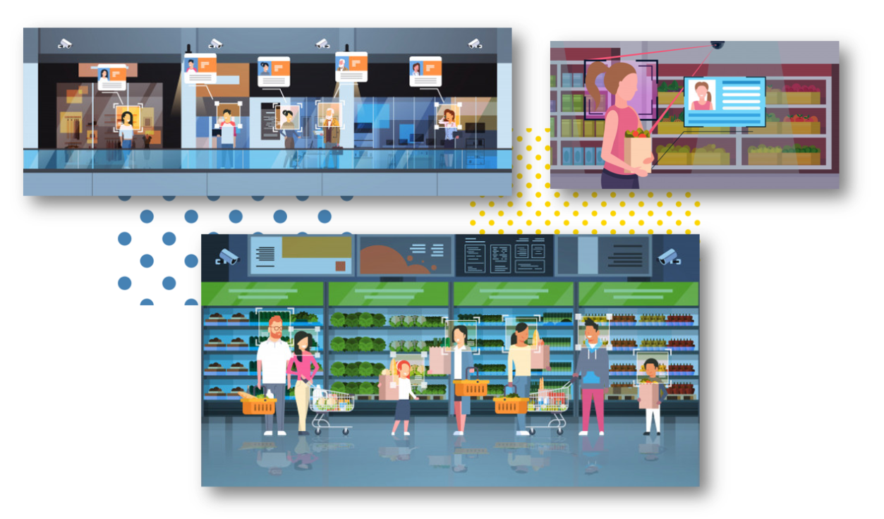
The above image shows the implementation of the methodology and model in supermarkets and malls.
GO TO MARKET &PRACTICALITY:
- Malls and Supermarkets can use this to identify Abnormal Temperature data and this data can be observed even for a certain day at a certain point of time.
- Implement Strategies using this data to ensure Safety and Compliance.
- Decrease Labour and automate Temperature Monitoring Process
- Offer Dashboard to the visitors to monitor if the mall is safe and and accordingly visit the mall at the safest point of time.
- This product can be used to ensure the visitors that the mall is a safe place and hence, can increase the sales and visits following Government guidelines
- Companies offering IoT based solutions can invest in this product for mass production and distribution.
- The more the supermarkets using this product, the more the access to data to the government and more the choice to customers to select the preferable safest place in their locality.
- Comparatively affordable solution as compared to manual temperature monitoring as it decreases the labour cost + decreases the rate of infection when compared to manual monitoring where the person taking temperature has to be close to the visitor to capture the temperature.
4th Project:TinyML &IoT based queue monitoring and establishing system deployed on the Arduino 33 BLE Sense:
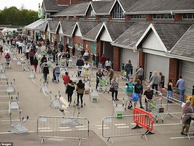
Just as the mall and the retail sector has opened, queue management in malls and supermarkets has become a big problem. Due to the pandemic, restricting only a certain amount of people to go inside the mall has has to be followed by the malls to ensure safety compliance. But this is done manually which increases labour work. Also the data for the number of people inside the mall at a given point of time is not available to the visitors of the mall. If this data would have been made available to the the visitors of the mall, it would increase the percentage of people visiting the mall.
Trying to run a shop or a service during the ongoing Corona crisis is certainly a challenge. Serving customers while keeping them and employees safe is tricky, but digital queuing can help a lot in this regard. The technologies behind virtual queues are not entirely new; the call for social distancing just highlights some of the many benefits they offer.
Most countries have introduced legal measures to combat the spread of COVID-19. To ensure customer satisfaction whilst adhering to the new regulations, one thing is for sure:long queues and crowded lobbies need to go. Digital queuing (also referred to as virtual or remote queuing) technology allows businesses to serve their customers in a timely manner while they stay out of harm’s way.
Generally speaking, you will likely find one or more of the following types of queue management solutions in a given retail environment:
- Structured queues: Lines form in a fixed, predetermined position. Examples are supermarket checkouts or airport security queues.
- Unstructured queues: Lines form naturally and spontaneously in varying locations and directions. Examples include taxi queues and waiting for consultants in specialist retail stores.
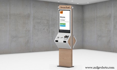
- Kiosk-based queues: Arriving customers enter basic information into a kiosk, allowing staff to respond accordingly. Kiosks are often used in banks, as well as medical and governmental facilities.
- Mobile queues: Rather than queuing up physically, customers use their smartphones. They do not have to wait in the store but rather can monitor the IoT Dashboard to see wait time at the store.
Long queues, whether they are structured or unstructured, often deter walk-in customers from entering the store. Additionally, they limit productivity and cause excess stress levels for customers and staff.
Does effective queue management directly affect the customer experience?
There is an interesting aspect about the experience of waiting in line:The waiting times we perceive often do not correspond with the actual times we spent in line. We may attribute a period of time falsely to be “longer” than normal or deem another period “shorter” despite it actually exceeding the average waiting time. For the most part, this has to do with how we can bridge the time waiting.
“Occupied time (walking to baggage claim) feels shorter than unoccupied time (standing at the carousel). Research on queuing has shown that, on average, people overestimate how long they’ve waited in a line by about 36 percent.”
The main reason that a customer is afraid to visit any supermarket is the problem of insufficient data. Visitors do not know the density of people inside the mall. The higher the number of people inside the mall, the higher is the risk of visiting the mall. Manually calculating the number of people who go enter and exit the mall and updating this data in real time is not possible. Also, a vistor does not know which day and at which time is is best suited to visit the mall. The visitor also does not know the wait time of each mall so that he can go with other supermarkets nearby if the wait time over there is less. As a result, all this leads to less conversion of people and accordingly less number of people visiting the mall. If the visitors have the access to population data, they have a sense of trust and leads to increase in sales of malls. Hence, I've come up with an Arduino Based TinyML and IoT solution to make this data available to the visitors and also increase the conversion of visitors in the mall by following the necessary safety guidelines. If the visitors have the access to population data, they have a sense of trust and leads to increase in sales of malls. Hence, I've come up with an Arduino Based TinyML and IoT solution to make this data available to the visitors and also increase the conversion of visitors in the mall by following the necess
This solution is based on computer vision and person detetction algorithm based on tensorflow framework.
It functions in the following way :
This solution is implemented on the gates of the mall or the supermarket. The Arducam mini 2mp keeps capturing image data and sends it to the Arduino 33 BLE Sense to process and classify this data. If a person is detected, The arduino increases the count of the stored data of number of people inside the mall by 1. Since a person is detected, the Servo motor rotates, opening the entrance to allow the person inside. For each person allowed inside, the data is sent to the ThingSpeak IoT dashboard which is open for the vistors to view.
When the person count increases the 50 threshold limit(This threshold can be altered depending upon the the supermarket size), the gate is closed and a wait time of 15min is set until the customers inside exit the store. The wait time is then displayed on the LED matrix display screen so that the customers in the queue can know the duration they have to wait for.
The people can also keep a track of the number of people inside the store. The number of people allowed to enter inside the store at a single time is 50 people.
The physical queuing unit of this product, helps in establishing queues while the IoT Dashboard helps in projecting the total count of the customers going in the store and total count of the customers going out of the store. Currently this is the dashboard data that will be displayed but I am working on a logic for displaying the waiting time required for the customer to get inside the mall. The logic for it is pretty simple, it depends on the number of people inside the mall. The total no of people entering the mall displayed on dashboard minus the total no of people exited the mall displayed on the dashboard. This will give us an outcome of the total no of people inside the store. The next operation would be the total no of people outside the store subtracted by the threshold (limit that the store can accommodate). If the outcome is a negative integer, the waiting time would be multiplication of the negative integer by the negative of the average time a person spends inside the store. If the outcome of the operation would be a positive integer, the wait time would be none.
Heading towards the implementation of the physical queuing system:
The following Softwares have been used in designing this model:
- TensorFlow lite
- ThingSpeak
- Arduino Web Editor
In this person detection model, I have used the Pre-trained TensorFlow Person detection model apt for the project. This pre-trained model consists of three classes out of which the third class is with undefined set of data:
"unused",
"person",
"notperson"
In our model we have the Arducam Mini 2mp plus to carry out image intake and this image data with a decent rate of fps is sent to the Arduino Nano 33 BLE Sense for processing and and classification. Since the Microcontroller is capable of providing 256kb RAM, we change the image size of each image to a standard 96*96 for processing and classification. The Arduino Tensorflow Lite network consists of a deep learning framework as:
- Depthwise Conv_2D
- Conv_2D
- AVERAGE Pool_2D
- Flatten layer
This deep learning framework is used to train the Person detection model.
The following is the most important function defined while processing outputs on the Microcontroller via Arduino_detetction_responder.cpp
// Process the inference results.
 uint8_t person_score =output->data.uint8[kPersonIndex];
 uint8_t no_person_score =output->data.uint8[kNotAPersonIndex];
 RespondToDetection(error_reporter, person_score, no_person_score);
In the following function defining, the person_score , the no_person_score have been defined on the rate of classification of the data.
using these defined functions, I will be using it to give certain outputs on the basis of confidence of the person-score and the no_person_score .
The detection responder logic of the code works in the following way:
├── Person Detection and responder - Entry
├── Arducam mini 2MP Plus
│ ├──Image and Video Data to Arduino
├── Arduino BLE 33 Sense
│ ├── processing and classification of the input data
│ │ ├── If person detected, open the gate - servo(180)
│ │ ├── If no person detected, close the gate - servo(0)
│ │ ├── Send the number of people entered count to to ThingSpeak Dashboard via ESP8266 -01
│ │ | ├── If people count has exceeded 50
│ │ │ | ├── Close the gate &wait for 15min to let the people inside move out
│ │ │ │ ├── Display wait time on a LED Matrix
│ │ └── ...Repeat the loop
├── Person Detection and responder - Exit
├── Arducam mini 2MP Plus
│ ├──Image and Video Data to Arduino
├── Arduino BLE 33 Sense
│ ├── processing and classification of the input data
│ │ ├── If person detected, open the gate - servo(180)
│ │ ├── If no person detected, close the gate - servo(0)
│ │ ├── Send the number of people entered count to to ThingSpeak Dashboard via ESP8266 -01
│ │ └── ...Repeat the loop
Adhering to the logic used in the model, the Arducam mini 2mp plus will continuously capture Image data and sends this data to the Arduino 33 BLE Sense to process and classify the data. The overall model size is 125KB. If a person has been detected, the Arduino sends the command to the servo to rotate to servo to 180degree. If a person is not detected, the servo is rotated to 0degree and the gate is closed. Each time a person is detected, the the count increments by 1. If the count exceeds the 50 threshold, no more person is allowed inside and a wait time of 15min is set.
The wait time is continuously displayed and updated on the LED Matrix dislplay.
This count is also displayed on the ThingSpeak IoT dashboard via the ESP8266 01
Through the Dashboard, an individual can easily view the number of people are inside at a given day at a given point of time.
At the exit gate, the same logic is set. If a person is detected, the gate is opened while if no person is detected, the gate is closed. Each time a person is detected, the count increases by 1. This count is displayed on the ThingSpeak IoT dashboard.
In this way one can monitor the number of people entering and the number of people exiting.
Since the two models for entry and exit are deployed on two different microcontrollers, calculating the average wait time based on data from different microcontroller is a bit hard, but this uses a simple logic function.
x =No of people who have entered
Y =No of people who have exited
X - Y =No of people who are inside the mall
Z =Threshold of the no of people who are allowed to be inside the mall
let Z-(X-Y) =count {this is the number of people (in negative) who have either crossed the threshold limit or are below the threshold limit
If "count" is negative, The wait time is equal to count*(the negative of the average time a person spends inside the mall)
if "count" is positive, the wait time is zero
In this way, the average queue time calculating algorithm is imposed.
Working of the Firmware:

This is the complete setup of the firmware designed on Fritzing.
This model comprises of the following firmware used:
- Arduino 33 BLE sense - Used to process the data gathered, classifies the data processes, sends the command according to the logic fed.
- MG959 / MG995 Servo - Heavy duty servo( An external power supply may be applied) - To open and close the gates as per microcontroller command.
- Arducam Mini 2mp plus - Continuous Raw data image accumulation from source.
- Adafruit lithium ion charger - Used to deliver charge through the lithium battery
- Lithium ion Battery - power source
- ESP8266 - 01 - Used for sending data to the ThingSpeak dashboard via WiFi network.
- MAX7219 4 in 1 display - Used for displaying the wait time on the display screen.
Functioning and Working of Logic in Code:
The following are the Libraries included in themain.ino code for functioning of the model.
#include

#include "main_functions.h"

#include "detection_responder.h"
#include "image_provider.h"
#include "model_settings.h"
#include "person_detect_model_data.h"
#include "tensorflow/lite/micro/kernels/micro_ops.h"
#include "tensorflow/lite/micro/micro_error_reporter.h"
#include "tensorflow/lite/micro/micro_interpreter.h"
#include "tensorflow/lite/micro/micro_mutable_op_resolver.h"
#include "tensorflow/lite/schema/schema_generated.h"
#include "tensorflow/lite/version.h"
In the following code snippet, the loop is defined and performed. Since this is the main.ino code, it controls the core functioning of the model - used to run the libraries in the model.
void loop() {
 // Get image from provider.
 if (kTfLiteOk !=GetImage(error_reporter, kNumCols, kNumRows, kNumChannels,
 input->data.uint8)) {
 TF_LITE_REPORT_ERROR(error_reporter, "Image capture failed.");
 }

 // Run the model on this input and make sure it succeeds.
 if (kTfLiteOk !=interpreter->Invoke()) {
 TF_LITE_REPORT_ERROR(error_reporter, "Invoke failed.");
 }

 TfLiteTensor* output =interpreter->output(0);

 // Process the inference results.
 uint8_t person_score =output->data.uint8[kPersonIndex];
 uint8_t no_person_score =output->data.uint8[kNotAPersonIndex];
 RespondToDetection(error_reporter, person_score, no_person_score);
}
In the following code snippet, the necessary libraries required to inference the image to be captured is displayed. The images after captured are converted to a 96*96 standardised size which can be interpreted on the arduino board.
Here, the Arducam mini 2mp OV2640 library has been utilised.
This code has been provided in the arduino_image_provider.cpp snippet
#if defined(ARDUINO) &&!defined(ARDUINO_ARDUINO_NANO33BLE)
#define ARDUINO_EXCLUDE_CODE
#endif // defined(ARDUINO) &&!defined(ARDUINO_ARDUINO_NANO33BLE)

#ifndef ARDUINO_EXCLUDE_CODE

// Required by Arducam library
#include
#include
#include
// Arducam library
#include
// JPEGDecoder library
#include

// Checks that the Arducam library has been correctly configured
#if !(defined OV2640_MINI_2MP_PLUS)
#error Please select the hardware platform and camera module in the Arduino/libraries/ArduCAM/memorysaver.h
#endif

// The size of our temporary buffer for holding
// JPEG data received from the Arducam module
#define MAX_JPEG_BYTES 4096
// The pin connected to the Arducam Chip Select
#define CS 7

// Camera library instance
ArduCAM myCAM(OV2640, CS);
// Temporary buffer for holding JPEG data from camera
uint8_t jpeg_buffer[MAX_JPEG_BYTES] ={0};
// Length of the JPEG data currently in the buffer
uint32_t jpeg_length =0;

// Get the camera module ready
TfLiteStatus InitCamera(tflite::ErrorReporter* error_reporter) {
 TF_LITE_REPORT_ERROR(error_reporter, "Attempting to start Arducam");
 // Enable the Wire library
 Wire.begin();
 // Configure the CS pin
 pinMode(CS, OUTPUT);
 digitalWrite(CS, HIGH);
 // initialize SPI
 SPI.begin();
 // Reset the CPLD
 myCAM.write_reg(0x07, 0x80);
 delay(100);
 myCAM.write_reg(0x07, 0x00);
 delay(100);
 // Test whether we can communicate with Arducam via SPI
 myCAM.write_reg(ARDUCHIP_TEST1, 0x55);
 uint8_t test;
 test =myCAM.read_reg(ARDUCHIP_TEST1);
 if (test !=0x55) {
 TF_LITE_REPORT_ERROR(error_reporter, "Can't communicate with Arducam");
 delay(1000);
 return kTfLiteError;
 }
The final part where in the complete model is controlled is the Arduino_detection_responder.cpp.
This is a small code snippet of the entire logic used. When the confidence score of a person is greater than the confidence score of no person, the gate is opened and it is assumed that the person is detected. For this purpose the servo is moved to 0Degree to open the gate. On the detection of a person, the count is incremented by 1 =initially which began at 0. This count indicates the number of people coming inside. The num value of the count is sent to the ThingSpeak IoT dashboard which represents the number of people entering. When the count reaches the value of 50; the gate is closed and a wait time of 15min is imposed on the queue. The gate is closed and wait time is imposed each time 50 people enter. For this a logic of multiples of 50 is set
// Switch on the green LED when a person is detected,
 // the red when no person is detected
 if (person_score> no_person_score) {
 digitalWrite(LEDG, LOW);
 digitalWrite(LEDR, HIGH);
 servo_8.write(0); // this servo moves to 0degrees in order to open the mall door when a person is detected to ensure no touch entry system
 count++

 } else {
 digitalWrite(LEDG, HIGH);
 digitalWrite(LEDR, LOW);
 servo_8.write(180); // this servo moves to 180degrees when no person is detected
 }

 TF_LITE_REPORT_ERROR(error_reporter, "Person score:%d No person score:%d",
 person_score, no_person_score);
}


// Now we have let in 50people inside the store, so we set a delay of 15min wait time for others waiting outside to let them in
// Displaying wait time on the screen every 1min

 if(count =y*50) // when people are detected in multiples of 50, we instruct it to start displaying wait time to other people to wait until 15 min
 myDisplay.setTextAlignment(PA_CENTER);
 myDisplay.print("Waiting 15min");
delay(60000); 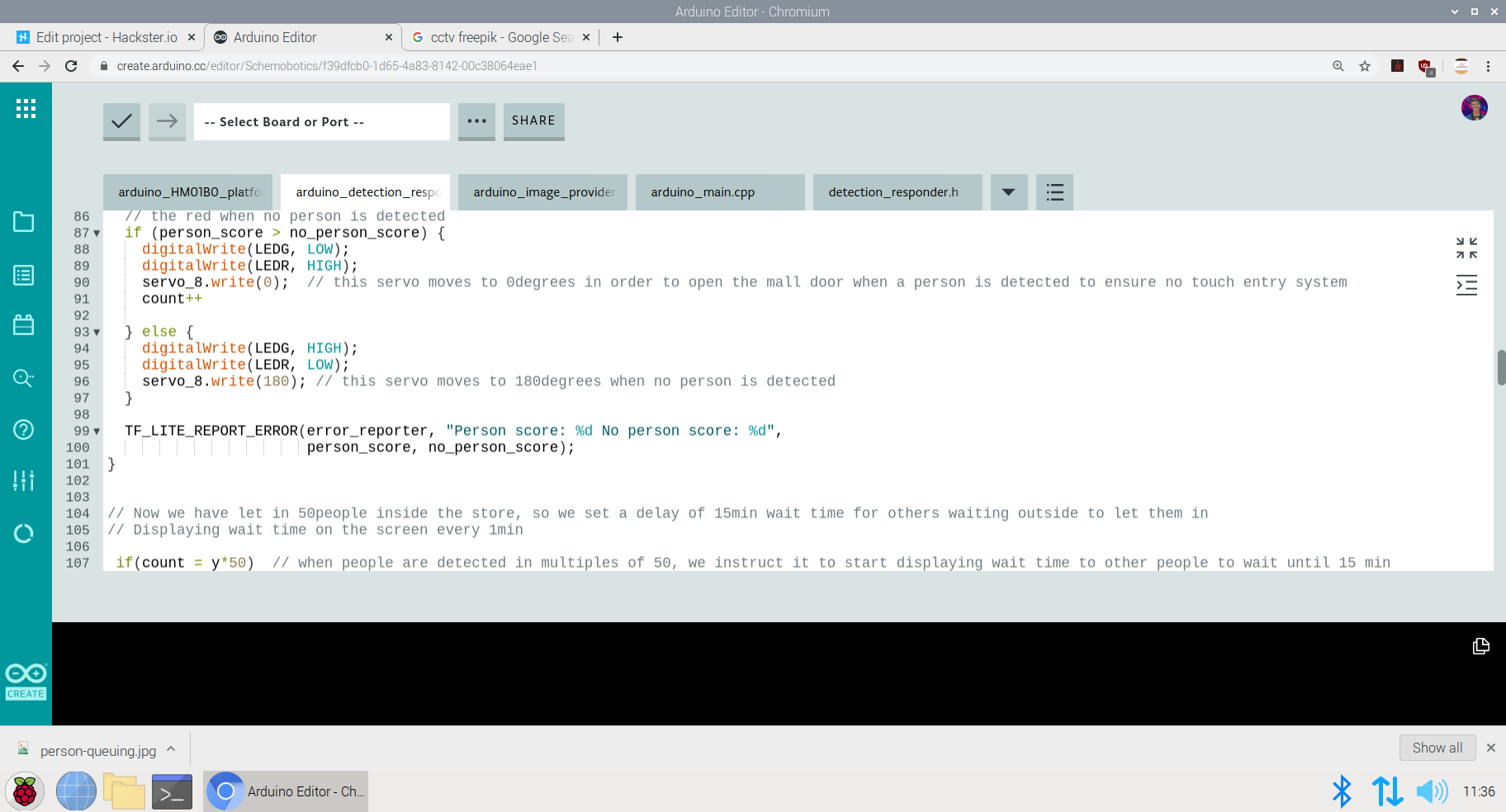
Setting up the ThingSpeak Dashboard:
Since the features in Thingspeak Dashboard are limited, I will not be implementing the Time prediction algorithm right now but I am working on the logic to communicate and write data from the Dashboard to microcontroller to perform the time calculation algorithm.
In the ThingSpeak Dashboard, I have added two fields; one for entry and the other one for exit.
The co-ordinates for the store or mall for which the queuing system is displayed, is also added in the form of a map.
The data displayed for the first field is gathered through the entry responding logic and the data displayed for the second field is gathered through the exit responding logic.
This is the snip of the two different logics used in the model.
The ThingSpeak Dashboard can be made available to the the staff of the store to check the number of people entering the store in real time and the number of people exiting the store in real time. This data can also be observed to see the analysis of the data at a given day at a a given time to check and impose further restrictions if required if the limit of people in the store exceeds the expected number of people at a given day
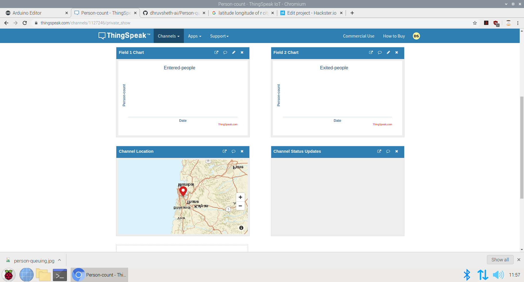
This Dashboard can be viewed here:IoT Dashboard
The following represents the field created for this purpose.
Now, a question might arise that for person detection model that this model can be replaced by ultrasonic or infrared sensors. Flaws in Ultrasonic Sensors or Infrared Based Sensors:These sensors are not exactly accurate and for the real time person count display, these sensors may provide wrong readings. Also, these sensors add as additional hardwares while in Go to Market Solutions, the person detection algorithm can be implemented in existing cameras and can reduce hardware cost. The data from these cameras could be sent to the Arduino BLE sense for central Classification and data processing.
GO TO MARKET &PRACTICALITY:
- Malls and Supermarkets can use this to identify The count of people entering and exiting the mall in real time.
- Implement Strategies using this data to ensure Safety and Compliance with efficient Queue management algorithms.
- Decrease Labour and automate Queue Management Process
- Offer Dashboard to the visitors to monitor the density of people inside the mall and accordingly visit the mall at the safest point of time.
- This product can be used to ensure the visitors that the mall is a safe place and hence, can increase the sales and visits following Government guidelines
- Companies offering Ai and IoT based solutions can invest for mass production and distribution.
- The more the supermarkets using this product, the more the access to data to the government and more the choice to customers to select the preferable safest place in their locality along with the the queue time required for each store can be monitored. This will lead to a wide range of options of supermarkets in the locality comparing the queue time and safety.
- Comparatively affordable solution as compared to manual queuing system and updating information manually to the Dashboard.
- Utilize real-time CCTV footage to impose Queue management in a mall/shop through person detection in terms of timely trends and spatial analysis of person density in the mall.
- Enable Stores to make better, data-driven decisions that ensure your safety and efficient Queues based on autonomous queuing system.
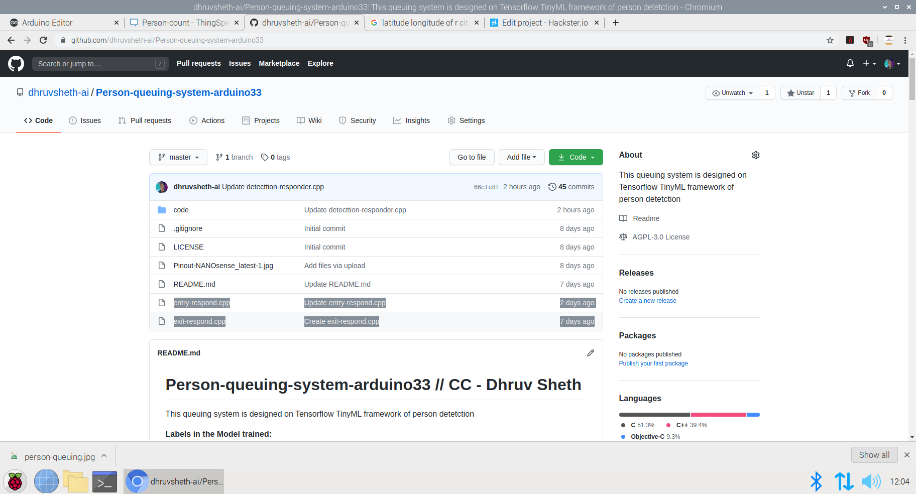
Github Code:Arduino Autonomous TinyML and IoT based queuing system.
Addition to the Existing Person Detection Algorithm- Mask Detection System:
Mask Detection Model based on TinyML :
Dr. Kierstin Kennedy, chief of hospital medicine at the University of Alabama at Birmingham, said, “Masks can protect against any infectious illness that may be spread by droplets. For example, the flu, pertussis (whooping cough), or pneumonia.”
Adding that wearing a cloth mask has benefits beyond slowing the spread of COVID-19, and that source control can reduce the transmission of many other easily spread respiratory infections — the kind that typically render people infectious even before they display symptoms, like influenza.
Until the threat of this pandemic has been neutralized, people should embrace the protection masks allow them to provide to those around them.
After all, it’s not necessarily about you — it’s about everyone you come in contact with.
It’s not at all uncommon to be an asymptomatic carrier of the new coronavirus — which means that even if you have no symptoms at all, you could potentially transmit the virus to someone who could then become gravely ill or even die.
Adhering to this, I decided to increase the necessity of wearing face-masks along with touch-free systems to increase safety in malls and supermarkets. Along with the person detection algorithm, I decided to make a custom face mask detection model which detects face masks and displays this data on the ThingSpeak IoT dashboard to increase awareness among mall staff as well as the visitors coming inside so that they are aware of the time trends when the most number of people are without masks. Through this there is a increases of sense of warning and awareness in people to wear masks. Accordingly, the store staff can keep a monitor on these trends and increase restrictions based on data driven statistics.
Deciding upon the Logic and Dataset of the Model:
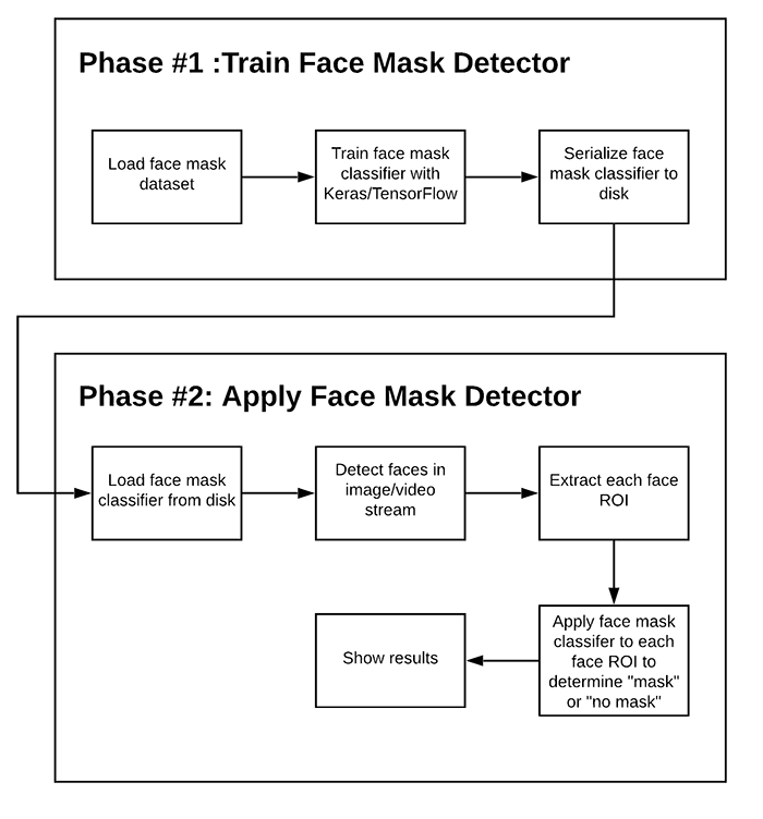
This is an overall Logic used in most of face mask detection algorithms. Since, we are deploying this model to an Arduino 33 BLE Sense, the deployment process of this model will vary.
There are two steps involved in constructing the model for Face Mask Detection.
- Training: Here we’ll focus on loading our face mask detection dataset from disk, training a model (using Keras/TensorFlow) on this dataset, and then serializing the face mask detector to disk
- Deployment: Once the face mask detector is trained, we can then move on to loading the mask detector, performing face detection, and then classifying each face as
maskorno_mask
Dataset used in training this model:
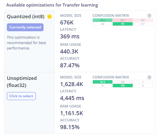
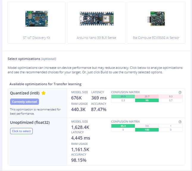
The dataset used in this process consists of 3500 images but to reduce the size of the model, and feed in accurate model images, I have used 813 images to increase accuracy of the model by decreasing bulk size. This model is an average 676K in size and utilizes nearly 440.3K Ram. Since this model is the optimized version of the original model, the accuracy of the model is 87.47% as compared to 98.15% in the non-optimized one.
The following Softwares have been used in designing this model:
- TensorFlow lite
- ThingSpeak
- Arduino Web Editor
Heading towards designing the model in EdgeImpulse Studio:
Powerful deep learning models (based on artificial neural networks) are now reaching microcontrollers. Over the past year great strides were made in making deep learning models smaller, faster and runnable on embedded hardware through projects like TensorFlow Lite for Microcontrollers, uTensor and Arm’s CMSIS-NN; but building a quality dataset, extracting the right features, training and deploying these models is can still be complicated.
Using Edge Impulse you can now quickly collect real-world sensor data, train ML models on this data in the cloud, and then deploy the model back to your Arduino device. From there you can integrate the model into your Arduino sketches with a single function call.
Step 1 - Acquisition of Data in the Edge Impulse Studio:
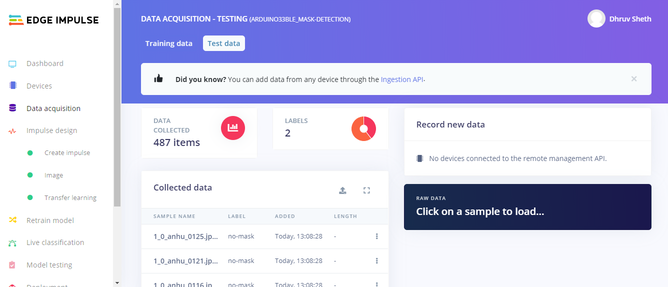
Using the dataset of 3500 images, I filtered these images to the best performing images and finally fed in 813 images totally in the Training Data and 487 images in the testing Data. I labelled these classes as mask and no_mask.
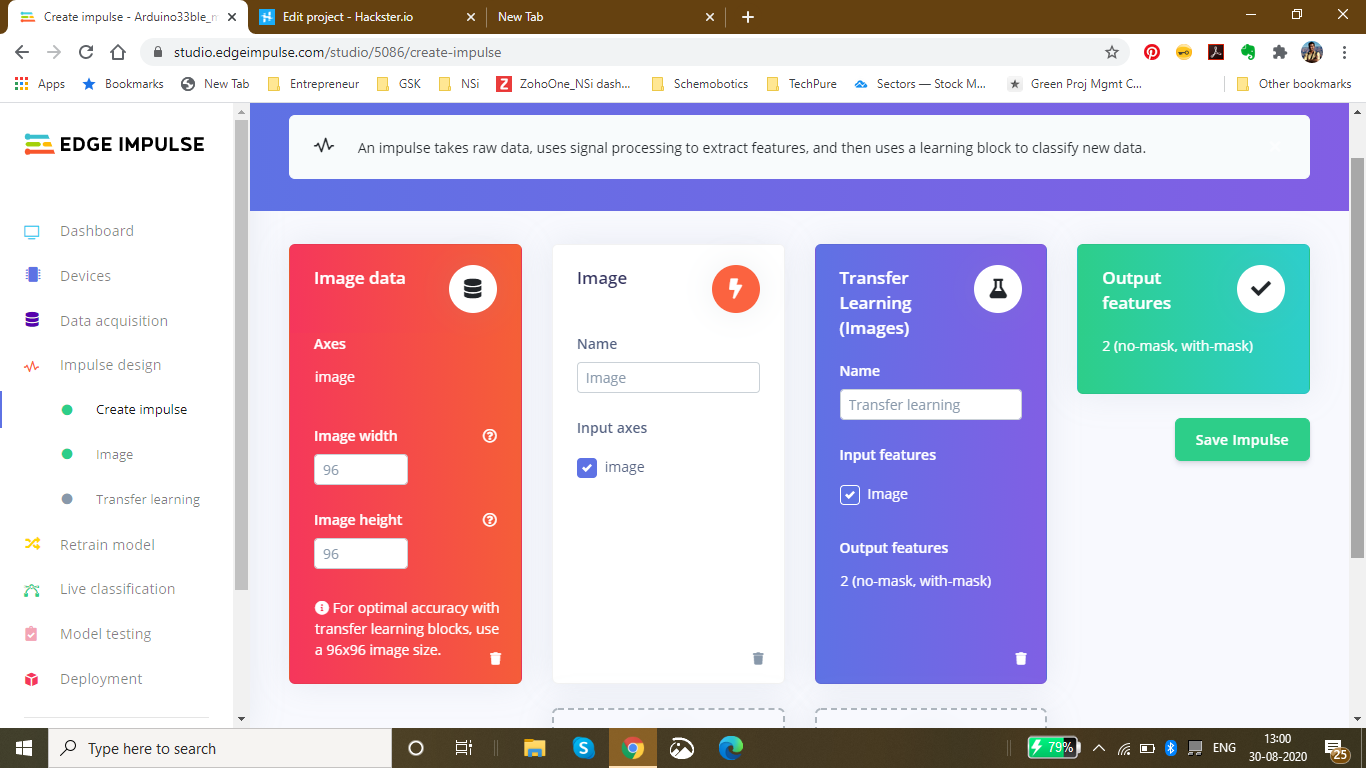
Then, I went ahead creating an impulse design which best suited the Model type. For optimal accuracy its recommended to use a standard image size which is 96*96 and also works the best on the Arduino 33 BLE Sense. Since the input type was images, I went ahead and selected "images" in the processing block. For the transfer learning block, the type recommended for image learning is Transfer Learning (Images) which is a Fine tune a pre-trained image model on your data. with Good performance even with relatively small image datasets.
The next step was saving the parameters based on color depth. Here, I have selected RGB because in the dataset I am using for mask detection, color is also an important feature of classification instead of grayscale. In this page, we can also see the raw features with the processed features of the image
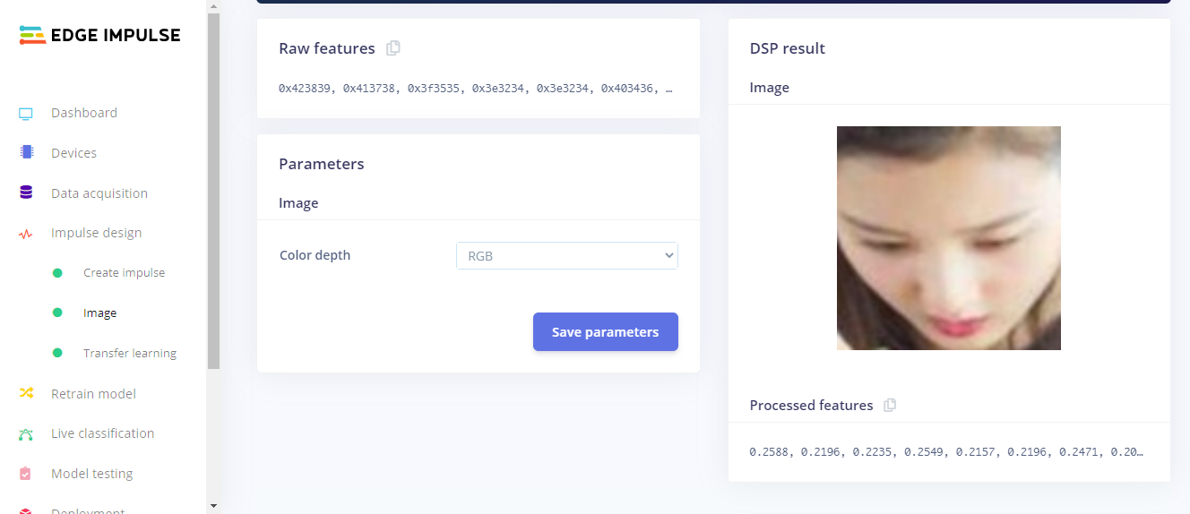
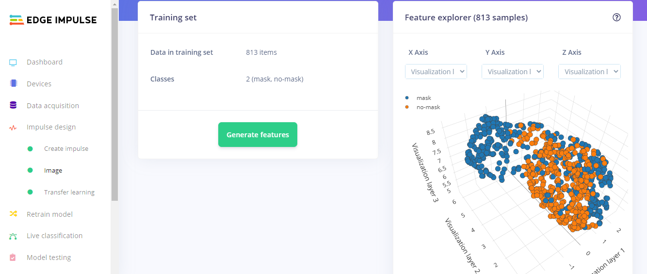
After Feature Generation I obtained the classification graph or the feature explorer where I could see the classes based on their classifications. The blue dots represent mask images and the orange dots represent the no_mask images.
In this feature generation, I obtained a fair classification with a distinct classification plot.
Finally, Moving on to the Transfer Learning Plot:
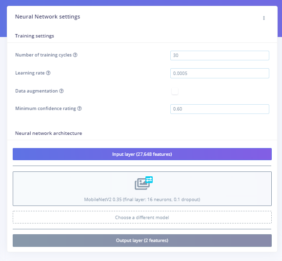
Here, I set the number of training cycles/epochs as 30 to get the highest accuracy with minimum val_loss. It so happens that if we train the model based on many training cycles, the accuracy graph starts to decrement after a certain number of epochs and the val_loss increases. Therefore I decided to limit the epochs to 30 which proved to be perfect. The learning rate is set to 0.0005 which is the default and proves to be the most appropriate. Here, I have used the MobileNetV2 0.35 (final layer:16 neurons, 0.1 dropout) model because this model is comparitively lightweight and accurate.
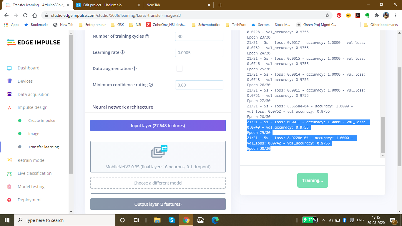
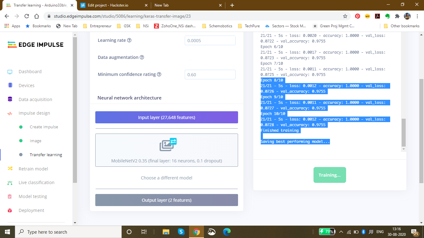
Finally after completing 30 epochs and 10 epochs of best model performance, I got the accuracy heading to 1.00 and the loss nearly 0 which was 0.0011. The following was the ouput during the training process:
Saving best performing model... Converting TensorFlow Lite float32 model... Converting TensorFlow Lite int8 quantized model with float32 input and output...
- Epoch 9/10 21/21 - 5s - loss:0.0011 - accuracy:1.0000 - val_loss:0.0727 - val_accuracy:0.9755
- Epoch 10/10 21/21 - 5s - loss:0.0012 - accuracy:1.0000 - val_loss:0.0728 - val_accuracy:0.9755 Finished training
This was the final output which I received after the training:
The accuracy to be 92.6% and the loss to be 0.19.
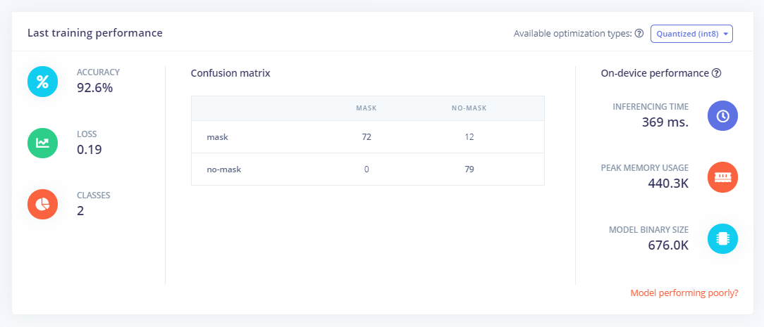
Finally Using the test data, I tested the accuracy and found it to be 98.15%.
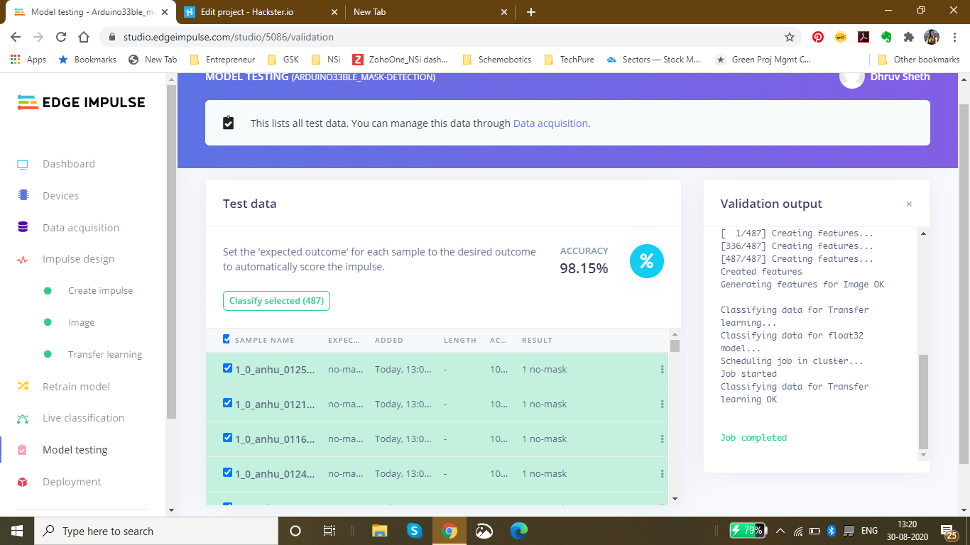
Finally since I had the model ready, I deployed it as an Arduino Library with the firmware to be the Arduino 33 BLE Sense:I got the zip folder of the library ready and started to make changes as per our requirements.
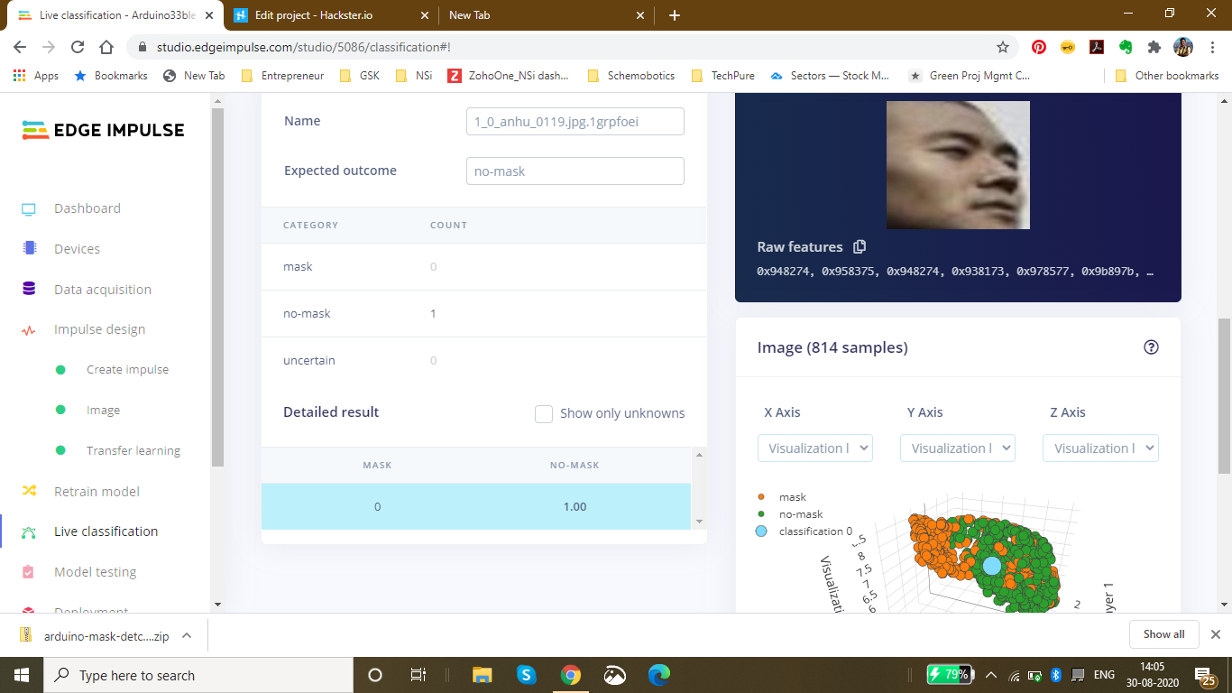
For a last confirmation, I live classified the data to ensure that the data is classified properly. I got the perfect results as expected:
Changing the code as per the output required in the model:
Here is a snippet of the main.ino code of the mask_detection model
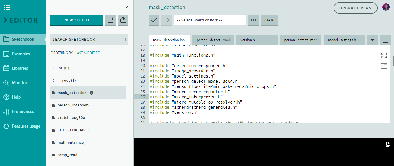
I have defined the arduino libraries required for the functioning of the model and based on the Tensorflow lite framework, I have designed this model.
This is the loop of some of the main functions in the model which are defined in the libraries. The main.ino code centralises these functions and accordingly loops them with a central code.
void loop() {
 // Get image from provider.
 if (kTfLiteOk !=GetImage(error_reporter, kNumCols, kNumRows, kNumChannels,
 input->data.uint8)) {
 TF_LITE_REPORT_ERROR(error_reporter, "Image capture failed.");
 }

 // Run the model on this input and make sure it succeeds.
 if (kTfLiteOk !=interpreter->Invoke()) {
 TF_LITE_REPORT_ERROR(error_reporter, "Invoke failed.");
 }

 TfLiteTensor* output =interpreter->output(0);

 // Process the inference results.
 uint8_t mask_score =output->data.uint8[kmaskIndex];
 uint8_t no_mask_score =output->data.uint8[kno-maskIndex];
 RespondToDetection(error_reporter, mask_score, no_mask_score);
}
The processed data of this model can be viewed here :(This file is relatively large and varies as per the dataset size of the model) Arduino_mask_detect_model_data.h
For providing image, I will be using the Arducam mini 2mp plus for visual data input. A snippet from the image_provider.h file is :
#include "image_provider.h"

/*
 * The sample requires the following third-party libraries to be installed and
 * configured:
 *
 * Arducam
 * -------
 * 1. Download https://github.com/ArduCAM/Arduino and copy its `ArduCAM`
 * subdirectory into `Arduino/libraries`. Commit #e216049 has been tested
 * with this code.
 * 2. Edit `Arduino/libraries/ArduCAM/memorysaver.h` and ensure that
 * "#define OV2640_MINI_2MP_PLUS" is not commented out. Ensure all other
 * defines in the same section are commented out.
 *
 * JPEGDecoder
 * -----------
 * 1. Install "JPEGDecoder" 1.8.0 from the Arduino library manager.
 * 2. Edit "Arduino/Libraries/JPEGDecoder/src/User_Config.h" and comment out
 * "#define LOAD_SD_LIBRARY" and "#define LOAD_SDFAT_LIBRARY".
 */

#if defined(ARDUINO) &&!defined(ARDUINO_ARDUINO_NANO33BLE)
#define ARDUINO_EXCLUDE_CODE
#endif // defined(ARDUINO) &&!defined(ARDUINO_ARDUINO_NANO33BLE)

#ifndef ARDUINO_EXCLUDE_CODE

// Required by Arducam library
#include
#include
#include
// Arducam library
#include
// JPEGDecoder library
#include

// Checks that the Arducam library has been correctly configured
#if !(defined OV2640_MINI_2MP_PLUS)
#error Please select the hardware platform and camera module in the Arduino/libraries/ArduCAM/memorysaver.h
#endif
The Arduino_detection_responder.cpp code performs the inference and delivers the main output required for the code. Here, when a person with a mask is detected, we are opening the gate and if a person with no mask is detected, we are closing the gate.
// Switch on the green LED when a mask is detected,
 // the red when no mask is detected
 if (mask_score> no_mask_score) {
 digitalWrite(LEDG, LOW);
 digitalWrite(LEDR, HIGH);
 servo_8.write(0); // this servo moves to 0degrees in order to open the mall door when a person is detected to ensure no touch entry system
 count++
 } else {
 digitalWrite(LEDG, HIGH);
 digitalWrite(LEDR, LOW);
 servo_8.write(180); // this servo moves to 180degrees when no person is detected
 count2++
 }
The count and count2 are variable integers and increment everytime a mask is detected, or not detected. These counts are then displayed onto the ThingSpeak IoT Dashboard as follows:
The graph displays the mask and no mask count over time. This thingspeak dashboard is setup in the Arduino code as seen here:
#include
#include
WiFiMulti WiFiMulti;
const char* ssid ="Yourssid"; // Your SSID (Name of your WiFi)
const char* password ="Wifipass"; //Your Wifi password
const char* host ="api.thingspeak.com/channels/1118220";
String api_key ="9BRPKINQJJT2WMWP"; // Your API Key provied by thingspeak
The complete code for responder can be viewed here:Arduino_detection_responder.cpp
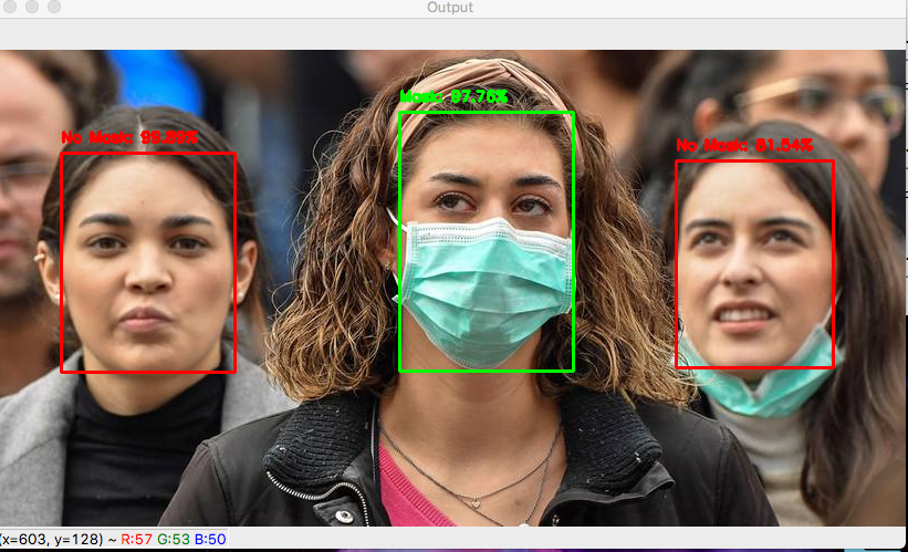
Github Code can be viewed here:Arduino Mask Detetction
The ThingSpeak dashboard can be viewed here - IoT Dashboard
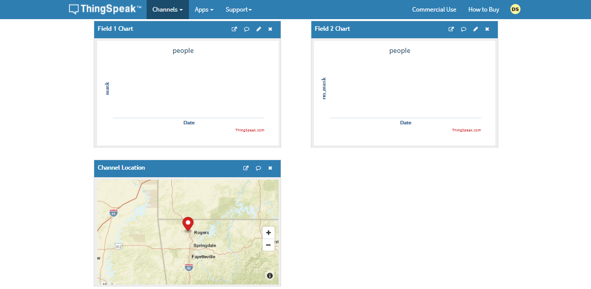
5th project - Person detection in supermarket Aisles and self-sanitisation system:
Just as malls and supermarkets and retail sectors have opened, a risk of contamination of the virus has increased. The main risk that is faced is in supermarkets and stores. The stores could be related to clothes, food and even electronics, the virus could deposit and stay on these surfaces for a long time.
Early data suggests the new coronavirus can live on surfaces for several days
The new coronavirus is, well, new — and there's still much to learn about how easily the virus can spread via contaminated surfaces. But early evidence indicates that the surface survivability of the new coronavirus is similar to that of SARS, a related coronavirus first identified in 2002. Depending on the surface, the virus can live on surfaces for a few hours or up to several days.
The new coronavirus seems to be able to survive the longest on plastic and stainless steel — potentially as long as three days on these surfaces. It can also live on cardboard for up to 24 hours.
Find out what this means for the things you touch throughout the day, including your:
- Clothes
- Food
- Groceries
- Packages
- Électronique
The coronavirus pandemic has breathed new life into a decades-old technique that can zap viruses and bacteria:ultraviolet light.
Hospitals have been using it for years to cut down on the spread of drug-resistant superbugs and to disinfect surgical suites. But there is now interest in using the technology in spaces like schools, office buildings, and restaurants to help reduce coronavirus transmission once public spaces are open again.
The sanitizing effects of UV lights have been seen with other coronaviruses, including the one that causes severe acute respiratory syndrome (SARS). Studies have shown that it can be used against other coronaviruses. One study found at least 15 minutes of UVC exposure inactivated SARS, making it impossible for the virus to replicate. New York's Metropolitan Transit Authority announced the use of UV light on subway cars, buses, technology centers, and offices. The National Academy of Sciences says although there is no concrete evidence for UV’s effectiveness on the virus that causes COVID-19, it has worked on other similar viruses, so it would likely fight this one too.
Abiding by the given information, Malls and Supermarkets have started imposing solutions based on UV sanitisation on manual basis. This consumes a lot of time and also, the data is unavailable. In manual process, one does not know which area has been exposed to human touch more or which are has the highest risk of contamination.
To automate this process and to provide real time spatial analysis of the data collected and the rate of contamination in an area.

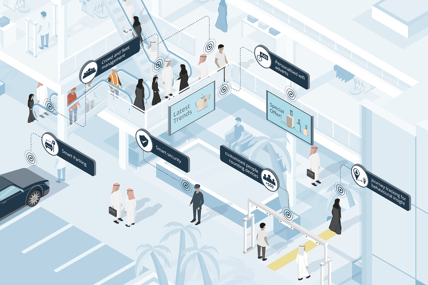
The above images demonstrate the distribution of population across the mall. As it is clearly seen in Figure B, the density near the escalator is comparatively high as compared to the density on the second floor. Manually keeping a track of this continuously changing data in real time and accordingly, sanitising the areas/aisles according to the rate of contamination is not a manual task.
Hence, I decided to make a robust solution for automating this process with the help of TinyML computer Vision &IoT deployed on the Arduino 33 BLE Sense.
The structured framework of this system is as follows:
These models are individually deployed on the Aisles and Areas of the malls and supermarkets close to the Area which has to be sanitised. Since the model utilises person detection Algorithm, the placement of the model is done accordingly.
In this model, for accumulation of Video data, the Arducam mini 2MP Plus is used. The Arducam Mini 2MP Plus continuously gathers visual data and sends this data to the Arduino Nano 33 BLE Sense for processing and classification. The Arduino classifies the data and accordingly processes commands. If a person is detected, the count of people increments by 1 on detection of each person near the Aisle.
A certain threshold for the count of people is set depending upon the rate of contamination based on the object type in that area. The rate of contamination and threshold for food aisle, clothes aisle, sports aisle and Electronic aisle is different.
Accordingly taking into consideration an average threshold, if 25 people are detected, the area is safe. If the count increases to 50, the area is heading towards contamination and the visitors are given an alert. If the count increases to 100, the area is declared contaminated and the people are warned to be careful while touching objects. Finally if the threshold limit is crosses which is 150, the area is autonomously sanitised using UV Light.
The alerts generated are based on LED Colours. Green is an indication for safe, blue is an indication for alert, and Red is an indication for Warning!. These LED based alerts are installed in the respective areas individually.
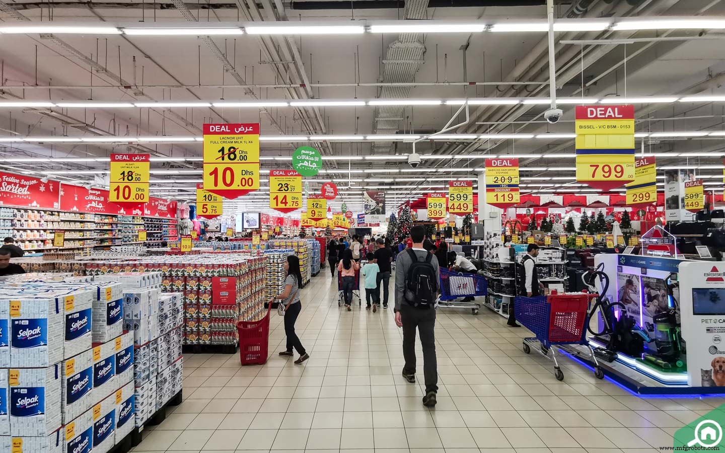
The above image shows the various aisles in the malls where the system can be installed.
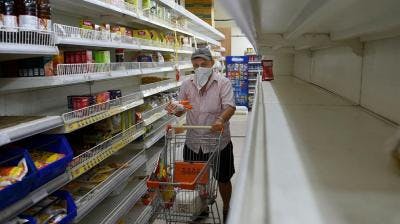
The above image shows the area of installation of Arducam or similar visual data capturing device to cover a wide spectrum of people walking through the aisle.
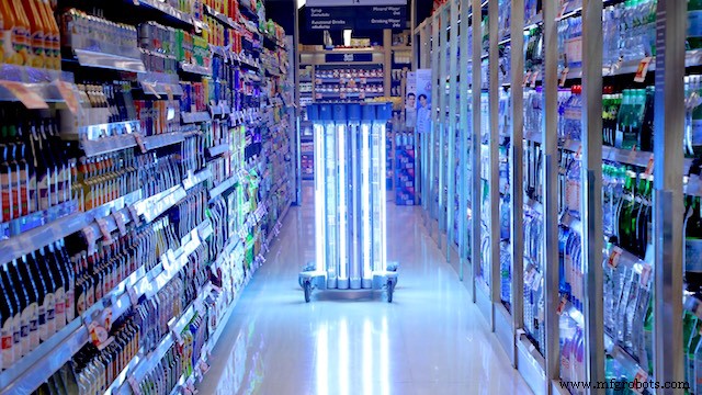

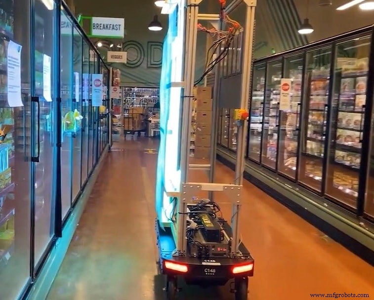
The above Images show a demo implementation of the UV Sanitisation Lights in suitable areas of the aisles. This UV light covers a large spectrum of area that can be sanitised together.
Implementation of the autonomous sanitisation system.
The following Softwares have been used in designing this model:
- TensorFlow lite
- ThingSpeak
- Arduino Web Editor
In this person detection model, I have used the Pre-trained TensorFlow Person detection model apt for the project. This pre-trained model consists of three classes out of which the third class is with undefined set of data:
"unused",
"person",
"notperson"
In our model we have the Arducam Mini 2mp plus to carry out image intake and this image data with a decent rate of fps is sent to the Arduino Nano 33 BLE Sense for processing and and classification. Since the Microcontroller is capable of providing 256kb RAM, we change the image size of each image to a standard 96*96 for processing and classification. The Arduino Tensorflow Lite network consists of a deep learning framework as:
- Depthwise Conv_2D
- Conv_2D
- AVERAGE Pool_2D
- Flatten layer
This deep learning framework is used to train the Person detection model.
The following is the most important function defined while processing outputs on the Microcontroller via Arduino_detetction_responder.cpp
// Process the inference results.
 uint8_t person_score =output->data.uint8[kPersonIndex];
 uint8_t no_person_score =output->data.uint8[kNotAPersonIndex];
 RespondToDetection(error_reporter, person_score, no_person_score);
In the following function defining, the person_score , the no_person_score have been defined on the rate of classification of the data.
using these defined functions, I will be using it to give certain outputs on the basis of confidence of the person_score and the no_person_score .
The detection responder logic of the code works in the following way:
├── Person Detection and sanitisation
├── Arducam mini 2MP Plus
│ ├──Image and Video Data to Arduino
├── Arduino BLE 33 Sense
│ ├── processing and classification of the input data
│ │ ├── If person detected, increment the count by 1
│ │ ├── If no person detected, do nothing
│ │ ├── Send the number of people entered count to to ThingSpeak Dashboard via ESP8266 -01
│ │ | ├── If people count is uptil 25
│ │ │ | ├── Indicate the area to be safe by flashing green light
│ │ | ├── If people count is uptil 50
│ │ │ | ├── Indicate the people to be aware by flashing blue light
│ │ | ├── If people count is uptil 100
│ │ │ | ├── Indicate the area to be contaminated by flashing Red light
│ │ | ├── If people count is between 150 to 175
│ │ │ | ├── Sanitise the area by activating the UV light
│ │ │ | ├── Reset the person count to 0 since the area has been sanitised
│ │ └── ...Repeat the loop
According to the logic used in the model, the Arducam Mini 2MP Plus will continuously capture visual data and send this data to the Arduino Nano 33 BLE sense to process and classify. This model size is 125Kb. Once the image is processed, the Arduino starts to classify the data captured. If a person is detected in the model, the person count increases by 1. This person count is continuously sent to the ThingSpeak dashboard via ESP8266- 01 IoT module. The person count enables the supermarket staff with the data of number of visitors in a particular area at any given point of time. The staff can generate data driven decisions to take action in an area if the visitor count is significantly high.
Proceeding to the output, if the person count is between 1 to 25, the Area is declared safe by flashing the green LED. If the person count is between 26 to 50, the visitors are given an alert by flashing BLUE LED. If the count is between 51 to 100, the area is declared contaminated by flashing the RED LED. When the count surpasses a certain threshold, here taken to be 150, the UV light is turned on until the 165th person passes the area. In this way the Area is sanitised. Similarly the count of people is reset to 0 since the area has been sanitised.
Working of the Firmware:

This model comprises of the following firmware used:
- Arduino 33 BLE sense - Used to process the data gathered, classifies the data processes, sends the command according to the logic fed.
- Arducam Mini 2mp plus - Continuous Raw data image accumulation from source.
- Adafruit lithium ion charger - Used to deliver charge through the lithium battery
- Lithium ion Battery - power source
- ESP8266 - 01 - Used for sending data to the ThingSpeak dashboard via WiFi network.
- RGB LED - Used for flashing Signals based on the status of contamination
- UV Light - Used to Sanitise the Area ( Since this is a prototype, an LED is displayed. In the actual solution, the UV light consumes a lot of energy hence an external power source needs to be provided. )
Functioning and Working of Logic in Code:
The following are the Libraries included in themain.ino c ode for functioning of the model.
#include

#include "main_functions.h"

#include "detection_responder.h"
#include "image_provider.h"
#include "model_settings.h"
#include "person_detect_model_data.h"
#include "tensorflow/lite/micro/kernels/micro_ops.h"
#include "tensorflow/lite/micro/micro_error_reporter.h"
#include "tensorflow/lite/micro/micro_interpreter.h"
#include "tensorflow/lite/micro/micro_mutable_op_resolver.h"
#include "tensorflow/lite/schema/schema_generated.h"
#include "tensorflow/lite/version.h"
The main outcome of the model is dependent on the logic fed in detection_responder.cpp. This snippet shows the generalized threshold of the contamination of the object set to a count of 101.
void RespondToDetection(tflite::ErrorReporter* error_reporter,
 uint8_t person_score, uint8_t no_person_score) {
 static bool is_initialized =false;
 if (!is_initialized) {
 // Pins for the built-in RGB LEDs on the Arduino Nano 33 BLE Sense
 pinMode(LEDR, OUTPUT);
 pinMode(LEDG, OUTPUT);
 pinMode(LEDB, OUTPUT);
 is_initialized =true;
 }

 // Note:The RGB LEDs on the Arduino Nano 33 BLE
 // Sense are on when the pin is LOW, off when HIGH.

 // Switch the person/not person LEDs off
 digitalWrite(LEDG, HIGH);
 digitalWrite(LEDR, HIGH);

 // Flash the blue LED after every inference.
 digitalWrite(LEDB, LOW);
 delay(100);
 digitalWrite(LEDB, HIGH);

 // Switch on the green LED when a person is detected,
 // the red when no person is detected
 if (person_score> no_person_score) {
 digitalWrite(LEDG, LOW);
 digitalWrite(LEDR, HIGH);
 count++
 } else {
 digitalWrite(LEDG, HIGH);
 digitalWrite(LEDR, LOW);
 }

 TF_LITE_REPORT_ERROR(error_reporter, "Person score:%d No person score:%d",
 person_score, no_person_score);
}


 if (constrain(count, 1, 50)) {
 digitalWrite(LEDGREEN, LOW); // This is a green LED which means area is not contaminated yet
}
 if (constrain(count, 51, 75)) {
 digitalWrite(LEDBLUE, LOW); // This is a b led so that people are alert that more than 50 people
}
 if (constrain(count, 76,100)) {
 digitalWrite(LEDRED, LOW); // This is a red LED which warns people that this area is contaminated and one should take care while touching objects
}
 if (constrain(count, 101, 110)) {
 digitalWrite(UV, LOW); // This is an Ultraviolet Light which ensures that after 100 people have touched the aisle objects, it sanitises the area with UV light
 }
 if (count> 111) {
 (count =0); // this resets the person count to 0 once the area has been sanitised by UV light
 }
 } // In this way, a simple math function has been written by me on the arduino nano 33 ble sense which alerts people and sanitizes areas
/* cc - Dhruv Sheth */
The below snippet is carried out by the ESP8266 -01 module to send data to the allocated field in the ThingSpeak Dashboard:
void Send_Data()
{


 // Use WiFiClient class to create TCP connections
 WiFiClient client;

 const int httpPort =80;

 if (!client.connect(host, httpPort)) {
 Serial.println("connection failed");
 return;
 }
 else
 {
 String data_to_send =api_key;
 data_to_send +="&field1=";
 data_to_send +=String(count);
 data_to_send +="\r\n\";

 client.print("POST /update HTTP/1.1\n");
 client.print("Host:api.thingspeak.com\n");
 client.print("Connection:close\n");
 client.print("X-THINGSPEAKAPIKEY:" + api_key + "\n");
 client.print("Content-Type:application/x-www-form-urlencoded\n");
 client.print("Content-Length:");
 client.print(data_to_send.length());
 client.print("\n\n");
 client.print(data_to_send);

 delay(10); // reduced delay to perform real time data collection
 }

 client.stop();

} 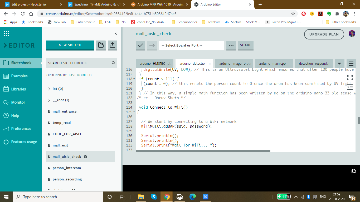
The threshold for each Aisle inside the mall is set to be different according to the rate of contamination of the model. This data can be altered according to the need of the malls or supermarkets. These thresholds can also be altered according to the time trends and the population density in that area.
Threshold set for the Clothes Aisle:
if (constrain(count, 1, 50)) {
 digitalWrite(LEDGREEN, LOW); // This is a green LED which means area is not contaminated yet
}
 if (constrain(count, 51, 75)) {
 digitalWrite(LEDBLUE, LOW); // This is a b led so that people are alert that more than 50 people
}
 if (constrain(count, 76,100)) {
 digitalWrite(LEDRED, LOW); // This is a red LED which warns people that this area is contaminated and one should take care while touching objects
}
 if (constrain(count, 101, 110)) {
 digitalWrite(UV, LOW); // This is an Ultraviolet Light which ensures that after 100 people have touched the aisle objects, it sanitises the area with UV light
 }
 if (count> 111) {
 (count =0); // this resets the person count to 0 once the area has been sanitised by UV light
 }
Threshold for the Electronics Aisle, since the virus stays on these surfaces comparatively less, we have set a higher threshold in this case.
if (constrain(count, 1, 75)) {
 digitalWrite(LEDGREEN, LOW); // This is a green LED which means area is not contaminated yet
}
 if (constrain(count, 76, 180)) {
 digitalWrite(LEDBLUE, LOW); // This is a b led so that people are alert that more than 50 people
}
 if (constrain(count, 181,225)) {
 digitalWrite(LEDRED, LOW); // This is a red LED which warns people that this area is contaminated and one should take care while touching objects
}
 if (constrain(count, 225, 240)) {
 digitalWrite(UV, LOW); // This is an Ultraviolet Light which ensures that after 100 people have touched the aisle objects, it sanitises the area with UV light
 }
 if (count> 111) {
 (count =0); // this resets the person count to 0 once the area has been sanitised by UV light
 }
Threshold set for Food and eatables:, Since these are consumptives, they face a higher risk of contamination. Hence, a lower threshold is set in this case.
if (constrain(count, 1, 25)) {
 digitalWrite(LEDGREEN, LOW); // This is a green LED which means area is not contaminated yet
}
 if (constrain(count, 25, 50)) {
 digitalWrite(LEDBLUE, LOW); // This is a b led so that people are alert that more than 50 people
}
 if (constrain(count, 51,75)) {
 digitalWrite(LEDRED, LOW); // This is a red LED which warns people that this area is contaminated and one should take care while touching objects
}
 if (constrain(count, 76, 90)) {
 digitalWrite(UV, LOW); // This is an Ultraviolet Light which ensures that after 100 people have touched the aisle objects, it sanitises the area with UV light
 }
 if (count> 91) {
 (count =0); // this resets the person count to 0 once the area has been sanitised by UV light
 }
Setting up the Thingspeak IoT Dashboard:
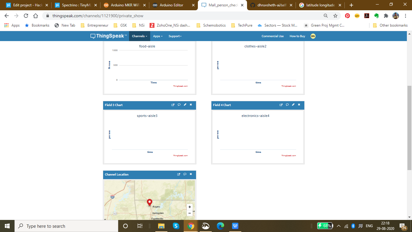
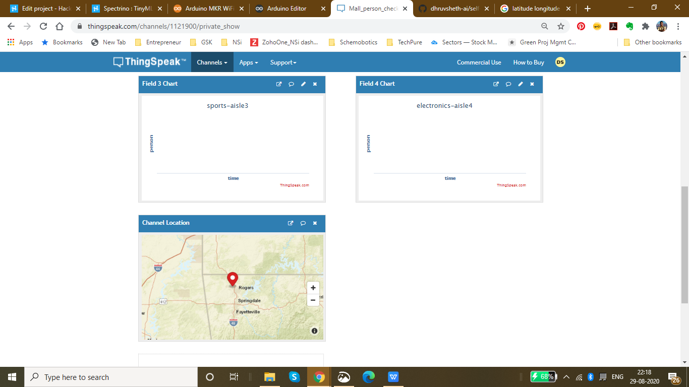
On the thingspeak dashboard, there are 4 fields which have been added for the 4 aisles that have been set up namely:
- Food-aisle
- Sports-aisle
- Clothes-aisle
- Electronics-aisle
The co-ordinate locations of the mall can be seen in the channel visualization which can be cumulatively displayed on a single dashboard through which the data for each supermarket and mall in a locality can be accessed.
The IoT Dashboard can be viewed here:IoT Dashboard
The fields and channels of aisles can be all displayed together on a single Thingspeak IoT Dashboard.
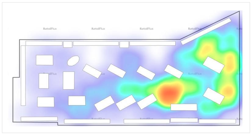
The above image shows a density plot of the density population in a given region in the store of a mall.
Currently I have been using the ThingSpeak Dashboard to plot the data in a graphical format. But, using the same data and Tableau visualizations, it is possible to plot the given data on the floor plot map of the Supermarket.
This data will be easily accessible to other visitors entering the supermarket and will be able to interpret data driven decisions like visiting the store which has a low population density.
Now a question might arise that what makes the product unique:
Currently, the UV sanitisation system is implemented on manual basis and hence the sanitisation system is carried out manually monitoring these areas. Autonomous UV robots are deployed in malls to gather plot data of mall and map these areas, hence autonomously sanitising these areas. These solutions are not capable of sanitising each aisle and area in the mall along with the flowing population of the people in the mall. The sanitisation is only limited to sanitising the lower part of these aisles and hence the upper parts are left unsanitised. These solutions are also comparatively expensive and they are not capable of continuous data monitoring and sanitisation respective to the rate of contamination. This means that they are unable to monitor the number of people who have passes through a certain area or aisle and hence are unable to sanitise areas according to their contamination.
Go to Market and Viability:
- Malls and Supermarkets can use this to identify The count of people in and density of people in a certain area in a store and impose self sanitisation process within the malls.
- Implement Strategies using this data to ensure Safety and Compliance with efficient Population Density monitoring algorithms.
- Decrease Labour and automate Sanitisation process.
- Offer Dashboard to the visitors to monitor the density of people at a certain area inside the mall and accordingly the visitors can have a view of the store with lowest density population and make decisions based on this data. The visitors can also have a view of the timely trends of sanitisation by viewing the abrupt change of person density graph in an area when sanitisation is conducted. ( Since, each time sanitisation in an area takes place, the person count is reset to 0 because the place is sanitised)
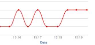
- This product can be used to ensure the visitors that the mall is a safe place and hence, can increase the sales and visits following Government guidelines
- Companies offering Ai and IoT based solutions can invest for mass production and distribution.
- The more the supermarkets using this product, the more the access to data to the government and more the choice to customers to select the preferable safest place in their locality and which store is continuously sanitised to be up to mark in terms of safety. This will lead to a wide range of options of supermarkets in the locality comparing the queue time and safety.
- Comparatively affordable solution as compared to autonomous UV Robot system and highly scalable in terms of data and services with IoT Dashboard provided.
- Utilize real-time CCTV footage to impose autonomous sanitisation system through person detection in terms of timely trends and spatial analysis of person density in the mall.
- Enable Stores to make better, data-driven decisions that ensure your safety and efficient Queues based on autonomous queuing system.
Github Link :https://github.com/dhruvsheth-ai/self-sanitisation-person-detection
PROJECT VIDEO:
Thank you for viewing my project!
Code
- Elevator Automation using "up" - "down" speech command
Elevator Automation using "up" - "down" speech commandArduino
The below is a .zip file of the Arduino LibraryNo preview (download only).
Mall Aisle Self Sanitization with Person Detection System
https://github.com/dhruvsheth-ai/self-sanitisation-person-detetctionTemperature monitoring system based on IoT
https://github.com/dhruvsheth-ai/temperature-arduino-iotMask Detection Algorithm
https://github.com/dhruvsheth-ai/ble-mask-detection-optimisedAutonomous Person Intercom based on TinyML
https://github.com/dhruvsheth-ai/person-autonomous-intercomElevator Automation using TinyML
https://github.com/dhruvsheth-ai/elevator-Automation-ARDUINOMall Entrance Person Detection and Queuing System
Queuing System based on TinyML person detection on Mall Entrance and exit connected via IoT Thingspeak dashboard for Live data monitoringhttps://github.com/dhruvsheth-ai/Person-queuing-system-arduino33Schémas
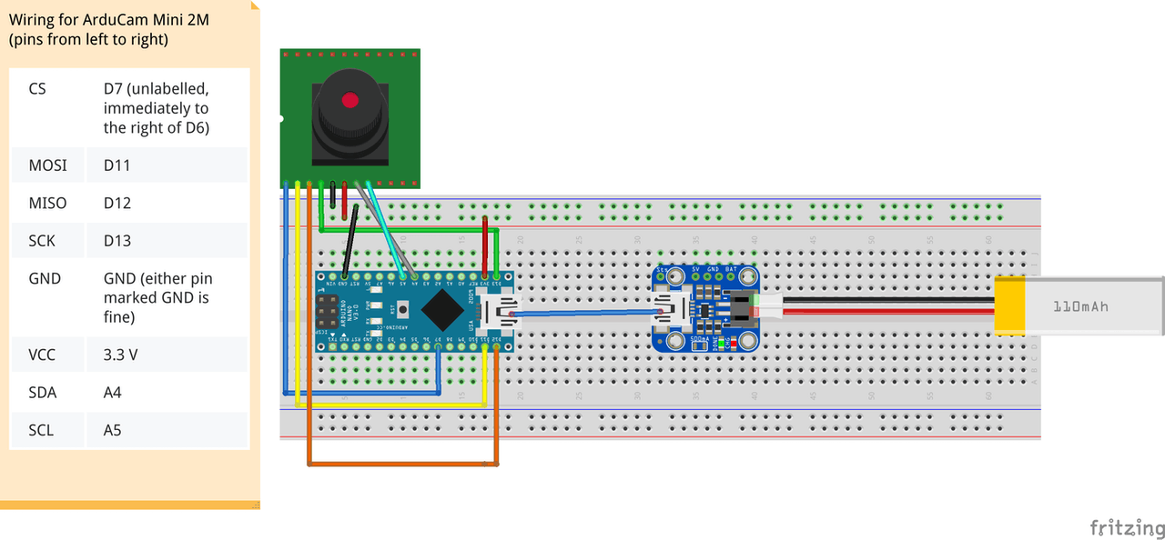
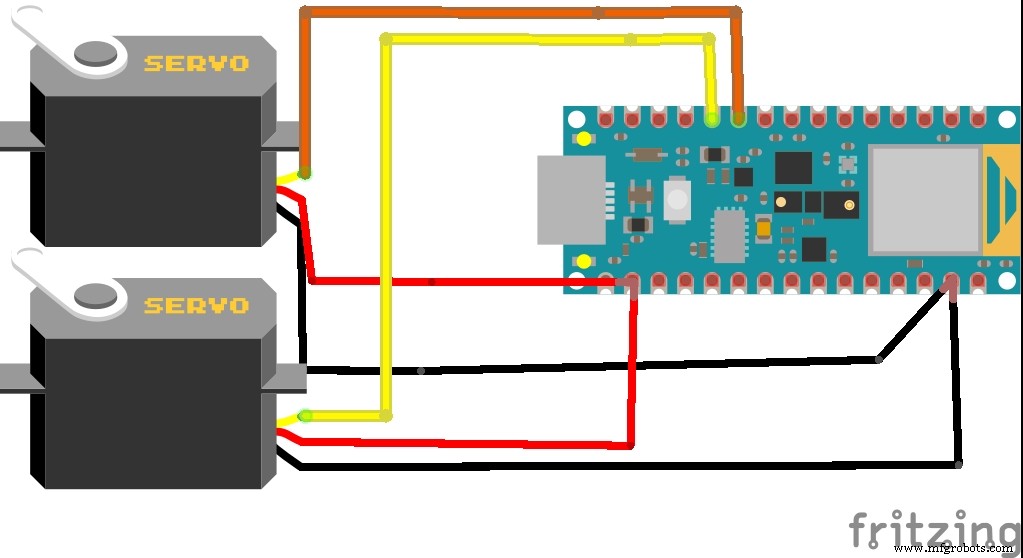
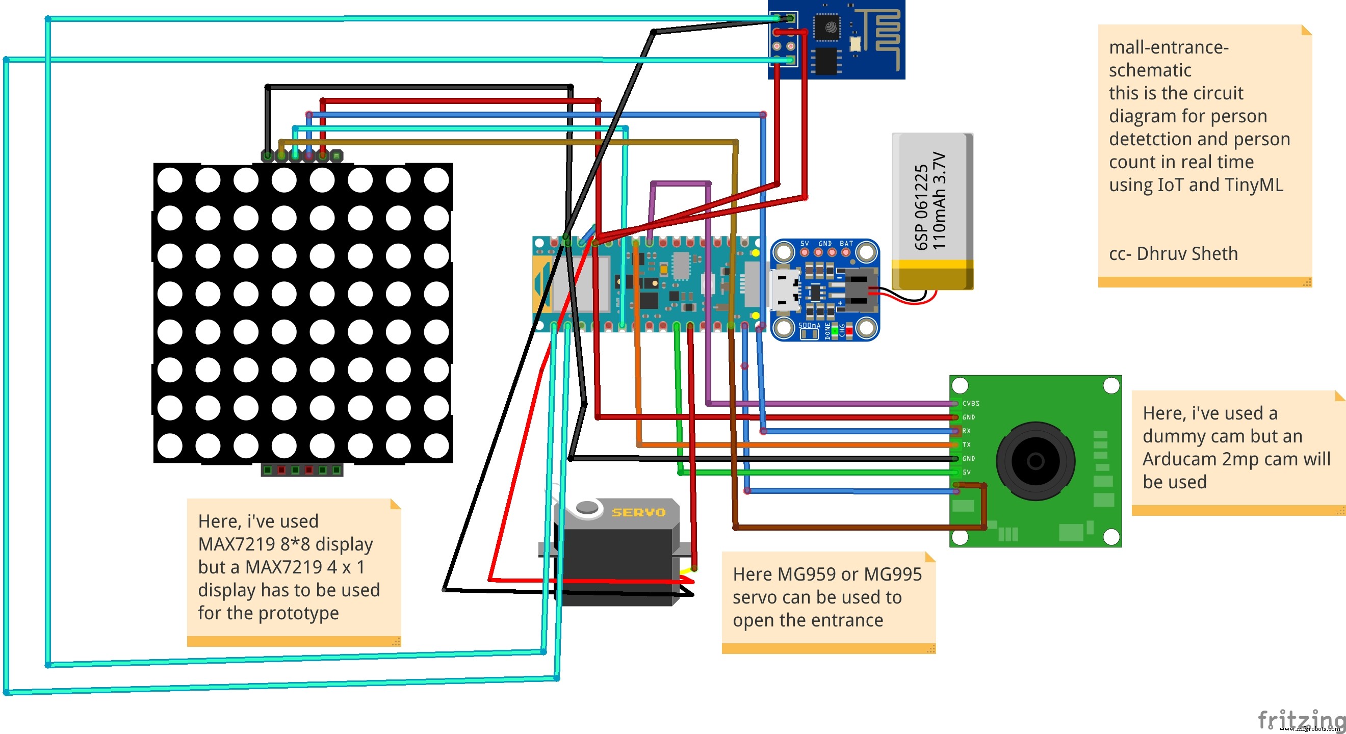 This is the Schematic for the Mall Aisle Person detection and self sanitization system that transfers data to ThingSpeak IoT Dashboard
 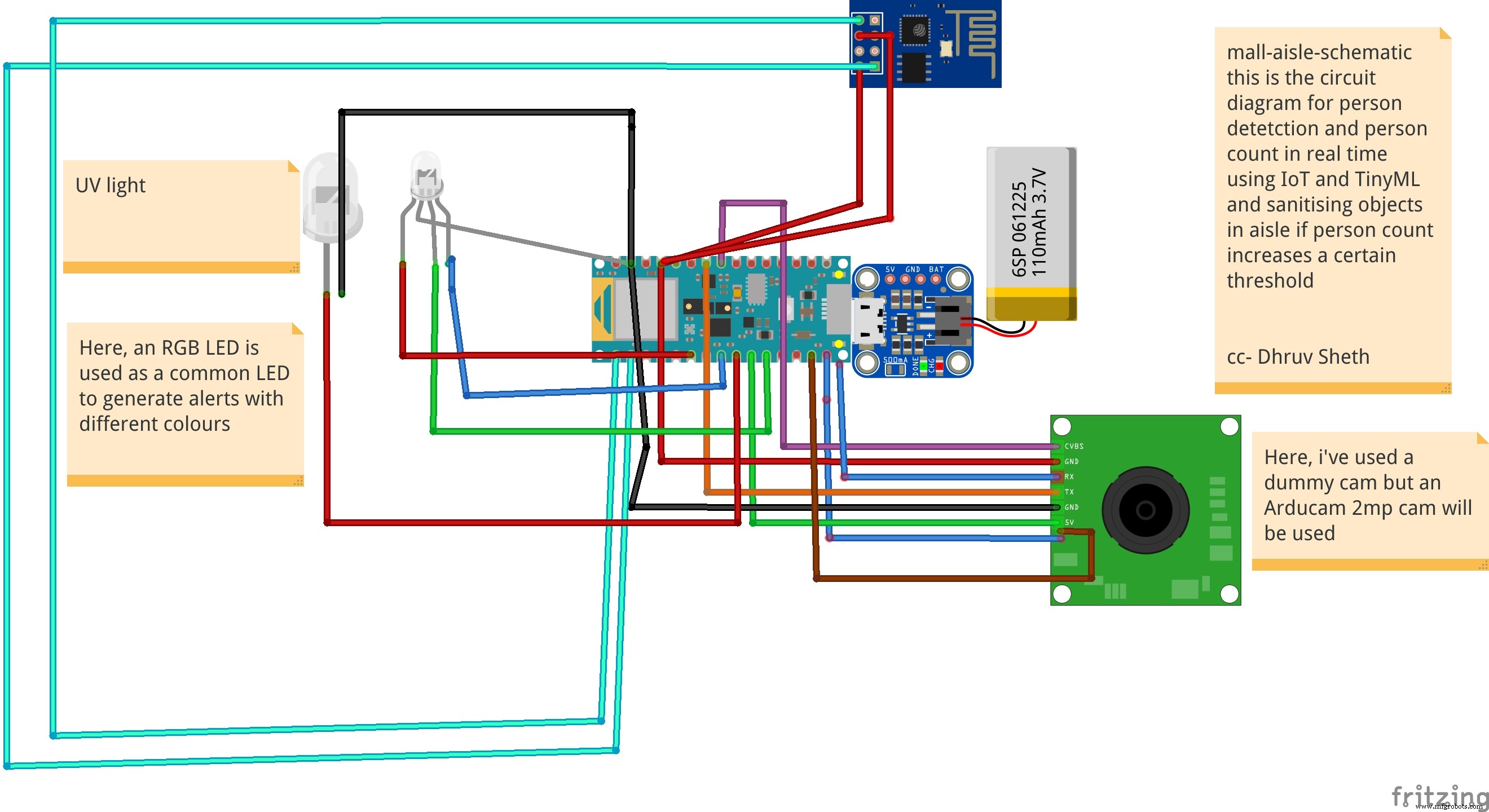 Detects a person present at the door and rings the bell and displays "person" on the LED Matrix as an alternative
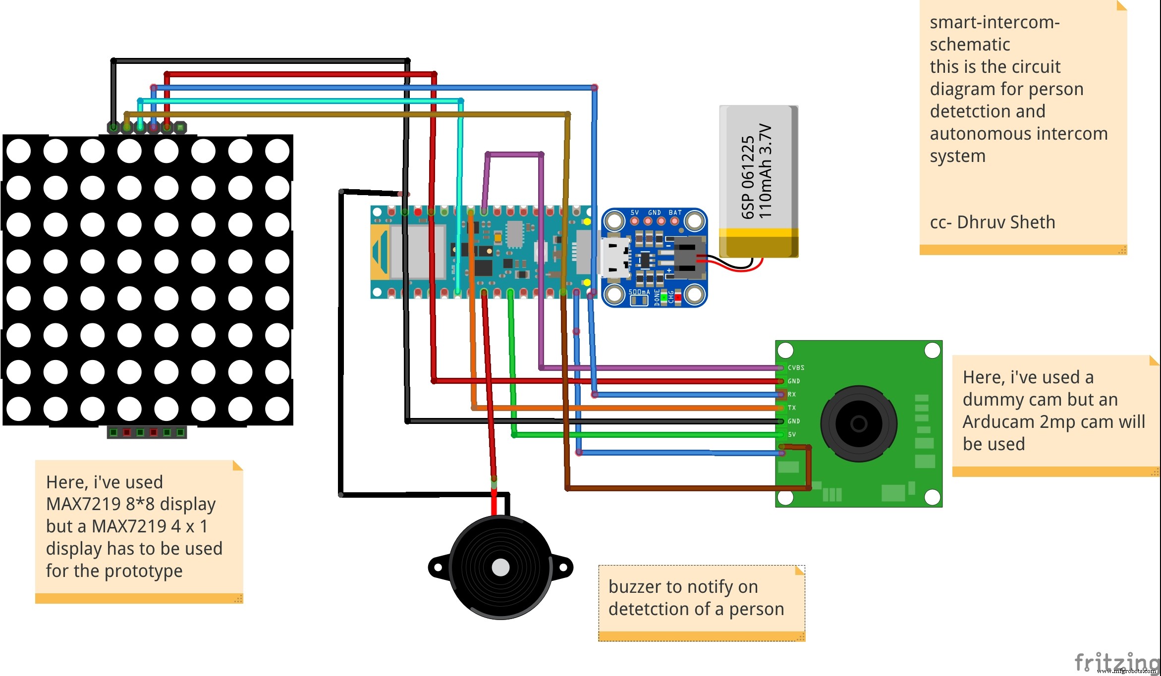
Processus de fabrication
- Raspberry PI Based IoT Project Connecting DHT11 Sensor
- Protocoles sans fil pour les solutions de suivi des actifs basées sur l'IoT
- Jeu Arduino Pong - Écran OLED
- Moniteur de fréquence cardiaque utilisant l'IoT
- Pixie :une montre-bracelet NeoPixel basée sur Arduino
- Jouer avec Nextion Display
- Automates cellulaires basés sur Arduino et OLED
- Piscine Azure IoT
- Solutions basées sur l'IoT pour les camions à wagon ouvert